EP1348493A2 - Réglage motorisé d'un tamis - Google Patents
Réglage motorisé d'un tamis Download PDFInfo
- Publication number
- EP1348493A2 EP1348493A2 EP03007008A EP03007008A EP1348493A2 EP 1348493 A2 EP1348493 A2 EP 1348493A2 EP 03007008 A EP03007008 A EP 03007008A EP 03007008 A EP03007008 A EP 03007008A EP 1348493 A2 EP1348493 A2 EP 1348493A2
- Authority
- EP
- European Patent Office
- Prior art keywords
- sieve
- screen
- elements
- screening device
- adjusting
- Prior art date
- Legal status (The legal status is an assumption and is not a legal conclusion. Google has not performed a legal analysis and makes no representation as to the accuracy of the status listed.)
- Granted
Links
Images







Classifications
-
- B—PERFORMING OPERATIONS; TRANSPORTING
- B07—SEPARATING SOLIDS FROM SOLIDS; SORTING
- B07B—SEPARATING SOLIDS FROM SOLIDS BY SIEVING, SCREENING, SIFTING OR BY USING GAS CURRENTS; SEPARATING BY OTHER DRY METHODS APPLICABLE TO BULK MATERIAL, e.g. LOOSE ARTICLES FIT TO BE HANDLED LIKE BULK MATERIAL
- B07B1/00—Sieving, screening, sifting, or sorting solid materials using networks, gratings, grids, or the like
- B07B1/46—Constructional details of screens in general; Cleaning or heating of screens
- B07B1/4609—Constructional details of screens in general; Cleaning or heating of screens constructional details of screening surfaces or meshes
- B07B1/4636—Regulation of screen apertures
-
- A—HUMAN NECESSITIES
- A01—AGRICULTURE; FORESTRY; ANIMAL HUSBANDRY; HUNTING; TRAPPING; FISHING
- A01F—PROCESSING OF HARVESTED PRODUCE; HAY OR STRAW PRESSES; DEVICES FOR STORING AGRICULTURAL OR HORTICULTURAL PRODUCE
- A01F12/00—Parts or details of threshing apparatus
- A01F12/44—Grain cleaners; Grain separators
- A01F12/446—Sieving means
- A01F12/448—Sieve adjusting means
-
- B—PERFORMING OPERATIONS; TRANSPORTING
- B07—SEPARATING SOLIDS FROM SOLIDS; SORTING
- B07B—SEPARATING SOLIDS FROM SOLIDS BY SIEVING, SCREENING, SIFTING OR BY USING GAS CURRENTS; SEPARATING BY OTHER DRY METHODS APPLICABLE TO BULK MATERIAL, e.g. LOOSE ARTICLES FIT TO BE HANDLED LIKE BULK MATERIAL
- B07B1/00—Sieving, screening, sifting, or sorting solid materials using networks, gratings, grids, or the like
- B07B1/18—Drum screens
-
- B—PERFORMING OPERATIONS; TRANSPORTING
- B07—SEPARATING SOLIDS FROM SOLIDS; SORTING
- B07B—SEPARATING SOLIDS FROM SOLIDS BY SIEVING, SCREENING, SIFTING OR BY USING GAS CURRENTS; SEPARATING BY OTHER DRY METHODS APPLICABLE TO BULK MATERIAL, e.g. LOOSE ARTICLES FIT TO BE HANDLED LIKE BULK MATERIAL
- B07B1/00—Sieving, screening, sifting, or sorting solid materials using networks, gratings, grids, or the like
- B07B1/46—Constructional details of screens in general; Cleaning or heating of screens
- B07B1/4609—Constructional details of screens in general; Cleaning or heating of screens constructional details of screening surfaces or meshes
- B07B1/469—Perforated sheet-like material
-
- B—PERFORMING OPERATIONS; TRANSPORTING
- B07—SEPARATING SOLIDS FROM SOLIDS; SORTING
- B07B—SEPARATING SOLIDS FROM SOLIDS BY SIEVING, SCREENING, SIFTING OR BY USING GAS CURRENTS; SEPARATING BY OTHER DRY METHODS APPLICABLE TO BULK MATERIAL, e.g. LOOSE ARTICLES FIT TO BE HANDLED LIKE BULK MATERIAL
- B07B1/00—Sieving, screening, sifting, or sorting solid materials using networks, gratings, grids, or the like
- B07B1/46—Constructional details of screens in general; Cleaning or heating of screens
- B07B1/50—Cleaning
-
- B—PERFORMING OPERATIONS; TRANSPORTING
- B07—SEPARATING SOLIDS FROM SOLIDS; SORTING
- B07B—SEPARATING SOLIDS FROM SOLIDS BY SIEVING, SCREENING, SIFTING OR BY USING GAS CURRENTS; SEPARATING BY OTHER DRY METHODS APPLICABLE TO BULK MATERIAL, e.g. LOOSE ARTICLES FIT TO BE HANDLED LIKE BULK MATERIAL
- B07B13/00—Grading or sorting solid materials by dry methods, not otherwise provided for; Sorting articles otherwise than by indirectly controlled devices
- B07B13/14—Details or accessories
- B07B13/18—Control
Definitions
- the present application relates to a screening device with at least two screen elements lying on top of each other, each with a plurality of screen holes have, which depend on the relative position of the screen elements to each other form common sieve openings, and an adjusting device.
- a generic screening device is from the published patent application DE 40 27 111 known.
- the screening device described there makes it possible to adjust the relative position of the sieve elements to change the sieve opening.
- the advantage Such a sieve arrangement can be seen in the fact that it is easily scaled down to a large one Spread of different particle sizes is adjustable.
- the advantage of light adaptability to different screenings can only be achieved if there is actually an easy adjustment of the hole size of the screening device is.
- Experiments with a generic screening device have shown that foreign material is between the superimposed surfaces of the screen elements pushes, bulges and thereby an adjustability of the Siebes may be completely blocked, but at least considerably more difficult. The supposed advantage of an easy adjustment of the size of the sieve openings is lost in this way.
- the object of the invention is achieved by at least the sieve elements a clamping element are held together and the relative position of the Sieve elements can be changed relative to one another by actuating motor-driven adjusting means is.
- the combination according to the invention thus enables the size of the sieve opening of the sieve device even during an ongoing sieving process adjust as needed.
- the sieve can also be easily lifted getting cleaned.
- the edges of overlying sieve holes will be moved like scissors on top of each other during the lifting movement, whereby foreign bodies, that could get stuck in the area of the screen holes, captured, cut and sheared off become.
- a screening device 2 which consists of two screen elements lying one on top of the other 4 is formed.
- Each sieve element 4 has a number of sieve holes 6 on.
- Sieve holes 6 of the sieve elements lying one on top of the other 4 together form a sieve opening 8.
- At one end of the sieve device 2 shows an adjusting device 10 which has a lifting cylinder 12.
- a piston rod 14 is arranged in the lifting cylinder 12, which during an adjustment movement the relative position of the upper sieve element 4 in relation to the lower Sieve element 4 changed, the lower sieve element 4 in the embodiment is designed to be fixed.
- an opening is designated as the sieve opening 8 allows the screened material to move completely through the superimposed particle size To move sieve elements 4 through.
- a single screen opening 8 is delimited and separated from other sieve openings 8.
- the lifting cylinder 12 is mounted in a holder 16, which in the exemplary embodiment the fixed lower sieve element 4 is attached.
- the lifting cylinder 12 will actuated by a hydraulic valve 18, which in turn commands it from a Microprocessor M2 receives.
- the microprocessor M2 is connected to a bus system, about the control commands given by a switch 20 by an operator by a microprocessor M1 connected to the switch 20 can be transmitted to the microprocessor M2 to which the hydraulic valve 18 is connected is.
- a bus system a mechanical, hydraulic system can also be used or simple electrical switching connection exist.
- a hydraulic cylinder 12 can also be an electric motor or another suitable servomotor be used.
- the sieve elements 4 are held pressed together by clamping elements 22.
- the clamping elements 22 consist of a screw bolt 24 which passes through the sieve elements 4 is passed and tightened at the end with a screw nut 26 is. To enlarge the contact area and to distribute the contact pressure a washer 28 is placed under the nut 26.
- a screening device 2 can be seen in a side view.
- the adjustment device 10 is attached to an end face of the screening device 2.
- the screening device 2 is suspended on rocker arms 30.
- a swinging motion by the Swinging levers 30 is transmitted, the material to be screened is conveyed via the screening device 2 and enables a screening of the screenings.
- the adjustment device 10 is on the Screening device 2 attached and is indirectly moved by the rocker arms 30.
- a plurality of motorized adjusting means can also be attached to the screening device 2, in particular to enable an adjustment movement in other directions.
- a rotary movement is also one Sieve elements 4 relative to another sieve element 4 possible.
- the adjusting device 10 can be designed such that it is a Stroke movement can be carried out very quickly, for example in pulse form.
- Sizing allows for regular operation of the screening device Intervals or whenever a constipation is registered, one Carry out cleaning stroke in order to make the sieve holes 6 fully continuous again.
- Foreign objects are removed from the edges of the sieve holes, which are rapid Lifting movement can be moved over one another like scissors, cut and sheared off.
- Such a stroke can last, for example, 1-3 seconds. With such a thing short impulse is not to be feared any significant impairment of the sieving result. Rather, there is an increase in performance because the sieve holes all operate without clogging and no machine time for manual cleaning get lost.
- FIG. 3 shows a screening device from a perspective from above.
- Sieve 4 are held together by clamping elements 22.
- the sieve elements 4 each have circular sieve holes 6.
- the sieve elements 4 are in such a relative position to each other, in which there are 6 for each screen hole result in three smaller common sieve openings 8.
- the screening device 2 is in the laterally attached rocker arms 30 held.
- the positioning force of the adjustment device 10 is transmitted via an adjusting lever 32 to an adjusting axis 34 which is firmly connected to a sieve element 4.
- FIG. 4 An enlarged section can be seen in FIG. 4.
- the adjusting device 10 is attached directly to a sieve element 4.
- An additional frame is not shown in the exemplary embodiment.
- the sieve elements 4 are inserted directly into a holding fork 36 which on the Screen elements 4 facing away from an axle stub 38 which in the Rocker arm 30 is mounted.
- the rocker arm 30 is on the outside of a side wall 40 attached.
- the side wall 40 has an opening through which the Axle stub 38 protrudes.
- the holding fork 36 has plug slots 42 in which the sieve elements 4 are held.
- the adjustable sieve element 4 is displaceable stored in a slot 42, while a fixed screen element 4 in Plug slot 42 is set.
- the insertion slots 42 can be designed so that it as a backdrop for guiding a sieve element 4 during an adjustment movement serve.
- FIG. 5 An enlarged view of the frameless screen suspension is shown in Fig. 5.
- the Sieve element 4 has smaller sieve holes 6 in one area and in another Area larger sieve holes 6.
- One is over the screen surface of the screen element 4
- a plurality of clamping elements 22 distributed so that they over the length and width of the sieve element 4 a contact pressure for pressing a further sieve element 4 can generate.
- slots 44 are arranged through which the sieve element 4 is guided during an adjustment process.
- the sieve element 4 has recesses 46 to which an adjusting device 10 are attached can.
- the screen element 4 shown in Fig. 6 is designed so that this only in Area of the larger sieve holes 6 rests on a second sieve element 4.
- the clamping element 22 consists of a screw bolt 24 which is connected to a Screw nut 26 is screwed.
- the contact pressure can be different Tightening torque of the nut 26 can be varied.
- the nut 26 can be set to an initial tightening torque. After multiple adjustments the screening device 2, it may be necessary to tighten the torque Readjust the nut 26. It is also conceivable that the sieves stack on one another have fixed. In this case, it is advantageous to loosen the screw nut 26 in order to be able to easily adjust the sieve elements 4. If the sieve elements 4 are made of stainless steel, at least rusting of the sieve elements 4 to be avoided together.
- the screw bolt 24 is mounted in a pressing body 48, which is from the screw head of the screw bolt 24 is pressed with its underside onto a sieve element 4.
- the contact surface 50 of the pressing body 48 is thus firmly on the surface of the associated Siebiatas 4 pressed. If you try the upper sieve element 4 in one To adjust the direction of the arrow, the frictional forces must first be overcome be that of the bearing surface 50 of the compact 48, but also from the friction of the superimposed surfaces of the screen elements 4 result. Will the Contact pressure for pressing the screen elements 4 together by a corresponding one
- the tensioning of the tensioning elements 22 is chosen to be sufficiently high so that it is undesirable Change in the relative position of the screen elements 4 to each other during the proper operation of the screening device 2 excluded.
- the pressing body 48 consists of a hard rubber material or a plastic.
- the pressing body 48 can as flexible elements but also disc springs, spiral springs, or other flexible or solid materials are used.
- the surface of the associated Siebides 4 facing bearing surface of the pressing body 48 should one Have friction coefficient that is sufficient to the adjustable sieve element 4th to keep in a set position during normal operation.
- the screen element 4 shown in FIG. 6 is installed in a frame 52.
- the frame 52 comprises the sieve element 4 on its outer circumference.
- the side members of the frame 52 are reinforced in the transverse direction by stiffening profiles 54.
- the Screening device 2 is adjustable by an adjusting device 10, which consists of two lifting cylinders 12 exists.
- the two lifting cylinders 12 are attached to the frame 52.
- the Lift cylinders 12 are designed as synchronous cylinders in order to achieve a uniform adjustment movement sure.
- FIG. 9 is an enlarged section of the adjustment device 10 shown in FIG. 8 shown from a view from above, in Fig. 10 a side view is shown.
- the Piston rod 14 of the lifting cylinder 12 protrudes into the sieve element 4 Recess 46 into it.
- the sieve element 4 and the piston rod 14 are through an adjustment lever 32 connected to the adjustment movement of the piston rod 14 transfers to the sieve element 4.
- a perforated screen is shown in FIG. 11, which changes when the one shown in FIG. 8 is adjusted Siebiatas 4 in a changed relative position to another Siebelement 4 can result.
- Each screen hole 6 of a screen element 4 are in this Location each assigned four smaller sieve openings 8.
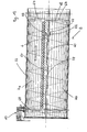
- a sieve device 2 in the form of a cylindrical drum sieve 56 shown.
- the cylindrical body has superimposed layers at least in a partial area Sieve elements 4 on.
- Each layer of a sieve element 4 forms its own Sieve layer.
- a sieve element 4 can be divided into several partial sieve elements be divided, as well as in the exemplary embodiment with the partial sieve elements 4a and 4b.
- the two partial sieve elements 4a and 4b are approximately semicircular shaped, the semicircular shape by round rolling, but also by a A plurality of angled bends can be brought about. The angled bends can act as a guide against relative rotation in the circumferential direction, if screen elements 4 lying on top of one another are correspondingly adjacent Have bends.
- the partial sieve elements 4a, 4b each have a separating edge 58, on which the partial sieve elements 4a, 4b adjoin each other.
- the partial sieve elements In the area of the separating edge 58, the partial sieve elements have 4a, 4b toothing elements 60, which during a sliding movement of the outside screen element 4 in the axial direction in a positive Connected to each other and through the contact surfaces an axial displacement movement to the other part of the screen element transfer.
- the displacement of the sieve element 4 is also by a Control edge 62 predetermined, on which formed on the partial screen elements 4a, 4b Move control tabs 64 along.
- the sieve holes 6, which are in the sieve element 4 are only shown as examples in one section.
- the two partial sieve elements 4a, 4b are on the drum below the other Sieve element 4 stretched, in which a clamping element 22 clamping webs 66th draws on each other.
- bracing can also be carried out using bolts or Similar clamping elements are made by the screen elements lying on top of each other 4 reach through.
- Screw connections others can of course also be used Connection techniques such as clamps, lever locks and the like be used.
- the adjusting device 10 can be designed that an adjustment of the size of the screen openings 8 even when vibrating and / or rotating sieve is possible.
- the adjustment device 10 acts for adjustment a sieve element 4 on an adjusting ring 68 which is fixed to the adjustable Sieve element 4 is connected.
- the function of the adjusting device 10 in cooperation with the adjusting ring 68 is shown in an enlarged view in FIG. 13.
- the adjusting device 10 consists of a lifting cylinder 12 with a piston rod 14, to which an adjusting lever 32 is connected.
- a control sleeve 70 is attached, which is slidable on a control shaft 72 is led.
- an adjusting fork 74 is attached with its fork ends encompasses the collar 68 laterally.
- guide rollers 76 are attached, whose axes of rotation are orthogonal to the direction of adjustment of the lifting cylinder 12.
- the running surfaces of the guide rollers 76 act in each case on a surface 78 of the adjusting ring 68.
- the axis of rotation of the guide rollers 76 lies orthogonal to the direction of adjustment of the hydraulic cylinder 12, but there are also others Angular positions conceivable, especially if the angular position of the tread Guide rollers 76 is adapted accordingly.
- the adjusting ring 68 can also be used as an adjustable pressure plate on the piston rod side or as U-shaped ring profile, which is attached to a sieve element 4 Guide rollers 76 act. The same can be done on the outside in the exemplary embodiment the adjusting means attached to the sieve drum also inside the drum sieve 56 be arranged, or the functional elements are so with extended lever arms equipped that parts are arranged in the end region of the screen drum 56 can.
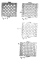
- FIG. 14 different hole patterns of sieve elements 4 are shown Have elongated holes. Each sieve element 4 has sieve holes 6, which are congruent are trained. Overlying screen holes 6 of the superimposed ones Sieve elements 4 each form one or more sieve openings 8. The together formed screen openings 8 each provide individual and by webs at least one sieve element represents 4 separate openings in the sieve, can fall through the screenings. While a sieve hole 6 by parts of a other sieve elements 4 can be completely or partially covered, is with the term Sieve opening means such an opening, through which the material to be screened through all levels Sieve elements 4 can fall freely. If you change the relative position of the superimposed Sieve elements 4 to each other, the shape and size changes of the common screen openings 8. In FIG.
- FIG. 15 screen elements 4 are shown which have screen holes 6 in a diamond shape.
- FIG. 15 A shows the largest possible with the congruent position of the sieve holes 6 Sieve opening 8, while in Figure 15 B the common sieve opening 8 is already scaled down.
- FIG. 15 C the sieve opening is reduced again, whereby a screen hole 6 of a screen element 4 in addition to the diamond-shaped reduced Sieve opening 8 forms two more common sieve openings, which consist of two there are narrow slits.
- a sieve hole 6 thus forms with three other sieve holes 6 of the other sieve element 4 from three common sieve openings 8.
- 15 D shows a position of the screen elements 4 relative to one another, in which a Sieve hole 6 of a sieve element 4 with four other sieve holes 6 of the other Siebimplantations 4 forms four common sieve openings 8.
- the different The number of holes results from the laterally offset position the holes with regard to the displacement of one or more sieve elements 4 relative to each other.
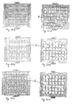
- 16 are sieve elements 4 with diagonally arranged elongated holes 6 shown. 16 A again shows the largest possible open area of the screen openings 8 shows, the area of the common screen openings 8 becomes increasingly smaller about the figures 16 B, 16 C to 16 D. In Fig. 16 D are the set Screen openings 8 of different sizes, one screen hole again with two others Sieve holes of the other sieve element 4 forms two common sieve openings 8.
- the sieve elements 4 have circular sieve holes 6. Since the Sieve holes 6 offset in the sieve elements 4, result several common sieve openings 8 in again with sufficient adjustment a screen hole 6, as shown in Figures 17 C to 17 E. While in Figure 17 C each sieve hole 6 has three common sieve openings 8, results in one Adjustment to Figure 17 D only two common sieve openings, while in the Adjustment situation, which is shown in Fig. 17 E, again three common sieve openings 8 show.
- Figures 19 A to C and 20 A to C show different hole patterns with a square or triangular formation of the screen holes 6.
- Different hole shapes are shown as examples in the hole patterns in FIGS. 14 to 20 and sizes shown.
- the variance of hole sizes and shapes can be repeated can be increased if the sieve elements 4 are adjustable not only in one direction are trained.
- FIG. 21 shows a screening device 2 from a view from above.
- Clamping element 22 has a shaft 80 running across a sieve element 4, which has eccentric 82.
- An eccentric lever 84 is fastened to the shaft 80, which can be actuated by a hydraulic cylinder 12.
- Can be used to adjust the sieve now proceed as follows: the hydraulic cylinder 12 rotates by actuation the eccentric 82 so that these at most with little pressure on the upper Sieve element 4 rest. Then the adjustable sieve element 4 in one new target position can be shifted by actuating the adjustment device 10. Then the hydraulic cylinder 12 clamps by actuating the eccentric lever 84 the eccentric 82 again firmly.
- the adjusting device 10 With a functional coupling of the actuation the adjusting device 10 with the motorized actuation of the eccentric lever 84 - for example by means of appropriate electronics - can adjust the sieve opening very gentle on the material, since the adjustment is only under if necessary, low contact pressure of the clamping elements 22 takes place.
- About the hydraulic cylinder 12 is the actuating force and thus the contact pressure with a proportional valve the eccentric 82 variably adjustable.
- the sieve clamping device described is in Figure 22 shown in a side view.
- FIG. 23 shows a cross section through sieve elements 4 lying one on top of the other.
- the sieve holes 6 are designed so that the sieve holes 6 of the upper sieve element 4 are smaller than the sieve holes 6 of the lower sieve element 4.
- a protrusion forms at the transition from the upper sieve hole 6 to the lower sieve hole 6 from which forms a cutting edge 86.
Landscapes
- Life Sciences & Earth Sciences (AREA)
- Environmental Sciences (AREA)
- Combined Means For Separation Of Solids (AREA)
- Paper (AREA)
- Crushing And Pulverization Processes (AREA)
- Disintegrating Or Milling (AREA)
Applications Claiming Priority (4)
| Application Number | Priority Date | Filing Date | Title |
|---|---|---|---|
| DE10214326 | 2002-03-28 | ||
| DE10214326 | 2002-03-28 | ||
| DE10245445A DE10245445A1 (de) | 2002-03-28 | 2002-09-27 | Motorische Verstellung eines Lochsiebs |
| DE10245445 | 2002-09-27 |
Publications (3)
| Publication Number | Publication Date |
|---|---|
| EP1348493A2 true EP1348493A2 (fr) | 2003-10-01 |
| EP1348493A3 EP1348493A3 (fr) | 2003-10-29 |
| EP1348493B1 EP1348493B1 (fr) | 2008-12-31 |
Family
ID=27675188
Family Applications (4)
| Application Number | Title | Priority Date | Filing Date |
|---|---|---|---|
| EP03007008A Expired - Lifetime EP1348493B1 (fr) | 2002-03-28 | 2003-03-27 | Réglage motorisé d'un tamis |
| EP03007070A Expired - Lifetime EP1348331B1 (fr) | 2002-03-28 | 2003-03-27 | Moisonneuse-batteuse avec tamis |
| EP03007068A Withdrawn EP1348494A3 (fr) | 2002-03-28 | 2003-03-27 | Tamis à ouvertures différentes |
| EP03007072A Expired - Lifetime EP1348495B1 (fr) | 2002-03-28 | 2003-03-27 | Tamis avec éléments de tamisage pressés l'un contre l'autre |
Family Applications After (3)
| Application Number | Title | Priority Date | Filing Date |
|---|---|---|---|
| EP03007070A Expired - Lifetime EP1348331B1 (fr) | 2002-03-28 | 2003-03-27 | Moisonneuse-batteuse avec tamis |
| EP03007068A Withdrawn EP1348494A3 (fr) | 2002-03-28 | 2003-03-27 | Tamis à ouvertures différentes |
| EP03007072A Expired - Lifetime EP1348495B1 (fr) | 2002-03-28 | 2003-03-27 | Tamis avec éléments de tamisage pressés l'un contre l'autre |
Country Status (3)
| Country | Link |
|---|---|
| EP (4) | EP1348493B1 (fr) |
| DE (9) | DE20210431U1 (fr) |
| DK (2) | DK1348493T3 (fr) |
Cited By (1)
| Publication number | Priority date | Publication date | Assignee | Title |
|---|---|---|---|---|
| CN107442400A (zh) * | 2017-08-30 | 2017-12-08 | 郑州大学 | 一种玉米籽粒除杂装置 |
Families Citing this family (49)
| Publication number | Priority date | Publication date | Assignee | Title |
|---|---|---|---|---|
| DE102004027454B4 (de) * | 2003-07-17 | 2014-06-26 | Huning Umwelttechnik Gmbh & Co. Kg | Materialspeicher zur Annahme und Abgabe von Schüttgütern |
| DE10335881A1 (de) * | 2003-08-06 | 2005-03-03 | Huning Maschinenbau Gmbh | Fördervorrichtung mit Verstellsieb |
| DE102004054275A1 (de) * | 2004-11-09 | 2006-05-11 | Bühler AG | Vorrichtung zum Trennen von körnigem Gut |
| DE202006006623U1 (de) * | 2006-04-26 | 2007-09-06 | Sägewerksanlagen GmbH | Separator zur Klassierung von durch Zerspanung hergestellten Furnierstreifen |
| DE102006045537A1 (de) * | 2006-09-25 | 2008-05-29 | Huning Maschinenbau Gmbh | Vorrichtung zur Förderung von Biomassematerialien |
| DK1903102T3 (da) | 2006-09-25 | 2011-09-19 | Huning Maschb Gmbh | Indretning til transport af biomassematerialer |
| CN100571502C (zh) * | 2008-03-04 | 2009-12-23 | 福田雷沃国际重工股份有限公司 | 收割机清选筛 |
| DE202008006019U1 (de) * | 2008-04-30 | 2009-09-10 | Smg Sportplatzmaschinenbau Gmbh | Fahrbare Vorrichtung mit einer Abtragvorrichtung |
| EP2415531B1 (fr) * | 2010-08-04 | 2014-10-15 | MTF Technik Hardy Schürfeld GmbH & Co. KG | Dispositif de séparation |
| DE102011007511A1 (de) | 2011-04-15 | 2012-10-18 | Deere & Company | Verfahren zur Einstellung einer Reinigungseinrichtung eines Mähdreschers und Reinigungseinrichtung |
| DE102011052280A1 (de) * | 2011-07-29 | 2013-01-31 | Claas Selbstfahrende Erntemaschinen Gmbh | Vermeidung von Reinigungsverlusten bei starker Seitenneigung |
| FI20116017L (fi) * | 2011-10-13 | 2013-04-14 | Salmonbay Consulting Oy | Menetelmä ja laite materiaalien, kuten kivi- ja/tai maa-ainesten seulomiseksi |
| DE102013100997A1 (de) | 2013-01-31 | 2014-07-31 | Thyssenkrupp Resource Technologies Gmbh | 1;2Verfahren und Anlage zur Mahlung von stückigem Ausgangsmaterial |
| DE102013106354A1 (de) * | 2013-06-18 | 2014-12-18 | Krones Ag | Vorrichtung sowie Verfahren zur Aufbereitung von Recyclingmaterial |
| PL232751B1 (pl) * | 2013-08-12 | 2019-07-31 | Int Tobacco Machinery Poland Spolka Z Ograniczona Odpowiedzialnoscia | Zespół do oddzielania i sposób oddzielania wybranych obiektów wadliwych z grupy obiektów stosowanych w przemyśle tytoniowym |
| EP2848323A1 (fr) * | 2013-09-13 | 2015-03-18 | Nestec S.A. | Appareil de tamisage de feuilles de thé |
| CN105123137B (zh) * | 2015-06-24 | 2017-03-29 | 金烜伊 | 一种捶打式葵花头葵花子分离设备 |
| CN105817311B (zh) * | 2016-03-25 | 2018-10-16 | 新昌县镜岭镇梅芹水果种植园 | 一种环保垃圾处理装置 |
| CN106000613B (zh) * | 2016-06-19 | 2018-04-06 | 胡侠 | 厨余垃圾处理装置 |
| WO2018053600A1 (fr) * | 2016-09-23 | 2018-03-29 | Seed Terminator Holdings PTY LTD | Broyeur à marteaux à étages multiples et système de traitement de résidu l'incorporant |
| CN108423253A (zh) * | 2017-06-19 | 2018-08-21 | 汝州市中鼎科技有限公司 | 一种生物工程包装进料设备 |
| CN107716279B (zh) * | 2017-10-17 | 2019-11-22 | 睢宁县尚鑫建筑工程有限公司 | 一种用于膨润土生产的筛网选取设备 |
| CN107855271B (zh) * | 2017-12-30 | 2019-05-03 | 新乡市振英机械设备有限公司 | 一种可调节筛孔大小的振动筛 |
| BR102018006222A2 (pt) | 2018-03-27 | 2019-10-15 | Blue Ocean Engenharia Ltda | Peneira para mineração, sistema de mineração e método de controle de uma peneira para mineração |
| CN108704837A (zh) * | 2018-04-09 | 2018-10-26 | 杨东雨 | 一种农产品加工用谷物快速筛分装置 |
| CN109107884A (zh) * | 2018-10-15 | 2019-01-01 | 淮北科源矿山机器有限公司 | 一种可调节筛孔大小的振动筛 |
| CN110280472A (zh) * | 2019-06-20 | 2019-09-27 | 广州市丹爵通讯科技有限公司 | 一种具有角度调节功能的便于维护的滚筒筛 |
| CN110560365A (zh) * | 2019-07-29 | 2019-12-13 | 重庆神斧锦泰化工有限公司 | 一种环保安全炸药生产用过滤器 |
| CN110355096A (zh) * | 2019-08-01 | 2019-10-22 | 湖南三五二环保科技有限公司 | 一种物料筛选装置 |
| CN110508485B (zh) * | 2019-08-16 | 2022-10-14 | 嘉兴琥珀科技有限公司 | 基于力传动角度变化原理的筛网运动机构 |
| DE102019128168A1 (de) * | 2019-10-18 | 2021-04-22 | Albach Maschinenbau AG | Hackvorrichtung mit einstellbarem Sieb |
| CN111070475B (zh) * | 2019-11-27 | 2021-09-07 | 徐州海天石化有限公司 | 一种用于塑料颗粒原料的筛选装置 |
| BR102020014147A2 (pt) * | 2020-07-10 | 2022-01-25 | Otalício Pacheco Da Cunha | Máquina de limpeza de produtos agrícolas por processo de centrifugação em cortina em espiral |
| CN111939623B (zh) * | 2020-07-28 | 2022-03-01 | 万江新能源集团有限公司 | 可调节过滤精度的过滤装置 |
| CN112024370A (zh) * | 2020-08-20 | 2020-12-04 | 天津大学仁爱学院 | 一种建筑施工用施工现场电控筛沙机构 |
| CN112090523B (zh) * | 2020-09-08 | 2021-09-14 | 广州卓邦科技有限公司 | 一种固体废弃物处理用球磨机 |
| US11064656B1 (en) * | 2020-11-02 | 2021-07-20 | Ronald J. Kile | Combine chaffer with chaffer dam |
| CN112517380A (zh) * | 2020-11-17 | 2021-03-19 | 湖州数越智能科技有限公司 | 一种电控式木料边角料分级筛选装置 |
| CN112893107A (zh) * | 2021-01-15 | 2021-06-04 | 江苏威拉里新材料科技有限公司 | 一种3d打印用金属粉末筛分装置 |
| CN113042362B (zh) * | 2021-05-11 | 2022-06-17 | 绍兴管维环境科技有限公司 | 一种土壤修复设备 |
| CN115193701A (zh) * | 2022-07-12 | 2022-10-18 | 中国铁建重工集团股份有限公司 | 一种可调节粒径筛分刮板机 |
| USD1032666S1 (en) | 2022-08-30 | 2024-06-25 | Calmer Holding Company, Llc | MOG limiting subassembly for combine concave |
| USD1031791S1 (en) | 2022-08-30 | 2024-06-18 | Calmer Holding Company, Llc | Straight bar concave |
| USD1031792S1 (en) | 2022-08-30 | 2024-06-18 | Calmer Holding Company, Llc | Round bar concave |
| US11877538B1 (en) | 2022-08-30 | 2024-01-23 | Calmer Holding Company, Llc | Threshing grains and legumes utilizing concaves with adjustable openings |
| USD1031793S1 (en) | 2022-08-30 | 2024-06-18 | Calmer Holding Company, Llc | Separating grate |
| CN117123467B (zh) * | 2022-11-18 | 2026-04-07 | 浙江熠东新材料科技有限公司 | 一种用于改性塑料颗粒的多级精分器 |
| USD1058613S1 (en) | 2022-11-29 | 2025-01-21 | Calmer Holding Company, Llc | Limiter plates |
| DE102023209331B3 (de) | 2023-09-25 | 2024-11-14 | Lindemann Germany GmbH | Vorrichtung zum Zerkleinern von metallischem Gut und Teilesatz |
Family Cites Families (11)
| Publication number | Priority date | Publication date | Assignee | Title |
|---|---|---|---|---|
| DE205518C (fr) * | ||||
| US121192A (en) * | 1871-11-21 | Improvement in riddles or sieves | ||
| US668737A (en) | 1900-03-26 | 1901-02-26 | Henry Loyd | Sieve for threshing-machines. |
| US1381718A (en) * | 1920-04-07 | 1921-06-14 | Lockard Alonzo | Grain-sieve |
| US2315651A (en) * | 1942-01-27 | 1943-04-06 | George W Peterson | Adjustable screen |
| US2642993A (en) * | 1950-08-07 | 1953-06-23 | Henry F Straley | Screen for threshing machines |
| DE1171196B (de) * | 1961-12-21 | 1964-05-27 | Dipl Wirtschaftsing Reinhold C | Stufen-Schuettlerbelag fuer Strohschuettler |
| DE1632892A1 (de) * | 1968-01-24 | 1971-01-21 | Wedell Wedellsborg Ove Joachim | Feinsieb fuer Maehdrescher |
| DE3739186A1 (de) * | 1987-11-19 | 1989-06-01 | Hubert Beckmann | Windsichter |
| DE4027111A1 (de) * | 1990-08-28 | 1992-03-05 | Lindemann Maschfab Gmbh | Trommelsieb sowie flachsieb |
| DE19807145C2 (de) * | 1998-02-20 | 1999-12-09 | Claas Selbstfahr Erntemasch | Mähdrescher mit Vorrichtung zur automatischen Reinigungseinstellung |
-
2002
- 2002-07-04 DE DE20210431U patent/DE20210431U1/de not_active Expired - Lifetime
- 2002-08-01 DE DE20211860U patent/DE20211860U1/de not_active Expired - Lifetime
- 2002-09-27 DE DE10245448A patent/DE10245448A1/de not_active Withdrawn
- 2002-09-27 DE DE10245445A patent/DE10245445A1/de not_active Withdrawn
- 2002-09-27 DE DE10245447A patent/DE10245447A1/de not_active Withdrawn
- 2002-09-27 DE DE10245446A patent/DE10245446A1/de not_active Ceased
-
2003
- 2003-03-27 EP EP03007008A patent/EP1348493B1/fr not_active Expired - Lifetime
- 2003-03-27 EP EP03007070A patent/EP1348331B1/fr not_active Expired - Lifetime
- 2003-03-27 DK DK03007008T patent/DK1348493T3/da active
- 2003-03-27 DK DK03007072T patent/DK1348495T3/da active
- 2003-03-27 DE DE50310988T patent/DE50310988D1/de not_active Expired - Lifetime
- 2003-03-27 EP EP03007068A patent/EP1348494A3/fr not_active Withdrawn
- 2003-03-27 EP EP03007072A patent/EP1348495B1/fr not_active Expired - Lifetime
- 2003-03-27 DE DE50312895T patent/DE50312895D1/de not_active Expired - Lifetime
- 2003-03-27 DE DE50300217T patent/DE50300217D1/de not_active Expired - Fee Related
Cited By (1)
| Publication number | Priority date | Publication date | Assignee | Title |
|---|---|---|---|---|
| CN107442400A (zh) * | 2017-08-30 | 2017-12-08 | 郑州大学 | 一种玉米籽粒除杂装置 |
Also Published As
| Publication number | Publication date |
|---|---|
| DK1348493T3 (da) | 2009-05-04 |
| DE20211860U1 (de) | 2003-07-31 |
| DE50310988D1 (de) | 2009-02-12 |
| DE20210431U1 (de) | 2003-12-18 |
| EP1348495B1 (fr) | 2010-07-21 |
| DE10245447A1 (de) | 2003-10-16 |
| DE10245448A1 (de) | 2003-10-16 |
| DE50312895D1 (de) | 2010-09-02 |
| DE10245446A1 (de) | 2003-10-16 |
| EP1348493B1 (fr) | 2008-12-31 |
| EP1348495A2 (fr) | 2003-10-01 |
| EP1348331A1 (fr) | 2003-10-01 |
| EP1348331B1 (fr) | 2004-12-29 |
| EP1348494A2 (fr) | 2003-10-01 |
| EP1348494A3 (fr) | 2003-10-29 |
| DE10245445A1 (de) | 2003-10-16 |
| DK1348495T3 (da) | 2010-11-08 |
| DE50300217D1 (de) | 2005-02-03 |
| EP1348493A3 (fr) | 2003-10-29 |
| EP1348495A3 (fr) | 2003-10-29 |
Similar Documents
| Publication | Publication Date | Title |
|---|---|---|
| EP1348493B1 (fr) | Réglage motorisé d'un tamis | |
| EP1474964A1 (fr) | Méthode et dispositif d'ajustement des ouvertures d'une surface de séparation, en particulier d'un contre-batteur d'une machine de récolte | |
| EP1408733B1 (fr) | Dispositif servant a ajuster la largeur d'ouverture du tamis de moissonneuses-batteuses | |
| DE3412139A1 (de) | Stellmechanismus | |
| DE102016112106A1 (de) | Federungsvorrichtung | |
| EP3263398B1 (fr) | Système de suspension | |
| DE2301653C3 (de) | Straßenbehandlungsgerät zur Verbesserung der Griffigkeit eines Strafien- | |
| DE4027111A1 (de) | Trommelsieb sowie flachsieb | |
| EP0106299B1 (fr) | Elément sélecteur pour semoir de précision pneumatique | |
| DE10219845C1 (de) | Siebdruckmaschine und Siebzylinder | |
| EP1052046A2 (fr) | Dispositif de serrage, p.e. pour des pièces à usiner | |
| DE2462892C2 (de) | Selbsttätige Nachstellvorrichtung für Fahrzeug-Außenbandbremsen | |
| DE2806079C2 (de) | Fräswerkzeug mit einstellbar angeordneten Schneideinsätzen | |
| EP0933271A2 (fr) | Frein à main muni d'un dispositif de rattrapage automatique pour véhicules automobiles | |
| DE3146289A1 (de) | Bremsfederkupplung fuer stellgetriebe, insbesondere von sitzstellvorrichtungen | |
| EP4040937B1 (fr) | Dispositif de travail d'un sol agricole | |
| DE102005063000A1 (de) | Elektromotorischer Linearantrieb | |
| EP1600292A2 (fr) | Dispositif pour poser une douille d'outil sur un cylindre d'outil d'une presse rotative à gaufrer ou d'une presse rotative | |
| DE69000285T2 (de) | Klemmvorrichtung. | |
| DE202010007994U1 (de) | Schnellspanner mit Doppelnocken | |
| DE19711678B4 (de) | Vorrichtung zur Regelung einer Strömung | |
| DE2023065B2 (de) | Bremsbetätigungsvorrichtung mit Bremsfedern, einem Servolüftgerät und einem hydraulischen Verzögerungszylinder | |
| DE3827236C1 (en) | Distributing device for a spreading appliance | |
| DE3531011A1 (de) | Vorrichtung fuer drehmaschinen zum fuehren oder spannen von stangenmaterial | |
| AT394255B (de) | Selbsttaetige nachstellvorrichtung fuer innenbackenbremsen |
Legal Events
| Date | Code | Title | Description |
|---|---|---|---|
| PUAI | Public reference made under article 153(3) epc to a published international application that has entered the european phase |
Free format text: ORIGINAL CODE: 0009012 |
|
| PUAL | Search report despatched |
Free format text: ORIGINAL CODE: 0009013 |
|
| AK | Designated contracting states |
Kind code of ref document: A2 Designated state(s): AT BE BG CH CY CZ DE DK EE ES FI FR GB GR HU IE IT LI LU MC NL PT RO SE SI SK TR |
|
| AX | Request for extension of the european patent |
Extension state: AL LT LV MK RO |
|
| AK | Designated contracting states |
Kind code of ref document: A3 Designated state(s): AT BE BG CH CY CZ DE DK EE ES FI FR GB GR HU IE IT LI LU MC NL PT RO SE SI SK TR |
|
| AX | Request for extension of the european patent |
Extension state: AL LT LV MK RO |
|
| 17P | Request for examination filed |
Effective date: 20040324 |
|
| AKX | Designation fees paid |
Designated state(s): BE CH DE DK GB LI |
|
| GRAP | Despatch of communication of intention to grant a patent |
Free format text: ORIGINAL CODE: EPIDOSNIGR1 |
|
| GRAS | Grant fee paid |
Free format text: ORIGINAL CODE: EPIDOSNIGR3 |
|
| GRAA | (expected) grant |
Free format text: ORIGINAL CODE: 0009210 |
|
| AK | Designated contracting states |
Kind code of ref document: B1 Designated state(s): BE CH DE DK GB LI |
|
| REG | Reference to a national code |
Ref country code: CH Ref legal event code: EP Ref country code: GB Ref legal event code: FG4D Free format text: NOT ENGLISH |
|
| REF | Corresponds to: |
Ref document number: 50310988 Country of ref document: DE Date of ref document: 20090212 Kind code of ref document: P |
|
| REG | Reference to a national code |
Ref country code: CH Ref legal event code: NV Representative=s name: SCHNEIDER FELDMANN AG PATENT- UND MARKENANWAELTE |
|
| REG | Reference to a national code |
Ref country code: DK Ref legal event code: T3 |
|
| PGFP | Annual fee paid to national office [announced via postgrant information from national office to epo] |
Ref country code: GB Payment date: 20090327 Year of fee payment: 7 |
|
| PLBE | No opposition filed within time limit |
Free format text: ORIGINAL CODE: 0009261 |
|
| STAA | Information on the status of an ep patent application or granted ep patent |
Free format text: STATUS: NO OPPOSITION FILED WITHIN TIME LIMIT |
|
| 26N | No opposition filed |
Effective date: 20091001 |
|
| GBPC | Gb: european patent ceased through non-payment of renewal fee |
Effective date: 20100327 |
|
| PG25 | Lapsed in a contracting state [announced via postgrant information from national office to epo] |
Ref country code: GB Free format text: LAPSE BECAUSE OF NON-PAYMENT OF DUE FEES Effective date: 20100327 |
|
| PGFP | Annual fee paid to national office [announced via postgrant information from national office to epo] |
Ref country code: DK Payment date: 20110311 Year of fee payment: 9 |
|
| PGFP | Annual fee paid to national office [announced via postgrant information from national office to epo] |
Ref country code: DE Payment date: 20110310 Year of fee payment: 9 Ref country code: BE Payment date: 20110324 Year of fee payment: 9 Ref country code: CH Payment date: 20110628 Year of fee payment: 9 |
|
| BERE | Be: lapsed |
Owner name: HUNING UMWELTTECHNIK G.M.B.H. + CO. KG Effective date: 20120331 |
|
| REG | Reference to a national code |
Ref country code: CH Ref legal event code: PL |
|
| REG | Reference to a national code |
Ref country code: DK Ref legal event code: EBP |
|
| PG25 | Lapsed in a contracting state [announced via postgrant information from national office to epo] |
Ref country code: CH Free format text: LAPSE BECAUSE OF NON-PAYMENT OF DUE FEES Effective date: 20120331 Ref country code: LI Free format text: LAPSE BECAUSE OF NON-PAYMENT OF DUE FEES Effective date: 20120331 Ref country code: BE Free format text: LAPSE BECAUSE OF NON-PAYMENT OF DUE FEES Effective date: 20120331 |
|
| REG | Reference to a national code |
Ref country code: DE Ref legal event code: R119 Ref document number: 50310988 Country of ref document: DE Effective date: 20121002 |
|
| PG25 | Lapsed in a contracting state [announced via postgrant information from national office to epo] |
Ref country code: DK Free format text: LAPSE BECAUSE OF NON-PAYMENT OF DUE FEES Effective date: 20120331 |
|
| PG25 | Lapsed in a contracting state [announced via postgrant information from national office to epo] |
Ref country code: DE Free format text: LAPSE BECAUSE OF NON-PAYMENT OF DUE FEES Effective date: 20121002 |