EP1348967A2 - Capteur d'accélération - Google Patents
Capteur d'accélération Download PDFInfo
- Publication number
- EP1348967A2 EP1348967A2 EP03006231A EP03006231A EP1348967A2 EP 1348967 A2 EP1348967 A2 EP 1348967A2 EP 03006231 A EP03006231 A EP 03006231A EP 03006231 A EP03006231 A EP 03006231A EP 1348967 A2 EP1348967 A2 EP 1348967A2
- Authority
- EP
- European Patent Office
- Prior art keywords
- strain gauges
- top surface
- elastic support
- support arm
- mass portion
- Prior art date
- Legal status (The legal status is an assumption and is not a legal conclusion. Google has not performed a legal analysis and makes no representation as to the accuracy of the status listed.)
- Withdrawn
Links
- 230000001133 acceleration Effects 0.000 title claims abstract description 183
- 239000000758 substrate Substances 0.000 abstract description 21
- XUIMIQQOPSSXEZ-UHFFFAOYSA-N Silicon Chemical compound [Si] XUIMIQQOPSSXEZ-UHFFFAOYSA-N 0.000 abstract description 14
- 230000035945 sensitivity Effects 0.000 abstract description 14
- 229910052710 silicon Inorganic materials 0.000 abstract description 14
- 239000010703 silicon Substances 0.000 abstract description 14
- 239000004065 semiconductor Substances 0.000 abstract description 9
- VYPSYNLAJGMNEJ-UHFFFAOYSA-N Silicium dioxide Chemical compound O=[Si]=O VYPSYNLAJGMNEJ-UHFFFAOYSA-N 0.000 description 26
- 239000013078 crystal Substances 0.000 description 15
- 229910052681 coesite Inorganic materials 0.000 description 13
- 229910052906 cristobalite Inorganic materials 0.000 description 13
- 239000000377 silicon dioxide Substances 0.000 description 13
- 229910052682 stishovite Inorganic materials 0.000 description 13
- 229910052905 tridymite Inorganic materials 0.000 description 13
- 238000000034 method Methods 0.000 description 9
- 238000005530 etching Methods 0.000 description 7
- 238000004519 manufacturing process Methods 0.000 description 5
- KRHYYFGTRYWZRS-UHFFFAOYSA-N Fluorane Chemical compound F KRHYYFGTRYWZRS-UHFFFAOYSA-N 0.000 description 4
- 238000001312 dry etching Methods 0.000 description 4
- 230000000694 effects Effects 0.000 description 4
- 239000012535 impurity Substances 0.000 description 4
- 238000005452 bending Methods 0.000 description 3
- 238000001514 detection method Methods 0.000 description 3
- 238000005516 engineering process Methods 0.000 description 3
- 238000009413 insulation Methods 0.000 description 2
- 229920002120 photoresistant polymer Polymers 0.000 description 2
- 238000001039 wet etching Methods 0.000 description 2
- 229910000838 Al alloy Inorganic materials 0.000 description 1
- ZOXJGFHDIHLPTG-UHFFFAOYSA-N Boron Chemical compound [B] ZOXJGFHDIHLPTG-UHFFFAOYSA-N 0.000 description 1
- RYGMFSIKBFXOCR-UHFFFAOYSA-N Copper Chemical compound [Cu] RYGMFSIKBFXOCR-UHFFFAOYSA-N 0.000 description 1
- XAGFODPZIPBFFR-UHFFFAOYSA-N aluminium Chemical compound [Al] XAGFODPZIPBFFR-UHFFFAOYSA-N 0.000 description 1
- 229910052782 aluminium Inorganic materials 0.000 description 1
- 230000003321 amplification Effects 0.000 description 1
- 229910052796 boron Inorganic materials 0.000 description 1
- 229910052802 copper Inorganic materials 0.000 description 1
- 239000010949 copper Substances 0.000 description 1
- 230000007547 defect Effects 0.000 description 1
- 238000009792 diffusion process Methods 0.000 description 1
- 238000005247 gettering Methods 0.000 description 1
- 239000011521 glass Substances 0.000 description 1
- 230000005484 gravity Effects 0.000 description 1
- BHEPBYXIRTUNPN-UHFFFAOYSA-N hydridophosphorus(.) (triplet) Chemical compound [PH] BHEPBYXIRTUNPN-UHFFFAOYSA-N 0.000 description 1
- 239000004615 ingredient Substances 0.000 description 1
- 239000012212 insulator Substances 0.000 description 1
- 238000005468 ion implantation Methods 0.000 description 1
- 238000003475 lamination Methods 0.000 description 1
- 238000012886 linear function Methods 0.000 description 1
- 239000002075 main ingredient Substances 0.000 description 1
- 230000004048 modification Effects 0.000 description 1
- 238000012986 modification Methods 0.000 description 1
- 238000003199 nucleic acid amplification method Methods 0.000 description 1
- 238000004806 packaging method and process Methods 0.000 description 1
- 238000001259 photo etching Methods 0.000 description 1
- 229920000642 polymer Polymers 0.000 description 1
Images


Classifications
-
- G—PHYSICS
- G01—MEASURING; TESTING
- G01P—MEASURING LINEAR OR ANGULAR SPEED, ACCELERATION, DECELERATION, OR SHOCK; INDICATING PRESENCE, ABSENCE, OR DIRECTION, OF MOVEMENT
- G01P15/00—Measuring acceleration; Measuring deceleration; Measuring shock, i.e. sudden change of acceleration
-
- G—PHYSICS
- G01—MEASURING; TESTING
- G01P—MEASURING LINEAR OR ANGULAR SPEED, ACCELERATION, DECELERATION, OR SHOCK; INDICATING PRESENCE, ABSENCE, OR DIRECTION, OF MOVEMENT
- G01P15/00—Measuring acceleration; Measuring deceleration; Measuring shock, i.e. sudden change of acceleration
- G01P15/02—Measuring acceleration; Measuring deceleration; Measuring shock, i.e. sudden change of acceleration by making use of inertia forces using solid seismic masses
- G01P15/08—Measuring acceleration; Measuring deceleration; Measuring shock, i.e. sudden change of acceleration by making use of inertia forces using solid seismic masses with conversion into electric or magnetic values
- G01P15/12—Measuring acceleration; Measuring deceleration; Measuring shock, i.e. sudden change of acceleration by making use of inertia forces using solid seismic masses with conversion into electric or magnetic values by alteration of electrical resistance
- G01P15/123—Measuring acceleration; Measuring deceleration; Measuring shock, i.e. sudden change of acceleration by making use of inertia forces using solid seismic masses with conversion into electric or magnetic values by alteration of electrical resistance by piezo-resistive elements, e.g. semiconductor strain gauges
-
- G—PHYSICS
- G01—MEASURING; TESTING
- G01P—MEASURING LINEAR OR ANGULAR SPEED, ACCELERATION, DECELERATION, OR SHOCK; INDICATING PRESENCE, ABSENCE, OR DIRECTION, OF MOVEMENT
- G01P15/00—Measuring acceleration; Measuring deceleration; Measuring shock, i.e. sudden change of acceleration
- G01P15/18—Measuring acceleration; Measuring deceleration; Measuring shock, i.e. sudden change of acceleration in two or more dimensions
-
- G—PHYSICS
- G01—MEASURING; TESTING
- G01P—MEASURING LINEAR OR ANGULAR SPEED, ACCELERATION, DECELERATION, OR SHOCK; INDICATING PRESENCE, ABSENCE, OR DIRECTION, OF MOVEMENT
- G01P15/00—Measuring acceleration; Measuring deceleration; Measuring shock, i.e. sudden change of acceleration
- G01P15/02—Measuring acceleration; Measuring deceleration; Measuring shock, i.e. sudden change of acceleration by making use of inertia forces using solid seismic masses
- G01P15/08—Measuring acceleration; Measuring deceleration; Measuring shock, i.e. sudden change of acceleration by making use of inertia forces using solid seismic masses with conversion into electric or magnetic values
- G01P2015/0805—Measuring acceleration; Measuring deceleration; Measuring shock, i.e. sudden change of acceleration by making use of inertia forces using solid seismic masses with conversion into electric or magnetic values being provided with a particular type of spring-mass-system for defining the displacement of a seismic mass due to an external acceleration
- G01P2015/0822—Measuring acceleration; Measuring deceleration; Measuring shock, i.e. sudden change of acceleration by making use of inertia forces using solid seismic masses with conversion into electric or magnetic values being provided with a particular type of spring-mass-system for defining the displacement of a seismic mass due to an external acceleration for defining out-of-plane movement of the mass
- G01P2015/084—Measuring acceleration; Measuring deceleration; Measuring shock, i.e. sudden change of acceleration by making use of inertia forces using solid seismic masses with conversion into electric or magnetic values being provided with a particular type of spring-mass-system for defining the displacement of a seismic mass due to an external acceleration for defining out-of-plane movement of the mass the mass being suspended at more than one of its sides, e.g. membrane-type suspension, so as to permit multi-axis movement of the mass
Definitions
- the present invention relates to an acceleration sensor for detecting acceleration, which is used for toys, automobiles, aircrafts, portable terminals and the like, and particularly to an acceleration sensor that can be produced using a semiconductor technology.
- Acceleration sensors utilizing a change in physical quantity such as a piezo resistance effect and a change in electrostatic capacity have been developed and commercialized. These acceleration sensors can be widely used in various fields, but recently, such small-sized acceleration sensors as can detect the acceleration in multi-axial directions at one time with high sensitivity are demanded.
- a piezo resistance effect type semiconductor acceleration sensor in which a thin elastic support portion is provided at a silicon single crystal substrate, and the stress applied to the thin elastic support portion is converted into an electric signal by a strain gauge, for example, a piezo resistance effect element, to be an output.
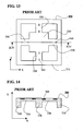
- the acceleration sensor 500 has elastic support arms 530 each of a beam structure, constituted by a thin portion of a silicon single crystal substrate.
- a mass portion 520 in a center, which is constituted by a thick portion of a silicon single crystal substrate, and a frame 510 in a periphery thereof are connected by the elastic support arms 530.
- a plurality of strain gauges 560 are formed in each axial direction on the elastic support arms 530.
- the sensor 500 has the mass portion 520 constituted by the thick portion of the silicon single crystal substrate, a frame 510 placed to surround the mass portion 520, and two pairs of elastic support arms 530 in a beam form, which are perpendicular to each other and each constituted by the thin portion of the silicon single crystal substrate to bridge the mass portion 520 and the frame 510.
- the mass portion moves in the frame to deform the elastic support arms, and thus the deformation is detected by the strain gauges provided on the elastic support arms to obtain the acceleration that works.
- the acceleration in a Y-axis direction is measured by the four strain gauges 560 provided on the elastic support arms extending in the X-axis direction
- the acceleration in a Y-axis direction is measured by the four strain gauges 560 provided on the elastic support arms extending in the Y-axis direction.
- the acceleration in a Z-axis direction is measured by means of all the strain gauges 560.
- strain gauges for detecting Z-axis acceleration are different from strain gauges for detecting X-axis acceleration, while the Z-axis strain gauges are located on elastic support arms in X-axis direction in the same way as X-axis strain gauges.
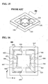
- an acceleration sensor 600 has a mass portion 620 in a center, a thick frame 610 around it, and elastic support arms 631, 632, 633 and 634 for bridging the mass portion 620 and the thick frame 610. Since the elastic support arms 631, 632, 633 and 634 are thin, the mass portion deforms the elastic support arms when acceleration acts on the mass portion 620. Large deformation of each of the elastic support arms occurs to end portions of the elastic support arms, that is, connecting portions of an edge of a top surface of the mass portion and the elastic support arms, and connecting portions of inside edges of a top surface of the thick frame and the elastic support arms. In order to enhance the sensitivity of the acceleration sensor, strain gauges are attached at the portions of the elastic support arms, which are deformed most by the acceleration.
- strain gauges 661, 662, 663 and 664 for detecting acceleration in the X-axis direction, and strain gauges 681, 682, 683 and 684 for detecting acceleration in the Z-axis direction are placed on the elastic support arms 631 and 633. It is generally known that there exists the relationship as shown in FIG. 17 between sensitivities of the X-axis strain gauge and the Z-axis strain gauge (output with respect to acceleration 1 G, and drive voltage 1 V).
- the acceleration sensor 600 shown in FIG. 16 is produced with use of a Si single crystal substrate which is generally used in semiconductor fabrication, thickness of the Si single crystal substrate is 625 ⁇ m or 525 ⁇ m, and therefore as can be seen from FIG. 17, the sensitivity of the Z-axis strain gauge becomes larger than that of the X-axis strain gauge. If the sensitivities of the Z-axis strain gauge and the X-axis strain gauge are about the same, the amplifiers having about the same output amplification factors can be used for the Z-axis strain gauge and the X-axis strain gauge.
- the acceleration sensor 600 In order to make the sensitivity of the Z-axis strain gauge the same as that of the X-axis strain gauge, it is suitable to make the acceleration sensor 600 with use of the Si single crystal substrate of thickness of about 800 ⁇ m, but such a thick Si single crystal substrate as this has to be especially prepared only for this acceleration sensor, and this increases the cost of the acceleration sensor.
- An acceleration sensor comprises a mass portion which can be provided in a center of the acceleration sensor and can have a top surface. Further, a thick frame surrounding the mass portion with a predetermined distance from the mass portion and having a top surface can be provided. More further a plurality of elastic support arms each extending (e.g., in X-axis direction) from an edge of the top surface of the mass portion can be provided. The plurality of elastic support arms can be arranged bridging the top surface edge of the mass portion and an inside edge of the top surface of the thick frame and hanging the mass portion inside of the thick frame.
- two first strain gauges can be provided disposed on a top surface of each of the elastic support arms with a distance from each other along the elastic support arm extending (e.g., in X-axis direction).
- the two first strain gauges can extend in the direction of the elastic support arm extending (e.g., in X-axis direction).
- Two second strain gauges can further be provided disposed on the top surface of the elastic support arm having the two first strain gauges and with a distance different from the first strain gauge distance between the two second strain gauges along the elastic support arm (e.g., in X-axis direction).
- the two second strain gauges can extend in the direction of the elastic support arm extending (e.g., in X-axis direction).
- the two first strain gauges can detect an acceleration in the direction of the elastic support arm extending (e.g., in X-axis direction) and the two second strain gauges can detect an acceleration in the direction (Z-axis direction) perpendicular to the top surface of the mass portion.
- one of the two first strain gauges may be disposed entirely on the top surface of the elastic support arm so that an end of the one of the first strain gauges is substantially located at the inside edge of the top surface of the thick frame.
- the other of the two first strain gauges may be disposed entirely on the top surface of the elastic support arm so that an end of the other of the first strain gauges is substantially located at the top surface edge of the mass portion.
- One of the two second strain gauges can be desirably disposed, bridging the top surface of the thick frame and the top surface of the elastic support arm so that one end of the one of the second strain gauges is located on the top surface of the elastic support arm and the other end of the one of the second strain gauges is located on the top surface of the thick frame.
- the other of the two second strain gauges can be desirably disposed, bridging the top surface of the mass portion and the top surface of the elastic support arm so that one end of the other of the second strain gauges is located on the top surface of the mass portion and the other end of the other of the second strain gauges is located on the top surface of the elastic support arm.
- the distance between the two second strain gauges can be longer by 0.4 to 1.2 times a length of the strain gauges than the distance between the two first strain gauges. More further, the distance between the two second strain gauges can be longer by 0.6 to 1.0 times a length of the strain gauges than the distance between the two first strain gauges.
- the two second strain gauges may be disposed entirely on the top surface of the elastic support arm so that all ends of the two second strain gauges are apart from ends of the elastic support arm.
- the distance between the two second strain gauges can be desirably shorter by 1.0 to 1.8 times a length of the strain gauges than the distance between the two first strain gauges. More further, the distance between the two second strain gauges can be shorter by 1.2 to 1.6 times a length of the strain gauges than the distance between the two first strain gauges.
- An acceleration sensor comprises a mass portion which can be provided in a center of the acceleration sensor and can have a top surface. Further a thick frame can be provided surrounding the mass portion with a predetermined distance from the mass portion and having a top surface. More further, two first elastic support arms extending in parallel and in opposite directions to each other (e.g., in +X-axis and -X-axis directions) from opposite edges of the top surface of the mass portion can be provided. The two first elastic support arms can be arranged bridging the top surface edges of the mass portion and inside edges of the top surface of the thick frame and hanging the mass portion inside of the thick frame.
- first strain gauges can be provided disposed on a top surface of each of the first elastic support arms with a distance from each other along the first elastic support arm extending (e.g., in +X-axis/-X-axis direction).
- the two first strain gauges can extend in the direction of the first elastic support arm extending (e.g., in +X-axis/-X-axis direction).
- One of the two first strain gauges can be disposed entirely on the top surface of the first elastic support arm so that an end of the one of the two first strain gauges is located substantially at the inside edge of the top surface of the thick frame.
- the other of the two first strain gauges can be disposed entirely on the top surface of the first elastic support arm so that an end of the other of the two first strain gauges is located substantially at the top surface edge of the mass portion.
- Two second strain gauges can further be provided disposed on the top surface of each of the first elastic support arms with a distance longer by 0.4 to 1.2 times a length of the strain gauges than the distance between the two first strain gauges along the first elastic support arms extending (e.g., in +X-axis/-X-axis direction).
- the two second strain gauges can extend in the direction of the first elastic support arm (e.g., in +X-axis/-X-axis direction).
- One of the two second strain gauges can be disposed, bridging the top surface of the thick frame and the top surface of the first elastic support arm so that one end of the one of the two second strain gauges is located on the top surface of thick frame and the other end of the one of the two second strain gauges is located on the top surface of the first elastic support arm.
- the other of the two second strain gauges can be disposed, bridging the top surface of the mass portion and the top surface of the first elastic support arm so that one end of the other of the two second strain gauges is located on the top surface of the mass portion and the other end of the other of the two second strain gauges is located on the top surface of the first elastic support arm.
- Two second elastic support arms can extend in parallel and in opposite directions to each other (e.g., in +Y-axis and -Y-axis directions) from other opposite edges of the top surface of the mass portion.
- the two second elastic support arms can be arranged bridging the other top surface edges of the mass portion and other inside edges of the top surface of the thick frame and hanging the mass portion inside of the thick frame.
- Two third strain gauges can be disposed on a top surface of each of the second elastic support arms with a distance from each other along the second elastic support arm extending (e.g., in +Y-axis/-Y-axis direction), and extending in the direction of the second elastic support arm extending (e.g., in +Y-axis/-Y-axis direction).
- One of the two third strain gauges can be disposed entirely on the top surface of the second elastic support arm so that an end of the one of the two third strain gauges is located substantially at the other inside edge of the top surface of the thick frame.
- the other of the two third strain gauges can be disposed entirely on the top surface of the second elastic support arm so that an end of the other of the two third strain gauges is located substantially at the top surface edge of the mass portion.
- the two first strain gauges can detect an acceleration in the direction of the first elastic support arm extending (e.g., in X-axis direction), the two second strain gauges can detect an acceleration in the direction (Z-axis direction) perpendicular to the top surface of the mass portion and the two third strain gauges can detect an acceleration in the direction of the second elastic support arm extending (e.g., in Y-axis direction).
- An acceleration sensor of the invention comprises a mass portion which can be provided in a center of the acceleration sensor and can have a top surface. Further a thick frame surrounding the mass portion with a predetermined distance from the mass portion and having a top surface can be provided. More further, two first elastic support arms extending in parallel and in opposite directions to each other (e.g., in +X-axis and -X-axis directions) from opposite edges of the top surface of the mass portion can be provided. The two first elastic support arms can be arranged bridging the top surface edges of the mass portion and inside edges of the top surface of the thick frame and hanging the mass portion inside of the thick frame.
- first strain gauges can be disposed on a top surface of each of the first elastic support arms with a distance from each other along the first elastic support arm extending (e.g., in +X-axis/-X-axis direction).
- the two first strain gauges can extend in the direction of the first elastic support arm extending (e.g., in +X-axis/-X-axis direction).
- One of the two first strain gauges can be disposed entirely on the top surface of the first elastic support arm so that an end of the one of the two first strain gauges is located substantially at the inside edge of the top surface of the thick frame.
- the other of the two first strain gauges can be disposed entirely on the top surface of the first elastic support arm so that an end of the other of the two first strain gauges is located substantially at the top surface edge of the mass portion.
- Two second strain gauges can be disposed on the top surface of each of the first elastic support arms with a distance shorter by 1.0 to 1.8 times a length of the strain gauges than the distance between the two first strain gauges along the first elastic support arms extending (e.g., in +X-axis/-X-axis direction).
- the two second strain gauges can extend in the direction of the first elastic support arm (e.g., in +X-axis/-X-axis direction).
- the two second strain gauges can be disposed entirely on the top surface of the first elastic support arm so that all ends of the two second strain gauges are apart from all ends of the top surface of the first elastic support arm.
- Two second elastic support arms can be arranged extending in parallel and in opposite directions to each other (e.g., in +Y-axis and -Y-axis directions) from other opposite edges of the top surface of the mass portion, bridging the other top surface edges of the mass portion and other inside edges of the top surface of the thick frame and hanging the mass portion inside of the thick frame.
- Two third strain gauges can be disposed on a top surface of each of the second elastic support arms with a distance from each other along the second elastic support arm extending (e.g., in +Y-axis/-Y-axis direction).
- the two third strain gauges can extend in the direction of the second elastic support arm extending (e.g., in +Y-axis/-Y-axis direction).
- One of the two third strain gauges can be disposed entirely on the top surface of the second elastic support arm so that an end of the one of the two third strain gauges is located substantially at the other inside edge of the top surface of the thick frame.
- the other of the two third strain gauges can be disposed entirely on the top surface of the second elastic support arm so that an end of the other of the two third strain gauges is located substantially at the top surface edge of the mass portion.
- the two first strain gauges can detect an acceleration in the direction of the first elastic support arm extending (e.g., in X-axis direction)
- the two second strain gauges can detect an acceleration in the direction (Z-axis direction) perpendicular to the top surface of the mass portion
- the two third strain gauges can detect an acceleration in the direction of the second elastic support arm extending (e.g., in Y-axis direction).
- An acceleration sensor of the invention comprises a mass portion which can be provided in a center of the acceleration sensor and can have a top surface. Further a thick frame surrounding the mass portion with a predetermined distance from the mass portion and having a top surface can be provided. More further, a plurality of elastic support arms each extending (e.g., in X-axis direction) from an edge of the top surface of the mass portion can be provided. The plurality of elastic support arms can be arranged bridging the top surface edge of the mass portion and an inside edge of the top surface of the thick frame and hanging the mass portion inside of the thick frame.
- Two first strain gauges can be disposed on a top surface of each of the elastic support arms with a distance from each other along the elastic support arm extending (e.g., in X-axis direction).
- the two first strain gauges can extend in the direction of the elastic support arm extending (e.g., in X-axis direction).
- Two second strain gauges can be disposed on the top surface of the elastic support arm having the two first strain gauges and at an angle with the direction of the elastic support arm extending (e.g., X-axis).
- the two first strain gauges can detect an acceleration in the direction of the elastic support arm extending (e.g., in X-axis direction) and -the two second strain gauges can detect an acceleration in the direction (Z-axis direction) perpendicular to the top surface of the mass portion.
- one of the two first strain gauges and/or one of the two second strain gauges may be disposed entirely on the top surface of the elastic support arm so that an end of each of the one of the two first strain gauges.
- the one of the two second strain gauges can be substantially located at the inside edge of the top surface of the thick frame.
- the other of the two first strain gauges and the other of the two second strain gauges may be disposed entirely on the top surface of the elastic support arm so that an end of each of the other of the two first strain gauges and the other of the two second strain gauges is substantially located at the top surface edge of the mass portion.
- Each of the two second strain gauges can be disposed at an angle of 10 to 30 degrees or 65 to 90 degrees with the direction of the elastic support arm extending (e.g., X-axis).
- An acceleration sensor of the invention comprises a mass portion which can be provided in a center of the acceleration sensor and can have a top surface. Further a thick frame surrounding the mass portion with a predetermined distance from the mass portion and having a top surface can be provided. Two first elastic support arms can further be provided extending in parallel and in opposite directions to each other (e.g., in +X-axis and -X-axis directions) from opposite edges of the top surface of the mass portion. The two first elastic support arms can be arranged bridging the top surface edges of the mass portion and inside edges of the top surface of the thick frame and hanging the mass portion inside of the thick frame.
- Two first strain gauges can be disposed on a top surface of each of the first elastic support arms with a distance from each other along the first elastic support arm extending (e.g., in X-axis direction).
- the two first elastic support arms can extend in the direction of the first elastic support arm extending (e.g., in X-axis direction).
- Two second strain gauges can be disposed on the top surface of each of the first elastic support arms at an angle of 10 to 30 degrees or 65 to 90 degrees with the direction (e.g., X-axis) of the first elastic support arm extending.
- One of the two first strain gauges and/or one of the two second strain gauges can be disposed entirely on the top surface of the first elastic support arm so that an end of each of the one of the two first strain gauges and the one of the two second strain gauges is located substantially at the inside edge of the top surface of the thick frame.
- the other of the two first strain gauges and/or the other of the two second strain gauges can be disposed entirely on the top surface of the first elastic support arm so that an end of each of the other of the two first strain gauges and/or the other of the two second strain gauges is located substantially at the top surface edge of the mass portion.
- Two second elastic support arms can extend in parallel and in opposite directions to each other (e.g., in +Y-axis and -Y-axis directions) from other opposite edges of the top surface of the mass portion.
- the two second elastic support arms can be arranged bridging the other top surface edges of the mass portion and other inside edges of the top surface of the thick frame and hanging the mass portion inside of the thick frame.
- Two third strain gauges can be disposed on a top surface of each of the second elastic support arms with a distance from each other along the second elastic support arm extending (e.g., in Y-axis direction).
- the two third strain gauges can extend in the direction of the second elastic support arm extending (e.g., in Y-axis direction).
- One of the two third strain gauges can be disposed entirely on the top surface of the second elastic support arm so that an end of the one of the two third strain gauges is located substantially at the other inside edge of the top surface of the thick frame.
- the other of the two third strain gauges can be disposed entirely on the top surface of the second elastic support arm so that an end of the other of the two third strain gauges is located substantially at the top surface edge of the mass portion.
- the two first strain gauges can detect an acceleration in the direction of the first elastic support arm extending (e.g., in X-axis direction), the two second strain gauges can detect an acceleration in the direction (Z-axis direction) perpendicular to the top surface of the mass portion and the two third strain gauges can detect an acceleration in the direction of the second elastic support arm extending (e.g., in Y-axis direction).
- an acceleration sensor of the invention comprises a mass portion which can be provided in a center of the acceleration sensor and can have a top surface. Further a thick frame surrounding the mass portion with a predetermined distance from the mass portion and having a top surface can be provided. More further, a plurality of elastic support arms each extending (e.g., in X-axis direction) from an edge of the top surface of the mass portion can be provided. The plurality of elastic support arms can be arranged bridging the top surface edge of the mass portion and an inside edge of the top surface of the thick frame and hanging the mass portion inside of the thick frame.
- Two first strain gauges can be disposed on a top surface of each of the elastic support arms with a distance from each other along the elastic support arm extending (e.g., in X-axis direction), and extending in the direction of the elastic support arm extending (e.g., in X-axis direction).
- Two second strain gauges can be disposed on the top surface of the elastic support arm having the two first strain gauges and with a distance different from the first strain gauge distance between the two second strain gauges along the elastic support arm (e.g., in X-axis direction).
- the two second strain gauges can extend at an angle with the direction of the elastic support arm extending (e.g., X-axis).
- the two first strain gauges can detect an acceleration in the direction of the elastic support arm extending (e.g., in X-axis direction) and the two second strain gauges can detect an acceleration in the direction (Z-axis direction) perpendicular to the top surface of the mass portion.
- one of the two first strain gauges and/or one of the two second strain gauges can be disposed entirely on the top surface of the elastic support arm so that an end of each of the one of the two first strain gauges and/or the one of the two second strain gauges is substantially located at the inside edge of the top surface of the thick frame.
- the other of the two first strain gauges and/or the other of the two second strain gauges can be disposed entirely on the top surface of the elastic support arm so that an end of each of the other of the two first strain gauges and/or the other of the two second strain gauges is substantially located at the top surface edge of the mass portion.
- Each of the two second strain gauges can be disposed at an angle of 10 to 30 degrees or 65 to 90 degrees with the direction of the elastic support arm extending (e.g., X-axis).
- the distance between the two second strain gauges can be longer by 0.4 to 1.2 times a length of the strain gauges than the distance between the two first strain gauges.
- the distance between the two second strain gauges can be longer by 0.6 to 1.0 times a length of the strain gauges than the distance between the two first strain gauges.
- the distance between the two second strain gauges can also be shorter by 1.0 to 1.8 times a length of the strain gauges than the distance between the two first strain gauges.
- the distance between the two second strain gauges can be by 1.2 to 1.6 times a length of the strain gauges than the distance between the two first strain gauges.
- FIG. 1 is a plan view showing an acceleration sensor of an EXAMPLE of the present invention
- FIG. 2 is a sectional view of the acceleration sensor in FIG. 1 taken along the line II-II in FIG. 1;
- FIG. 3 is an enlarged plan view showing an elastic support arm of the acceleration sensor of an EXAMPLE of the present invention
- FIG. 4 is a graph showing a relationship between ratio of Z-axis piezoresistor output to X-axis piezoresistor output and difference between Z-axis piezoresistor distance and X-axis piezoresistor distance in the acceleration sensor of an EXAMPLE of the present invention
- FIG. 5 is a plan view showing an acceleration sensor of a further EXAMPLE of the present invention.
- FIG. 6 is an enlarged plan view showing an elastic support arm of the acceleration sensor of a further EXAMPLE of the present invention.
- FIG. 7 is a graph showing ratio of Z-axis piezoresistor output to X-axis piezoresistor output vs. difference between Z-axis piezoresistor distance and X-axis piezoresistor distance in the acceleration sensor of a further EXAMPLE of the present invention
- FIG. 8 is a plan view showing an acceleration sensor of a more further EXAMPLE of the present invention.
- FIG. 9 is an enlarged plan view showing an elastic support arm of the acceleration sensor of a more further EXAMPLE of the present invention.
- FIG. 10 is a graph showing ratio of Z-axis piezoresistor output to X-axis piezoresistor output vs. angle of Z-axis piezoresistor with X-axis in the acceleration sensor of EXAMPLE 3 of the present invention
- FIG. 11 is a graph showing ratio of Z-axis piezoresistor output to X-axis piezoresistor output vs. angle of Z-axis piezoresistor with X-axis in the acceleration sensor of EXAMPLE 3 of the present invention
- FIGS. 12A through 12E are explanatory views of a production process of the acceleration sensor of the present invention.
- FIG. 13 is a plan view showing an acceleration sensor disclosed in a Japanese Laid-Open Patent
- FIG. 14 is a sectional view of the acceleration sensor in FIG. 13 taken along the line XIV-XIV in FIG. 13;
- FIG. 15 is a perspective view of the acceleration sensor in FIG. 13;
- FIG. 16 is a plan view of an acceleration sensor proposed in a co-pending patent application by the applicant.
- FIG. 17 is a graph showing X-axis strain gauge sensitivity vs. mass portion thickness and Y-axis strain gauge sensitivity vs. mass portion thickness in the acceleration sensor proposed in a co-pending patent application.
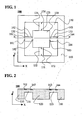
- FIG. 1 is a plan view of the acceleration sensor.
- FIG. 2 is a sectional view taken along the line II-II in FIG. 1
- FIG. 3 is an enlarged plan view showing an elastic support arm of the acceleration sensor
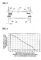
- FIG. 4' is a graph showing a relationship between the ratio of Z-axis piezoresistor output to X-axis piezoresistor output and difference between Z-axis piezoresistor distance and X-axis piezoresistor distance in the acceleration sensor of the present invention.
- the acceleration sensor of the present invention uses a silicon single crystal substrate with a SOI layer being formed via a SiO 2 insulation layer, namely, a SOI wafer, in order to make it possible to control the thickness of elastic support arms with high precision.
- the SOI is an abbreviation of a Silicon On Insulator.
- an accelerator sensor 100 of the present invention four L-shaped through-holes 150 in a square-shaped silicon single crystal substrate of the same size as a frame 110 are made, whereby a mass portion 120 in a center, a thick frame 110 around it, and support arms placed between them are formed, and by making the portions of the support arms thin to make elastic support arms 131, 132, 133 and 134.
- the acceleration sensor 100 has strain gauges (in the explanation below, a "piezoresistor” as an example of a strain gauge is used, and therefore they are called “piezoresistors”) 161 to 164, 171 to 174 and 181 to 184, which are placed on the elastic support arms to be corresponding to two perpendicular detection axes (axes X and Y) and a detection axis (axis Z) perpendicular to a top surface of the acceleration sensor, with four stain gauges for each axis. Namely, on the elastic support arms 131 and 133 extending in the X-axis direction, pairs of piezoresistors 161 and 162, and 163 and 164 are provided respectively to detect acceleration in the X-axis direction.
- Pairs of the piezoresistors 171 and 172, and 173 and 174 are provided respectively on the elastic support arms 132 and 134 extending in the Y-axis direction to detect acceleration in the Y-axis direction. Further, pairs of piezoresistors 181 and 182, and 183 and 184 are provided respectively on the elastic support arms 131 and 133 extending in the X-axis direction to detect acceleration in the Z-axis direction.
- the acceleration in the Z-axis direction is detected with the piezoresistors provided on the elastic support arms 131 and 133, but the element detecting the acceleration in the Z-axis direction may be provided on the elastic support arms 132 and 134.
- the four piezoresistors for detecting the acceleration in each axis direction construct separate full bridge detection circuits.
- the two piezoresistors 161 and 162 for detecting the acceleration in the X-axis direction which are provided on the elastic support arm 131, are aligned in the X-axis direction and extend in the X-axis direction.
- the two piezoresistors are at each end of the elastic support arm 131, and respective ends of the two piezoresistors are located on a border between an inside edge of a top surface of the thick frame 110 and the elastic support arm 131 and on a border between the elastic support arm 131 and a top surface edge of the mass portion 120.
- the two piezoresistors 163 and 164 for detecting the acceleration in the X-axis direction which are provided on the elastic support arm 133, are aligned in the X-axis direction and extend in the X-axis direction.
- the two piezoresistors are at each end of the elastic support arm 133, and respective ends of the two piezoresistors are located on a border between a top surface edge of the mass portion 120 and the elastic support arm 133 and on a border between the elastic support arm 133 and an inside edge of the top surface of the thick frame 110.
- the two piezoresistors 161 and 162 on the elastic support arm 131 are separated from each other by a distance which is the result of subtracting the piezoresistor length L from the length of the elastic support arm 131.
- the two piezoresistors 163 and 164 on the elastic support arm 133 are separated from each other by a distance which is the result of subtracting the piezoresistor length L from the length of the elastic support arm 133.
- the piezoresistors 171 to 174 for detecting the acceleration in the Y-axis direction are aligned in the Y-axis direction and extend in the Y-axis direction. Out of them, the piezoresistors 171 and 172 are at each end of the elastic support arm 132, and are provided on the elastic support arm 132 so that respective ends of the piezoresistors 171 and 172 are on a border between an inside edge of the top surface of the thick frame 110 and the elastic support arm 132 and on a border between the elastic support arm 132 and a top surface edge of the mass portion 120.
- the piezoresistors 173 and 174 are at each end of the elastic support arm 134, and are provided on the elastic support arm 134 so that respective ends of the piezoresistors 173 and 174 are on a border between a top surface edge of the mass portion 120 and the elastic support arm 134 and on a border between the elastic support arm 134 and an inside edge of the top surface of the thick frame 110.
- the two piezoresistors 171 and 172 on the elastic support arm 132 are separated from each other by a distance which is the result of subtracting the piezoresistor length L from the length of the elastic support arm 132.
- the two piezoresistors 173 and 174 on the elastic support arm 134 are separated from each other by a distance which is the result of subtracting the piezoresistor length L from the elastic support arm 134.
- the piezoresistors 181 and 182 for detecting the acceleration in the Z-axis direction, which are on the elastic support arm 131, are aligned in the X-axis direction and extend in the X-axis direction.
- the piezoresistor 181 is provided to extend from the top surface of the thick frame onto the elastic support arm 131, and the piezoresistor 182 is provided to extend from a portion on the elastic support arm 131 onto the top surface of the mass portion.
- the piezoresistors 183 and 184 for detecting the acceleration in the Z-axis direction, which are on the elastic support arm 133, are aligned in the X-axis direction and extend in the X-axis direction.
- the piezoresistor 183 is provided to extend from the top surface of the mass portion onto the elastic support arm 133
- the piezoresistor 184 is provided to extend from a portion on the elastic support arm 133 onto the top surface of the thick frame.
- the two piezoresistors 181 and 182 on the elastic support arm 131 are separated from each other by a longer distance than the distance which is the result of subtracting the piezoresistor length L from the length of the elastic support arm 131.
- the two piezoresistors 183 and 184 on the elastic support arm 133 are separated from each other by a longer distance than the distance which is the result of subtracting the piezoresistor length L from the length of the elastic support arm 133.
- the distance between the two piezoresistors for detecting the acceleration in the Z-axis direction is longer than the distance between the two piezoresistors for detecting the acceleration in the X-axis (or Y-axis) direction. It is preferable that the difference between these distances is 0.4 to 1.2 times as long as the piezoresistor length L. More preferably, the difference between these distances is 0.6 to 1.0 times as long as the piezoresistor length L.
- the graph in FIG. 4 shows the result of measuring the ratio of the Z-axis piezoresistor output to the X-axis piezoresistor output by changing the difference between the Z-axis piezoresistor distance and the X-axis piezoresistor distance from 0 to 2.4L.
- the Z-axis piezoresistor output/the X-axis piezoresistor output becomes 1.0 when the difference in the distances is about 0.8L.
- the output ratio becomes 1.2 to 0.8. From this graph, it can be seen in the acceleration sensor of the present invention, the Z-axis output and the X-axis (or Y-axis) output are at substantially the same level.
- FIG. 5 is a plan view of an acceleration sensor 200
- FIG. 6 is an enlarged plan view showing one of elastic support arms in FIG. 5
- FIG. 7 is a graph showing the ratio of the Z-axis piezoresistor output to the X-axis piezoresistor output in relation with the difference between the Z-axis piezoresistor distance and the X-axis piezoresistor distance in the acceleration sensor of the present invention.
- the acceleration sensor 200 is substantially the same as the acceleration sensor 100 described above, but all ends of piezoresistors 281 and 282 for detecting the acceleration in the Z-axis direction are away from a border between a top surface edge of a thick frame 210 and an elastic support arm 231 and from a border between the elastic support arm 231 and a top surface edge of a mass portion 220, and are provided on the elastic support arm 231.
- piezoresistors 283 and 284 in the Z-axis direction provided on an elastic support arm 233 all ends thereof are provided to be away from a border between the top surface edge of the mass portion 220 and the elastic support arm 233 and from a border between the elastic support arm 233 and an inside edge of the top surface of the thick frame 210.
- X-axis piezoresistors 261 and 262, and 263 and 264 are provided respectively on the elastic support arms 231 and 233 extending in the X-axis direction, and are placed in the same manner as those of the acceleration sensor 100.
- Y-axis piezoresistors 271 and 272, and 273 and 274 are provided respectively on elastic support arms 232 and 234 extending in the Y-axis direction, and are placed in the same manner as those of the acceleration sensor 100.
- the two Z-axis piezoresistors 281 and 282 are separated from each other by a shorter distance than the distance which is the result of subtracting the piezoresistor length L from the length of the elastic support arm 231.
- the two Z-axis piezoresistors 283 and 284 are separated from each other by a shorter distance than the length which is the result of subtracting the piezoresistor length L from the length of the elastic support arm 233.
- the distance between the two piezoresistors for detecting the acceleration in the Z-axis direction is shorter than the distance between the two piezoresistors for detecting the acceleration in the X-axis (or Y-axis) direction in the acceleration sensor of the present invention. It is preferable that the difference between these distances is 1.0L to 1.8L. More preferably, the difference between these distances is 1.2L to 1.6L.
- the graph in FIG. 7 shows a result of measuring a ratio of the Z-axis piezoresistor output to the X-axis piezoresistor output by changing the difference between the Z-axis piezoresistor distance and the X-axis piezoresistor distance from 0 to 2.4L.
- the Z-axis piezoresistor output/the X-axis piezoresistor output becomes 1.0 when the difference in the distances is about 1.4L.
- the output ratio becomes 1.15 to 0.8.
- the ratio becomes 1.1 to 0.9.
- FIG. 8 is a plan view of an acceleration sensor 300
- FIG. 9 is an enlarged plan view showing one of elastic support arms in FIG. 8
- FIGS. 10 and 11 are graphs showing a ratio of a Z-axis piezoresistor output to an X-axis piezoresistor output in relation with an angle ⁇ formed by the Z-axis piezoresistor with the X-axis in the acceleration sensor according to the present invention.
- the acceleration sensor 300 is substantially the same as the acceleration sensor 100 described above, but piezoresistors 381 and 382 for detecting the acceleration in the Z-axis direction are provided on the elastic support arm 331, having an angle ⁇ with the X-axis.
- the piezoresistor 381 is provided on the elastic support arm 331 so that one end thereof is located on a border between an inside edge of a top surface of a thick frame 310 and the elastic support arm 331, and the piezoresistor 382 is provided on the elastic support arm 331 so that one end thereof is located on a border between the elastic support arm 331 and a top surface edge of a mass portion 320.
- the piezoresistor 383 is provided on the elastic support arm 333 so that one end thereof is located on a border between the top surface edge of the mass portion 320 and the elastic support arm 333
- the piezoresistor 384 is provided on the elastic support arm 333 so that one end thereof is located on a border between the elastic support arm 333 and an inside edge of the top surface of the thick frame 310.
- Piezoresistors 361 and 362, and 363 and 364 for detecting the acceleration in the X-axis direction and piezoresistors 371 and 372, and 373 and 374 for detecting the acceleration in the Y-axis direction are in the same relation with the elastic support arms 331 to 334 as described above.
- Distances between the Z-axis piezoresistors 381 and 382, and 383 and 384 are longer than distances between the X-axis piezoresistors 361 and 362, and 363 and 364 by 2L(1 - cos ⁇ ) because the Z-axis piezoresistors have the angle ⁇ with the X-axis, but when ⁇ is small, the distances between the Z-axis piezoresistors are considered to be almost the same as the distances between the X-axis piezoresistors.
- the angle ⁇ of the Z-axis piezoresistors with the X-axis is 10 to 30 degrees or 65 to 90 degrees. More preferably, the angle is 15 to 25 degrees or 70 to 90 degrees.
- the output ratios at the angle from 0 to 35 degrees are shown by the graph in FIG. 10, and the output ratios at the angle from 55 to 90 degrees are shown by the graph in FIG. 11.
- the ratio of the Z-axis piezoresistor output/the X-axis piezoresistor output becomes 1.0 when the angle is at about 20 degrees or at about 78 degrees.
- the output ratio becomes 1.35 to 0.65.
- the output ratio becomes 0.65 to 1.25.
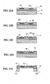
- FIGS. 12A through 12E show part (left half) of a section in the X-axis direction (II-II section) in FIG. 1 to explain a main process.
- an SOI wafer is a Si single crystal substrate constructed with a Si base substrate 60, an SOI layer 80 on the top surface, which is a Si active layer, and a SiO 2 layer 70, which is between the Si base substrate 60 and the SOI layer 80, and is used as an etching stopper, as denoted by reference numerals in FIG. 12A.
- the base substrate 60 has thickness of 625 ⁇ m
- SiO 2 layer has thickness of 1 ⁇ m
- the SOI layer has thickness of about 10 ⁇ m.
- the first step of the production process is to make a pattern of a predetermined form with a photoresist or thermally oxidized SiO 2 film or the like on the surface of the SOI layer 80 and to make piezoresistors 161 and 162 with boron being diffused by an impurity diffusion process such as ion implantation (FIG. 12A).
- an impurity diffusion process such as ion implantation (FIG. 12A).
- surface impurity density about 2 ⁇ 10 18 atoms/cm 3 is adopted, from the viewpoint of both the temperature characteristics and sensitivity.
- a protection film 41 is produced (FIG. 12B).
- the protection film 41 a multilayer film of SiO 2 and PSG (Phosphorous silicated glass) that are generally used in a semiconductor technology are used to have a gettering effect of movable ion.
- a two-layer film of SiO 2 and SiN may be used. It is preferable that the thickness of the protection film 41 is made as thin as possible to decrease stress in terms of high sensitivity, and therefore it is made 0.3 ⁇ m to 0.5 ⁇ m.
- through-holes 40a for connecting electrodes are formed in the protection film 41 on both ends of the piezoresistors 161 and 162 by a wet etching with hydrofluoric acid as a predominant ingredient (FIG. 12C).
- a film of aluminum alloy (aluminum, copper, silicon and the like are main ingredients) is formed by spattering. The thickness is 0.3 ⁇ m to 0.5 ⁇ m.
- Lead electrodes 40 are formed by photo etching (FIG. 12D).
- the SOI layer 80 is etched by a dry etching method or the like to form a through-hole pattern 150 to the thin portion shown in FIG. 1.
- a photoresist mask is formed in the shapes of the mass portion 120 and the frame 110 with the positions of the piezoresistors 161 and 162 on the surface, the through-hole pattern 150 to the SOI layer 80 and the like are aligned with use of a double-side aligner device, the base substrate 60 is etched by the dry etching method, and the SiO 2 layer 70 as the etching stopper is removed by wet etching (FIG. 12E).
- the dry etching step an etching process mainly using SF 6 -gas and a process adhering polymer mainly containing C 4 F 8 -gas on the side walls and the inside walls are repeated alternately.
- etching solution to etch the SiO 2 layer buffered hydrofluoric acid is used.
- the elastic support arms 131, 132, 133 and 134 are formed in the dry etching process, in some cases it is preferable to leave the SiO 2 layer 70 as the etching stopper without removing it in order to keep balance of the entire stress, forming a lamination of the SiO 2 layer and the silicon layer as the elastic support arms, and part of the SiO 2 layer 70 may be left as the etching stopper on the back side of the elastic support arms.
- acceleration sensor elements formed on the wafer are cut into sensor chips one by one with use of a dicer or the like, and via the assembly process such as packaging and the like, the semiconductor acceleration sensor 100 is completed.
- the difference between the Z-axis output and the X-axis (or the Y-axis) output can be improved to be 35% or less, preferably, 20% or less.
- the resistance values and thermal properties of the strain gauges are the same, and therefore it is not necessary to prepare an amplifier for each axis, thus making it possible to provide a compact and less expensive semiconductor type triaxial acceleration sensor.
Landscapes
- Physics & Mathematics (AREA)
- General Physics & Mathematics (AREA)
- Pressure Sensors (AREA)
- Force Measurement Appropriate To Specific Purposes (AREA)
Applications Claiming Priority (4)
| Application Number | Priority Date | Filing Date | Title |
|---|---|---|---|
| JP2002083161A JP3642054B2 (ja) | 2002-03-25 | 2002-03-25 | ピエゾ抵抗型3軸加速度センサ |
| JP2002083161 | 2002-03-25 | ||
| JP2002103364A JP2003294781A (ja) | 2002-04-05 | 2002-04-05 | ピエゾ抵抗型3軸加速度センサ |
| JP2002103364 | 2002-04-05 |
Publications (2)
| Publication Number | Publication Date |
|---|---|
| EP1348967A2 true EP1348967A2 (fr) | 2003-10-01 |
| EP1348967A3 EP1348967A3 (fr) | 2005-02-02 |
Family
ID=27807005
Family Applications (1)
| Application Number | Title | Priority Date | Filing Date |
|---|---|---|---|
| EP03006231A Withdrawn EP1348967A3 (fr) | 2002-03-25 | 2003-03-20 | Capteur d'accélération |
Country Status (4)
| Country | Link |
|---|---|
| US (1) | US6763719B2 (fr) |
| EP (1) | EP1348967A3 (fr) |
| KR (1) | KR100508198B1 (fr) |
| CN (1) | CN100334453C (fr) |
Cited By (1)
| Publication number | Priority date | Publication date | Assignee | Title |
|---|---|---|---|---|
| DK178437B1 (en) * | 2011-02-07 | 2016-02-29 | Ion Geophysical Corp | METHOD AND DEVICE FOR REGISTRATION OF UNDERWATER SIGNALS |
Families Citing this family (13)
| Publication number | Priority date | Publication date | Assignee | Title |
|---|---|---|---|---|
| KR100824926B1 (ko) * | 2003-12-24 | 2008-04-28 | 히타치 긴조쿠 가부시키가이샤 | 반도체형 3축 가속도 센서 |
| JP2006177823A (ja) * | 2004-12-22 | 2006-07-06 | Oki Electric Ind Co Ltd | 加速度センサ |
| JP2006201041A (ja) * | 2005-01-20 | 2006-08-03 | Oki Electric Ind Co Ltd | 加速度センサ |
| US7231828B2 (en) * | 2005-09-23 | 2007-06-19 | Kulite Semiconductor Products, Inc. | High temperature pressure sensing system |
| KR101001775B1 (ko) * | 2006-06-08 | 2010-12-15 | 가부시키가이샤 무라타 세이사쿠쇼 | 가속도 센서 |
| US20090223292A1 (en) * | 2006-09-28 | 2009-09-10 | Hitachi Metals, Ltd. | Acceleration sensor |
| US7594440B2 (en) * | 2006-10-05 | 2009-09-29 | Endevco Corporation | Highly sensitive piezoresistive element |
| JP2009053180A (ja) | 2007-07-27 | 2009-03-12 | Hitachi Metals Ltd | 加速度センサー |
| KR101299729B1 (ko) * | 2012-05-29 | 2013-08-22 | 삼성전기주식회사 | 센서 |
| KR101367047B1 (ko) * | 2012-11-23 | 2014-02-24 | 삼성전기주식회사 | 가속도 센서 |
| DE102013212118B4 (de) * | 2013-06-25 | 2025-06-26 | Robert Bosch Gmbh | Sensorsystem mit zwei Inertialsensoren |
| TW201728905A (zh) * | 2016-02-03 | 2017-08-16 | 智動全球股份有限公司 | 加速度計 |
| CN112093771A (zh) * | 2019-06-17 | 2020-12-18 | 芜湖天波光电技术研究院有限公司 | 一种单轴高冲击加速度传感器及其制造方法 |
Family Cites Families (9)
| Publication number | Priority date | Publication date | Assignee | Title |
|---|---|---|---|---|
| JPS63169078A (ja) | 1987-01-06 | 1988-07-13 | Nippon Denso Co Ltd | 半導体振動・加速度センサ |
| EP0461265B1 (fr) * | 1989-12-28 | 1995-05-10 | Wacoh Corporation | Capteurs d'accélération |
| JPH04339266A (ja) * | 1991-02-08 | 1992-11-26 | Tokai Rika Co Ltd | 加速度センサおよびその製造方法 |
| DE4340664C2 (de) * | 1993-11-30 | 1999-02-11 | Helmut Dipl Ing Dr Crazzolara | Piezoresistiver Beschleunigungsaufnehmer |
| JPH08211091A (ja) * | 1995-02-07 | 1996-08-20 | Mitsubishi Electric Corp | 半導体加速度検出装置 |
| JPH08285883A (ja) * | 1995-04-14 | 1996-11-01 | Matsushita Electric Works Ltd | 加速度センサ |
| JPH0945935A (ja) * | 1995-07-26 | 1997-02-14 | Akebono Brake Ind Co Ltd | 加速度センサー及びその製造方法 |
| US6293149B1 (en) * | 1997-02-21 | 2001-09-25 | Matsushita Electric Works, Ltd. | Acceleration sensor element and method of its manufacture |
| JP2003232803A (ja) * | 2002-02-12 | 2003-08-22 | Hitachi Metals Ltd | 半導体型加速度センサ |
-
2003
- 2003-03-11 US US10/384,645 patent/US6763719B2/en not_active Expired - Lifetime
- 2003-03-20 EP EP03006231A patent/EP1348967A3/fr not_active Withdrawn
- 2003-03-25 KR KR10-2003-0018405A patent/KR100508198B1/ko not_active Expired - Fee Related
- 2003-03-25 CN CNB031082149A patent/CN100334453C/zh not_active Expired - Fee Related
Non-Patent Citations (1)
| Title |
|---|
| None |
Cited By (3)
| Publication number | Priority date | Publication date | Assignee | Title |
|---|---|---|---|---|
| DK178437B1 (en) * | 2011-02-07 | 2016-02-29 | Ion Geophysical Corp | METHOD AND DEVICE FOR REGISTRATION OF UNDERWATER SIGNALS |
| US9294011B2 (en) | 2011-02-07 | 2016-03-22 | Ion Geophysical Corporation | Method and apparatus for sensing underwater signals |
| US9502993B2 (en) | 2011-02-07 | 2016-11-22 | Ion Geophysical Corporation | Method and apparatus for sensing signals |
Also Published As
| Publication number | Publication date |
|---|---|
| US6763719B2 (en) | 2004-07-20 |
| KR100508198B1 (ko) | 2005-08-17 |
| EP1348967A3 (fr) | 2005-02-02 |
| US20030177832A1 (en) | 2003-09-25 |
| KR20030077424A (ko) | 2003-10-01 |
| CN1447120A (zh) | 2003-10-08 |
| CN100334453C (zh) | 2007-08-29 |
Similar Documents
| Publication | Publication Date | Title |
|---|---|---|
| US4553436A (en) | Silicon accelerometer | |
| KR100715644B1 (ko) | 가속도 센서 | |
| US6662659B2 (en) | Acceleration sensor | |
| US10775248B2 (en) | MEMS strain gauge sensor and manufacturing method | |
| CN100565211C (zh) | 半导体型三轴加速度传感器 | |
| Diem et al. | SOI'SIMOX'; from bulk to surface micromachining, a new age for silicon sensors and actuators | |
| US20040025591A1 (en) | Accleration sensor | |
| US5239870A (en) | Semiconductor acceleration sensor with reduced cross axial sensitivity | |
| US6763719B2 (en) | Acceleration sensor | |
| JPH1151967A (ja) | 多軸加速度センサ及びその製造方法 | |
| JPH10177033A (ja) | 加速度測定装置 | |
| EP1298442A1 (fr) | Capteur d'accélération | |
| EP1517151B1 (fr) | Capteur d'accélération | |
| JP4335545B2 (ja) | 圧力と加速度との双方を検出するセンサおよびその製造方法 | |
| JP2004177357A (ja) | 半導体加速度センサ | |
| CN100422697C (zh) | 加速度传感器 | |
| JP3985215B2 (ja) | 半導体加速度センサー | |
| JP2006098323A (ja) | 半導体型3軸加速度センサ | |
| JPH05281251A (ja) | 加速度センサおよびその製造方法 | |
| JPH1144705A (ja) | 半導体加速度センサおよびその製造方法 | |
| JPH0337534A (ja) | 半導体歪検出装置 | |
| JP3187754B2 (ja) | 半導体センサおよびその製造方法 | |
| JPH08160066A (ja) | 加速度センサ | |
| JPH04192370A (ja) | 半導体加速度センサ |
Legal Events
| Date | Code | Title | Description |
|---|---|---|---|
| PUAI | Public reference made under article 153(3) epc to a published international application that has entered the european phase |
Free format text: ORIGINAL CODE: 0009012 |
|
| AK | Designated contracting states |
Kind code of ref document: A2 Designated state(s): AT BE BG CH CY CZ DE DK EE ES FI FR GB GR HU IE IT LI LU MC NL PT RO SE SI SK TR |
|
| AX | Request for extension of the european patent |
Extension state: AL LT LV MK |
|
| PUAL | Search report despatched |
Free format text: ORIGINAL CODE: 0009013 |
|
| AK | Designated contracting states |
Kind code of ref document: A3 Designated state(s): AT BE BG CH CY CZ DE DK EE ES FI FR GB GR HU IE IT LI LU MC NL PT RO SE SI SK TR |
|
| AX | Request for extension of the european patent |
Extension state: AL LT LV MK |
|
| 17P | Request for examination filed |
Effective date: 20050322 |
|
| AKX | Designation fees paid |
Designated state(s): DE FI |
|
| 17Q | First examination report despatched |
Effective date: 20100913 |
|
| STAA | Information on the status of an ep patent application or granted ep patent |
Free format text: STATUS: THE APPLICATION IS DEEMED TO BE WITHDRAWN |
|
| 18D | Application deemed to be withdrawn |
Effective date: 20121002 |