EP1353042B1 - Méthode pour modifier une installation de turbine à gaz simple, méthode pour réutiliser un catalyseur et un catalyseur reproduit - Google Patents
Méthode pour modifier une installation de turbine à gaz simple, méthode pour réutiliser un catalyseur et un catalyseur reproduit Download PDFInfo
- Publication number
- EP1353042B1 EP1353042B1 EP03006094A EP03006094A EP1353042B1 EP 1353042 B1 EP1353042 B1 EP 1353042B1 EP 03006094 A EP03006094 A EP 03006094A EP 03006094 A EP03006094 A EP 03006094A EP 1353042 B1 EP1353042 B1 EP 1353042B1
- Authority
- EP
- European Patent Office
- Prior art keywords
- catalyst
- denitration catalyst
- temperature denitration
- high temperature
- produced
- Prior art date
- Legal status (The legal status is an assumption and is not a legal conclusion. Google has not performed a legal analysis and makes no representation as to the accuracy of the status listed.)
- Expired - Lifetime
Links
- 239000003054 catalyst Substances 0.000 title claims description 104
- 238000000034 method Methods 0.000 title claims description 27
- GWEVSGVZZGPLCZ-UHFFFAOYSA-N Titan oxide Chemical compound O=[Ti]=O GWEVSGVZZGPLCZ-UHFFFAOYSA-N 0.000 claims description 19
- JKQOBWVOAYFWKG-UHFFFAOYSA-N molybdenum trioxide Chemical compound O=[Mo](=O)=O JKQOBWVOAYFWKG-UHFFFAOYSA-N 0.000 claims description 16
- XLYOFNOQVPJJNP-UHFFFAOYSA-N water Substances O XLYOFNOQVPJJNP-UHFFFAOYSA-N 0.000 claims description 12
- 238000007654 immersion Methods 0.000 claims description 11
- 238000001035 drying Methods 0.000 claims description 4
- 239000007789 gas Substances 0.000 description 57
- 238000010276 construction Methods 0.000 description 11
- MUBZPKHOEPUJKR-UHFFFAOYSA-N Oxalic acid Chemical compound OC(=O)C(O)=O MUBZPKHOEPUJKR-UHFFFAOYSA-N 0.000 description 10
- 238000012986 modification Methods 0.000 description 9
- 230000004048 modification Effects 0.000 description 9
- 239000000203 mixture Substances 0.000 description 5
- 238000011084 recovery Methods 0.000 description 4
- QGZKDVFQNNGYKY-UHFFFAOYSA-N Ammonia Chemical compound N QGZKDVFQNNGYKY-UHFFFAOYSA-N 0.000 description 3
- 239000007788 liquid Substances 0.000 description 3
- 235000006408 oxalic acid Nutrition 0.000 description 3
- 238000011144 upstream manufacturing Methods 0.000 description 3
- 239000002918 waste heat Substances 0.000 description 3
- IJGRMHOSHXDMSA-UHFFFAOYSA-N Atomic nitrogen Chemical compound N#N IJGRMHOSHXDMSA-UHFFFAOYSA-N 0.000 description 2
- 238000006243 chemical reaction Methods 0.000 description 2
- 239000002699 waste material Substances 0.000 description 2
- QGZKDVFQNNGYKY-UHFFFAOYSA-O Ammonium Chemical compound [NH4+] QGZKDVFQNNGYKY-UHFFFAOYSA-O 0.000 description 1
- YASYEJJMZJALEJ-UHFFFAOYSA-N Citric acid monohydrate Chemical compound O.OC(=O)CC(O)(C(O)=O)CC(O)=O YASYEJJMZJALEJ-UHFFFAOYSA-N 0.000 description 1
- XHCLAFWTIXFWPH-UHFFFAOYSA-N [O-2].[O-2].[O-2].[O-2].[O-2].[V+5].[V+5] Chemical compound [O-2].[O-2].[O-2].[O-2].[O-2].[V+5].[V+5] XHCLAFWTIXFWPH-UHFFFAOYSA-N 0.000 description 1
- 229910021529 ammonia Inorganic materials 0.000 description 1
- 238000002485 combustion reaction Methods 0.000 description 1
- 230000000694 effects Effects 0.000 description 1
- 238000005516 engineering process Methods 0.000 description 1
- 230000002708 enhancing effect Effects 0.000 description 1
- 239000000446 fuel Substances 0.000 description 1
- XDBSEZHMWGHVIL-UHFFFAOYSA-M hydroxy(dioxo)vanadium Chemical compound O[V](=O)=O XDBSEZHMWGHVIL-UHFFFAOYSA-M 0.000 description 1
- 238000009434 installation Methods 0.000 description 1
- 230000007774 longterm Effects 0.000 description 1
- 238000005259 measurement Methods 0.000 description 1
- LFETXMWECUPHJA-UHFFFAOYSA-N methanamine;hydrate Chemical compound O.NC LFETXMWECUPHJA-UHFFFAOYSA-N 0.000 description 1
- 229910000476 molybdenum oxide Inorganic materials 0.000 description 1
- LNOPIUAQISRISI-UHFFFAOYSA-N n'-hydroxy-2-propan-2-ylsulfonylethanimidamide Chemical compound CC(C)S(=O)(=O)CC(N)=NO LNOPIUAQISRISI-UHFFFAOYSA-N 0.000 description 1
- 229910052757 nitrogen Inorganic materials 0.000 description 1
- 229910000069 nitrogen hydride Inorganic materials 0.000 description 1
- QGLKJKCYBOYXKC-UHFFFAOYSA-N nonaoxidotritungsten Chemical compound O=[W]1(=O)O[W](=O)(=O)O[W](=O)(=O)O1 QGLKJKCYBOYXKC-UHFFFAOYSA-N 0.000 description 1
- PQQKPALAQIIWST-UHFFFAOYSA-N oxomolybdenum Chemical compound [Mo]=O PQQKPALAQIIWST-UHFFFAOYSA-N 0.000 description 1
- 239000000843 powder Substances 0.000 description 1
- OGIDPMRJRNCKJF-UHFFFAOYSA-N titanium oxide Inorganic materials [Ti]=O OGIDPMRJRNCKJF-UHFFFAOYSA-N 0.000 description 1
- 229910001930 tungsten oxide Inorganic materials 0.000 description 1
- 229910052720 vanadium Inorganic materials 0.000 description 1
- LEONUFNNVUYDNQ-UHFFFAOYSA-N vanadium atom Chemical compound [V] LEONUFNNVUYDNQ-UHFFFAOYSA-N 0.000 description 1
- 229910001935 vanadium oxide Inorganic materials 0.000 description 1
Images

Classifications
-
- B—PERFORMING OPERATIONS; TRANSPORTING
- B01—PHYSICAL OR CHEMICAL PROCESSES OR APPARATUS IN GENERAL
- B01J—CHEMICAL OR PHYSICAL PROCESSES, e.g. CATALYSIS OR COLLOID CHEMISTRY; THEIR RELEVANT APPARATUS
- B01J23/00—Catalysts comprising metals or metal oxides or hydroxides, not provided for in group B01J21/00
- B01J23/90—Regeneration or reactivation
- B01J23/92—Regeneration or reactivation of catalysts comprising metals, oxides or hydroxides provided for in groups B01J23/02 - B01J23/36
-
- B—PERFORMING OPERATIONS; TRANSPORTING
- B01—PHYSICAL OR CHEMICAL PROCESSES OR APPARATUS IN GENERAL
- B01D—SEPARATION
- B01D53/00—Separation of gases or vapours; Recovering vapours of volatile solvents from gases; Chemical or biological purification of waste gases, e.g. engine exhaust gases, smoke, fumes, flue gases, aerosols
- B01D53/34—Chemical or biological purification of waste gases
- B01D53/74—General processes for purification of waste gases; Apparatus or devices specially adapted therefor
- B01D53/86—Catalytic processes
- B01D53/8621—Removing nitrogen compounds
- B01D53/8625—Nitrogen oxides
- B01D53/8628—Processes characterised by a specific catalyst
-
- B—PERFORMING OPERATIONS; TRANSPORTING
- B01—PHYSICAL OR CHEMICAL PROCESSES OR APPARATUS IN GENERAL
- B01D—SEPARATION
- B01D53/00—Separation of gases or vapours; Recovering vapours of volatile solvents from gases; Chemical or biological purification of waste gases, e.g. engine exhaust gases, smoke, fumes, flue gases, aerosols
- B01D53/34—Chemical or biological purification of waste gases
- B01D53/96—Regeneration, reactivation or recycling of reactants
-
- B—PERFORMING OPERATIONS; TRANSPORTING
- B01—PHYSICAL OR CHEMICAL PROCESSES OR APPARATUS IN GENERAL
- B01J—CHEMICAL OR PHYSICAL PROCESSES, e.g. CATALYSIS OR COLLOID CHEMISTRY; THEIR RELEVANT APPARATUS
- B01J38/00—Regeneration or reactivation of catalysts, in general
- B01J38/48—Liquid treating or treating in liquid phase, e.g. dissolved or suspended
- B01J38/485—Impregnating or reimpregnating with, or deposition of metal compounds or catalytically active elements
-
- F—MECHANICAL ENGINEERING; LIGHTING; HEATING; WEAPONS; BLASTING
- F01—MACHINES OR ENGINES IN GENERAL; ENGINE PLANTS IN GENERAL; STEAM ENGINES
- F01K—STEAM ENGINE PLANTS; STEAM ACCUMULATORS; ENGINE PLANTS NOT OTHERWISE PROVIDED FOR; ENGINES USING SPECIAL WORKING FLUIDS OR CYCLES
- F01K23/00—Plants characterised by more than one engine delivering power external to the plant, the engines being driven by different fluids
- F01K23/02—Plants characterised by more than one engine delivering power external to the plant, the engines being driven by different fluids the engine cycles being thermally coupled
- F01K23/06—Plants characterised by more than one engine delivering power external to the plant, the engines being driven by different fluids the engine cycles being thermally coupled combustion heat from one cycle heating the fluid in another cycle
- F01K23/10—Plants characterised by more than one engine delivering power external to the plant, the engines being driven by different fluids the engine cycles being thermally coupled combustion heat from one cycle heating the fluid in another cycle with exhaust fluid of one cycle heating the fluid in another cycle
-
- Y—GENERAL TAGGING OF NEW TECHNOLOGICAL DEVELOPMENTS; GENERAL TAGGING OF CROSS-SECTIONAL TECHNOLOGIES SPANNING OVER SEVERAL SECTIONS OF THE IPC; TECHNICAL SUBJECTS COVERED BY FORMER USPC CROSS-REFERENCE ART COLLECTIONS [XRACs] AND DIGESTS
- Y02—TECHNOLOGIES OR APPLICATIONS FOR MITIGATION OR ADAPTATION AGAINST CLIMATE CHANGE
- Y02E—REDUCTION OF GREENHOUSE GAS [GHG] EMISSIONS, RELATED TO ENERGY GENERATION, TRANSMISSION OR DISTRIBUTION
- Y02E20/00—Combustion technologies with mitigation potential
- Y02E20/16—Combined cycle power plant [CCPP], or combined cycle gas turbine [CCGT]
Definitions
- the present invention relates to a method for modifying a gas turbine single plant into a combined cycle plant comprising a combination of this gas turbine, a waste heat recovery boiler and a steam turbine and a method for re-using a used high temperature denitration catalyst of the gas turbine single plant as an intermediate temperature denitration catalyst of other modified, existing or new plants and also relates to a re-produced catalyst.
- gas turbine single plants that are excellent in the operability and constructible with less investment cost and shorter period
- the gas turbine single plant is less excellent in the long term plant efficiency and hence it is effective that a gas turbine single plant is first constructed to be modified in the future by re-powering work into a combined cycle plant that is excellent in the plant efficiency.
- a catalyst that contains TiO 2 (titanium oxide) as a main component and includes at least one of WO 3 (tungsten oxide) and MoO 3 (molybdenum oxide) and further includes V 2 O 5 (vanadium oxide).
- the denitration catalyst containing the minute amount or none of V 2 O 5 component is a catalyst that is optimized for the high temperature.
- this high temperature denitration catalyst cannot be used for the combined cycle plant in which the temperature of the exhaust gas to be denitrified is an intermediate temperature of 200 to 450°C.
- Patent Document 1
- Patent Document 2
- Patent Document 3
- Patent Document 4
- the present invention provides a method for modifying a gas turbine single plant into a combined cycle plant by which, in modifying the gas turbine single plant into a combined cycle plant, a used high temperature denitration catalyst is reproduced as an intermediate temperature denitration catalyst and this re-produced intermediate temperature denitration catalyst is re-used as a denitration catalyst of the combined cycle plant after modified.
- the used high temperature denitration catalyst of the gas turbine single plant is re-produced as the intermediate temperature denitration catalyst to be used for the combined cycle plant.
- the equipment cost required for the re-powering of the plant can be largely reduced.
- the used high temperature denitration catalyst is re-used, the waste cost thereof is saved and thereby a burden on the environment caused by the waste can be alleviated.
- the present invention provides a method for re-using a used high temperature denitration catalyst by which the used high temperature denitration catalyst of a gas turbine single plant is re-produced as an intermediate temperature denitration catalyst and this re-produced intermediate temperature denitration catalyst is re-used as an intermediate temperature denitration catalyst of other modified, existing or new plants.
- the used high temperature denitration catalyst in re-powering the gas turbine single plant, can be effectively re-used as an intermediate temperature denitration catalyst and thereby a re-selling business of the catalyst as an intermediate temperature denitration catalyst of modified, existing or new plants other than the mentioned gas turbine single plant can be appropriately realized corresponding to a required amount of the catalyst, a geographical position of the plant or the like.
- TiO 2 is contained as a main component and at least one of WO 3 and MoO 3 is included.
- the composition may include V 2 O 5 of 0.5 wt(weight)% or less, preferably 0.2 wt% or less, or may include none of V 2 O 5 .
- the used high temperature denitration catalyst is of the abovementioned composition, the quantity of the catalyst available for re-use is large and thus the modifying or re-using method of the present invention is extremely effective.
- the present invention provides a modifying or re-using method in which the intermediate temperature denitration catalyst is re-produced by including V 2 O 5 component of 0.5 wt% or more, preferably 1.0 wt% or more, in the used high temperature denitration catalyst as well as provides a re-produced catalyst that is re-produced with the same composition included in the used high temperature denitration catalyst.
- the present invention provides a modifying and re-using method in which, where the high temperature denitration catalyst to be re-used is a catalyst that is optimized so as to be used in the temperature range up to maximum 450 to 600°C, the intermediate temperature denitration catalyst is re-produced by including V (vanadium) component in the used high temperature denitration catalyst and is optimized so as to be used in the temperature range of 200 to 450°C as well as the present invention provides a re-produced catalyst that is optimized for the same temperature range.
- V vanadium
- the present invention provides a modifying or re-using method in which the inclusion treatment of the V component is carried out by immersion into V-containing water solution and drying and/or burning as well as it provides a re-produced catalyst that is re-produced by the same treatment.
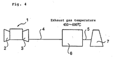
- Fig. 4 shows a gas turbine single plant in the prior art before it is modified into a combined cycle plant by applying the present invention.
- numeral 1 designates a gas turbine equipment
- numeral 2 designates a compressor
- numeral 3 designates a gas turbine.
- the construction is made such that exhaust gas of the gas turbine 3 flows through a duct 4 to be led into a denitration equipment 6 for denitration treatment therein and then further flows through a duct 5 to be emitted into the air from a stack 7.
- Temperature of the exhaust gas coming from the gas turbine 3 to be led into the denitration equipment 6 is as high as 450 to 600°C.
- a high temperature denitration catalyst is used so as to stand such a high temperature for effecting the denitration reaction.
- the denitration catalyst contains TiO 2 as a main component and an active component, such as WO 3 or MoO 3 , as the gas to be treated is of the high temperature as mentioned above, inclusion of V component in the catalyst is very small or even zero such that V 2 O 5 that is thermally vulnerable is 0.5 wt% or less, preferably 0.2 wt% or less, or no V 2 O 5 is included.
- the exhaust gas to be treated for denitration is first injected with NH 3 (ammonia) so as to be made contact with the catalyst, and by the reactions that 4NO + 4NH 3 + O 2 ⁇ 4N 2 + 6H 2 O, NO + NO 2 + 2NH 3 ⁇ 2N 2 + 3H 2 O, NO and NO 2 are decomposed into an innoxious nitrogen and water.
- NH 3 ammonia
- Fig. 1 shows a combined cycle plant modified by applying the present invention.
- numeral 9 designates an exhaust gas boiler, that uses the exhaust gas of the gas turbine equipment 1 as a heat source.
- Numeral 10 designates a steam turbine, that is operated by being supplied with steam generated at the exhaust gas boiler 9.
- temperature of the exhaust gas coming out of the exhaust gas boiler 9 is reduced to an intermediate temperature of 450 to 200°C.
- This intermediate temperature exhaust gas is applied with the denitration treatment at the denitration equipment 8 and is then emitted into the air from the stack 7.
- the intermediate temperature denitration catalyst obtained by the present invention is used.
- the intermediate temperature denitration catalyst to be used in the denitration equipment 8 is re-produced from the high temperature denitration catalyst that has been used in the denitration equipment 6 of the gas turbine single plant shown in Fig. 4.
- the high temperature denitration catalyst used in the denitration equipment 6 of Fig. 4 contains TiO 2 as a main component and an active component of WO 3 or MoO 3 or the like, but inclusion of the V component that is thermally vulnerable is very small or even zero.
- the used high temperature denitration catalyst is treated so as to contain V 2 O 5 of 0.5 wt% or more, preferably 1.0 wt% or more.
- the catalyst For treating the TiO 2 •WO 3 group high temperature denitration catalyst so as to contain V 2 O 5 , the catalyst is first immersed in an oxalic acid solution of V 2 O 5 and is then dried and/or burned. If drying only is applied, the catalyst is changed to a burned state by the exhaust gas in the actual operation.
- W1 is weight of the catalyst before immersion (kg) and W2 is weight of the catalyst after immersion (kg).
- B is the aimed V 2 O 5 concentration in the catalyst and a is the water content (liter/kg).
- Oxalic acid (H 2 C 2 O 4 ) of 2.5 Xkg is dissolved in warm water of about 0.9 liter.
- V 2 O 5 powder Xkg is gradually added into this solution to be dissolved therein and then water is added so that a solution for immersion of 1 liter is made.
- the used high temperature denitration catalyst is immersed into this immersion solution for about 1 minute. Then, this catalyst is dried and burned for 3 hours at 550°C.
- the high temperature denitration catalyst to be re-used is not necessarily a TiO 2 •WO 3 group catalyst.
- composition ratio of the high temperature denitration catalyst has been taken from a basic framework that TiO 2 is 60 to 80 wt%, WO 3 (MoO 3 ) is 5 to 25 wt% and V 2 O 5 is 0 to 10 wt%, wherein MoO 3 is the alternative for W03, the composition ratio may be optimized according to fuel for combustion, temperature of the gas to be treated, etc.
- the procedure of treatment to give V component to the catalyst is not limited to the use of the oxalic acid solution but, for example, citric acid water solution, methylamine water solution of ammonium metavanadic acid, sulfamic acid water solution, etc. may be used as wash medium.
- the construction shown in Fig. 2 in which the denitration equipment 8 is interposed between an exhaust gas boiler 9-1 and an exhaust gas boiler 9-2 is made such that, in the gas turbine single plant, spaces are left beforehand upstream and downstream of the denitration equipment 8 and the two exhaust gas boilers 9-1, 9-2 are added on both sides of the denitration equipment 8 later in the modification to the combined cycle plant.
- the cost for modification to the combined cycle plant becomes higher than the construction shown in Fig. 1, a larger waste heat recovery can be realized and a further enhanced efficiency can be expected in the plant operation.
- the construction shown in Fig. 3 in which the denitration equipment 8 is assembled into the exhaust gas boiler 9 is made such that the denitration equipment 8 is structured beforehand so as to be assembled into the exhaust gas boiler and the denitration equipment 8 is so assembled later in the modification to the combined cycle plant.
- the equipment structure and the modification work become somewhat complicated, the high efficiency in the plant operation is expected similarly to the construction shown in Fig. 2, the installation space is reduced and a compact sized plant can be realized.
Landscapes
- Chemical & Material Sciences (AREA)
- Engineering & Computer Science (AREA)
- Chemical Kinetics & Catalysis (AREA)
- Environmental & Geological Engineering (AREA)
- Combustion & Propulsion (AREA)
- Oil, Petroleum & Natural Gas (AREA)
- Materials Engineering (AREA)
- Organic Chemistry (AREA)
- General Chemical & Material Sciences (AREA)
- Analytical Chemistry (AREA)
- Health & Medical Sciences (AREA)
- Biomedical Technology (AREA)
- General Engineering & Computer Science (AREA)
- Sustainable Development (AREA)
- Life Sciences & Earth Sciences (AREA)
- Mechanical Engineering (AREA)
- Catalysts (AREA)
- Exhaust Gas Treatment By Means Of Catalyst (AREA)
- Engine Equipment That Uses Special Cycles (AREA)
Claims (9)
- Procédé pour modifier une installation de turbine à gaz simple en une installation à cycle combiné, caractérisé en ce qu'il comprend les étapes consistant à transformer un catalyseur de dénitration à haute température usé de ladite installation de turbine à gaz simple en un catalyseur de dénitration à température intermédiaire et à réutiliser ledit catalyseur de dénitration à température intermédiaire ainsi transformé en tant que catalyseur de dénitration de ladite installation à cycle combiné après l'avoir modifiée.
- Procédé pour réutiliser un catalyseur de dénitration à haute température usé, caractérisé en ce qu'il comprend les étapes consistant à transformer ledit catalyseur de dénitration à haute température usé d'une installation de turbine à gaz simple en un catalyseur de dénitration à température intermédiaire et à réutiliser ledit catalyseur de dénitration à température intermédiaire ainsi transformé en tant que catalyseur de dénitration à température intermédiaire d'autres installations modifiées, existantes ou nouvelles.
- Procédé de modification ou de réutilisation selon la revendication 1 ou 2, caractérisé en ce que ledit catalyseur de dénitration à haute température contient TiO2 en tant que constituant principal et au moins l'un parmi WO3 et MoO3 et comprend en outre V2O5 à 0,5 % en poids ou moins, de préférence 0,2 % en poids ou moins, ou pas de V2O5.
- Procédé de modification ou de réutilisation selon la revendication 1 ou 2, caractérisé en ce que ledit catalyseur de dénitration à température intermédiaire est transformé en incluant le constituant V2O5 à 0,5 % en poids ou plus, de préférence 1,0 % en poids ou plus, dans ledit catalyseur de dénitration à haute température usé.
- Procédé de modification ou de réutilisation selon la revendication 1 ou 2, caractérisé en ce que ledit catalyseur de dénitration à haute température est un catalyseur qui est optimisé de façon à être utilisé dans la gamme de température jusqu'à 450 à 600 °C maximum et ledit catalyseur de dénitration à température intermédiaire, qui est transformé en incluant le constituant V dans ledit catalyseur de dénitration à haute température usé, est optimisé de façon à être utilisé dans la gamme de température de 200 à 450 °C.
- Procédé de modification ou de réutilisation selon la revendication 5, caractérisé en ce que le traitement d'inclusion dudit constituant V est effectué par immersion dans une solution d'eau contenant V et séchage et/ou combustion.
- Catalyseur transformé, caractérisé en ce qu'il est transformé en un catalyseur de dénitration à température intermédiaire en incluant le constituant V2O5 à 0,5 % en poids ou plus, de préférence 1,0 % en poids ou plus, dans un catalyseur de dénitration à haute température usé qui contient TiO2 en tant que principal constituant et au moins l'un parmi WO3 et MoO3 et comprend en outre V2O5 à 0,5 % en poids ou moins, de préférence 0,2 % en poids ou moins, ou pas de V2O5.
- Catalyseur transformé selon la revendication 7, caractérisé en ce que ledit catalyseur de dénitration à haute température est un catalyseur qui est optimisé de façon à être utilisé dans la gamme de température jusqu'à 450 à 600°C maximum et ledit catalyseur de dénitration à température intermédiaire qui est transformé en incluant le constituant V dans ledit catalyseur de dénitration à haute température usé est optimisé de façon à être utilisé dans la gamme de température de 200 à 450 °C.
- Catalyseur transformé selon la revendication 8, caractérisé en ce que le traitement d'inclusion dudit constituant V est effectué par immersion dans une solution d'eau contenant V et séchage et/ou combustion.
Applications Claiming Priority (4)
| Application Number | Priority Date | Filing Date | Title |
|---|---|---|---|
| JP2002107720 | 2002-04-10 | ||
| JP2002107720 | 2002-04-10 | ||
| JP2002296071A JP4167039B2 (ja) | 2002-04-10 | 2002-10-09 | ガスタービン単独プラントの改造方法、触媒の再利用方法 |
| JP2002296071 | 2002-10-09 |
Publications (3)
| Publication Number | Publication Date |
|---|---|
| EP1353042A2 EP1353042A2 (fr) | 2003-10-15 |
| EP1353042A3 EP1353042A3 (fr) | 2004-06-16 |
| EP1353042B1 true EP1353042B1 (fr) | 2006-07-12 |
Family
ID=26625718
Family Applications (1)
| Application Number | Title | Priority Date | Filing Date |
|---|---|---|---|
| EP03006094A Expired - Lifetime EP1353042B1 (fr) | 2002-04-10 | 2003-03-19 | Méthode pour modifier une installation de turbine à gaz simple, méthode pour réutiliser un catalyseur et un catalyseur reproduit |
Country Status (8)
| Country | Link |
|---|---|
| US (1) | US7316988B2 (fr) |
| EP (1) | EP1353042B1 (fr) |
| JP (1) | JP4167039B2 (fr) |
| CA (1) | CA2424417C (fr) |
| DE (1) | DE60306707T2 (fr) |
| DK (1) | DK1353042T3 (fr) |
| ES (1) | ES2268191T3 (fr) |
| NO (1) | NO324842B1 (fr) |
Families Citing this family (14)
| Publication number | Priority date | Publication date | Assignee | Title |
|---|---|---|---|---|
| WO2011140519A2 (fr) | 2010-05-07 | 2011-11-10 | Medicus Biosciences, Llc | Préformulation pharmaceutique se gélifiant in vivo |
| US10111985B2 (en) | 2011-08-10 | 2018-10-30 | Medicus Biosciences, Llc | Biocompatible hydrogel polymer formulations for the controlled delivery of biomolecules |
| US11083821B2 (en) | 2011-08-10 | 2021-08-10 | C.P. Medical Corporation | Biocompatible hydrogel polymer formulations for the controlled delivery of biomolecules |
| CN104428014B (zh) | 2012-05-11 | 2016-11-09 | 梅迪卡斯生物科学有限责任公司 | 针对视网膜脱离的生物相容性水凝胶治疗 |
| CN102698737B (zh) * | 2012-05-25 | 2014-11-05 | 中国科学院过程工程研究所 | 一种scr烟气脱硝催化剂及其原料钛钨粉的制备方法 |
| JP6174143B2 (ja) | 2012-08-02 | 2017-08-02 | シーメンス アクチエンゲゼルシヤフトSiemens Aktiengesellschaft | 二酸化窒素濃度を低減する方法 |
| HK1219440A1 (zh) | 2013-03-14 | 2017-04-07 | 塞乐杰利克斯公司 | 基於聚二醇的固体生物相容性预制剂 |
| CN105214406A (zh) * | 2015-11-13 | 2016-01-06 | 朱忠良 | 一种汽车除异味方法 |
| CN105435555A (zh) * | 2015-11-13 | 2016-03-30 | 朱忠良 | 一种汽车除异味方法 |
| CN105214395A (zh) * | 2015-11-14 | 2016-01-06 | 无锡清杨机械制造有限公司 | 一种防治雾霾的过滤网 |
| JP6848598B2 (ja) * | 2017-03-29 | 2021-03-24 | 中国電力株式会社 | 脱硝触媒の再利用方法 |
| CN108067219A (zh) * | 2017-12-27 | 2018-05-25 | 洛阳神佳窑业有限公司 | 一种scr催化剂及其制备方法 |
| CN112999866B (zh) * | 2021-03-31 | 2025-05-13 | 通化百信药业有限公司 | 对催化剂分区块加热防止碳酸盐中毒的方法及系统 |
| CN115888691B (zh) * | 2022-12-02 | 2025-01-10 | 国家电投集团远达环保催化剂有限公司 | 一种燃气轮机scr脱硝催化剂及其制备方法和应用 |
Family Cites Families (19)
| Publication number | Priority date | Publication date | Assignee | Title |
|---|---|---|---|---|
| NL136758C (fr) * | 1963-10-21 | 1900-01-01 | ||
| JPS5945422B2 (ja) * | 1978-12-05 | 1984-11-06 | 日東化学工業株式会社 | アンチモン含有酸化物触媒の再生方法 |
| JPS56168835A (en) * | 1980-05-31 | 1981-12-25 | Mitsubishi Petrochem Co Ltd | Denitrating catalyst and denitrating method |
| DE3585174D1 (de) * | 1984-04-05 | 1992-02-27 | Mitsubishi Heavy Ind Ltd | Verfahren zum regenerieren eines denitrierkatalysators fuer die katalytische reduktion mit ammoniak. |
| US4875436A (en) * | 1988-02-09 | 1989-10-24 | W. R. Grace & Co.-Conn. | Waste heat recovery system |
| JP2732614B2 (ja) * | 1988-10-18 | 1998-03-30 | バブコツク日立株式会社 | 排ガス浄化用触媒および排ガス浄化方法 |
| EP0417667B1 (fr) * | 1989-09-14 | 1994-05-25 | Mitsubishi Jukogyo Kabushiki Kaisha | Dispositif pour la dénitration des gaz d'échappement à des températures variées |
| EP0560296B1 (fr) * | 1992-03-09 | 1998-01-14 | Hitachi Metals, Ltd. | Superalliage à haute résistance mécanique présentant une bonne résistance à la corrosion à haute température, pièce coulée à structure monocristalline à haute résistance mécanique présentant une bonne résistance à la corrosion à haute température, turbine à gaz et centrale thermique à cycle combiné. |
| JPH067639A (ja) * | 1992-04-28 | 1994-01-18 | Mitsubishi Heavy Ind Ltd | 燃焼排ガスの脱硝方法 |
| JP3224605B2 (ja) | 1992-09-01 | 2001-11-05 | 三菱重工業株式会社 | 排ガスの脱硝方法 |
| DE4321555C1 (de) * | 1993-06-29 | 1994-09-15 | Bayer Ag | Verfahren zur Herstellung von Mischoxidpulvern für Entstickungskatalysatoren |
| JPH0768172A (ja) * | 1993-07-20 | 1995-03-14 | Sakai Chem Ind Co Ltd | 窒素酸化物接触還元用触媒及び方法 |
| JP2554836B2 (ja) * | 1993-12-24 | 1996-11-20 | 株式会社東芝 | 脱硝制御装置 |
| JPH08260912A (ja) | 1995-03-20 | 1996-10-08 | Toshiba Corp | コンバインドサイクル発電プラント |
| DE19521308A1 (de) * | 1995-06-12 | 1996-12-19 | Siemens Ag | Gasturbine zur Verbrennung eines Brenngases |
| JP3377715B2 (ja) | 1997-02-27 | 2003-02-17 | 三菱重工業株式会社 | 脱硝触媒の再生方法 |
| JP3573959B2 (ja) * | 1998-05-12 | 2004-10-06 | ダイヤニトリックス株式会社 | モリブデン含有酸化物流動層触媒の再生法 |
| US6673740B2 (en) * | 2000-09-27 | 2004-01-06 | Sk Corporation | Method for preparing a catalyst for reduction of nitrogen oxides |
| WO2002064251A1 (fr) * | 2001-02-13 | 2002-08-22 | Sk Corporation | Catalyseur pour la reduction catalytique selective des oxydes d'azote et procede de preparation dudit catalyseur |
-
2002
- 2002-10-09 JP JP2002296071A patent/JP4167039B2/ja not_active Expired - Fee Related
-
2003
- 2003-03-19 DK DK03006094T patent/DK1353042T3/da active
- 2003-03-19 EP EP03006094A patent/EP1353042B1/fr not_active Expired - Lifetime
- 2003-03-19 DE DE60306707T patent/DE60306707T2/de not_active Expired - Lifetime
- 2003-03-19 ES ES03006094T patent/ES2268191T3/es not_active Expired - Lifetime
- 2003-04-03 NO NO20031511A patent/NO324842B1/no not_active IP Right Cessation
- 2003-04-03 CA CA002424417A patent/CA2424417C/fr not_active Expired - Fee Related
- 2003-04-03 US US10/405,618 patent/US7316988B2/en not_active Expired - Lifetime
Also Published As
| Publication number | Publication date |
|---|---|
| DK1353042T3 (da) | 2006-10-30 |
| NO324842B1 (no) | 2007-12-17 |
| NO20031511L (no) | 2003-10-13 |
| EP1353042A3 (fr) | 2004-06-16 |
| DE60306707D1 (de) | 2006-08-24 |
| ES2268191T3 (es) | 2007-03-16 |
| US7316988B2 (en) | 2008-01-08 |
| DE60306707T2 (de) | 2007-07-12 |
| JP2004000889A (ja) | 2004-01-08 |
| NO20031511D0 (no) | 2003-04-03 |
| EP1353042A2 (fr) | 2003-10-15 |
| CA2424417C (fr) | 2007-06-19 |
| US20030195113A1 (en) | 2003-10-16 |
| JP4167039B2 (ja) | 2008-10-15 |
| CA2424417A1 (fr) | 2003-10-10 |
Similar Documents
| Publication | Publication Date | Title |
|---|---|---|
| EP1353042B1 (fr) | Méthode pour modifier une installation de turbine à gaz simple, méthode pour réutiliser un catalyseur et un catalyseur reproduit | |
| US10865684B2 (en) | Combustion system | |
| US7521032B2 (en) | Method for removing mercury in exhaust gas | |
| JP4508615B2 (ja) | 窒素酸化物の除去用触媒、触媒成型品、排ガス処理方法及び複合発電設備 | |
| EP2384807B1 (fr) | CATALYSEUR DE RÉDUCTION DES NO<sb>X </sb>PRÉSENTS DANS DES GAZ D'ÉCHAPPEMENT À HAUTE TEMPÉRATURE, SON PROCÉDÉ DE PRODUCTION ET PROCÉDÉ DE RÉDUCTION DES NO<sb>X</sb> PRÉSENTS DANS DES GAZ D'ÉCHAPPEMENT À HAUTE TEMPÉRATURE | |
| KR101139575B1 (ko) | 배기가스의 저온 탈질 시스템 및 그 방법 | |
| Heck et al. | Operating characteristics and commercial operating experience with high temperature SCR NOx catalyst | |
| US5505919A (en) | Method for the denitration of exhaust gas | |
| KR100623723B1 (ko) | 저온플라즈마-촉매 복합탈질장치 및 탈질방법 | |
| US20160361686A1 (en) | Selective catalytic reduction (scr) de-nox equipment for removing visible emission | |
| KR100910053B1 (ko) | 질소산화물 제거 시스템 및 방법 | |
| JP2007192084A (ja) | ガス化複合発電設備 | |
| JPH11235516A (ja) | 排ガスの脱硝装置 | |
| TW200518825A (en) | Method for apparatus for treating ammonia-containing gas | |
| JP3568566B2 (ja) | 二酸化窒素と一酸化窒素を含有する排ガス用脱硝装置の使用方法 | |
| JP2001215012A (ja) | 燃焼炉及び燃焼炉内脱硝方法 | |
| CN217441655U (zh) | 蓄热式焚烧炉与scr脱硝一体化装置 | |
| JPH11128686A (ja) | 排煙脱硝装置 | |
| JPS5995922A (ja) | 窒素酸化物含有ガスの脱硝方法 | |
| JP3795114B2 (ja) | ごみ焼却炉の排ガスの処理方法および装置 | |
| JPH0751536A (ja) | 燃焼排ガスの脱硝方法 | |
| KR100580082B1 (ko) | 배가스 중 질소산화물 및 중금속의 제거방법 | |
| JPH10118456A (ja) | 排ガス処理装置および処理方法 | |
| ES2181249T3 (es) | Procedimiento para la reduccion catalitica de oxidos de nitrogeno. | |
| JPS62125828A (ja) | コンバインド発電プラント |
Legal Events
| Date | Code | Title | Description |
|---|---|---|---|
| PUAI | Public reference made under article 153(3) epc to a published international application that has entered the european phase |
Free format text: ORIGINAL CODE: 0009012 |
|
| 17P | Request for examination filed |
Effective date: 20030319 |
|
| AK | Designated contracting states |
Kind code of ref document: A2 Designated state(s): AT BE BG CH CY CZ DE DK EE ES FI FR GB GR HU IE IT LI LU MC NL PT RO SE SI SK TR |
|
| AX | Request for extension of the european patent |
Extension state: AL LT LV MK |
|
| PUAL | Search report despatched |
Free format text: ORIGINAL CODE: 0009013 |
|
| AK | Designated contracting states |
Kind code of ref document: A3 Designated state(s): AT BE BG CH CY CZ DE DK EE ES FI FR GB GR HU IE IT LI LU MC NL PT RO SE SI SK TR |
|
| AX | Request for extension of the european patent |
Extension state: AL LT LV MK |
|
| AKX | Designation fees paid |
Designated state(s): AT DE DK ES IT NL |
|
| GRAP | Despatch of communication of intention to grant a patent |
Free format text: ORIGINAL CODE: EPIDOSNIGR1 |
|
| GRAS | Grant fee paid |
Free format text: ORIGINAL CODE: EPIDOSNIGR3 |
|
| GRAA | (expected) grant |
Free format text: ORIGINAL CODE: 0009210 |
|
| AK | Designated contracting states |
Kind code of ref document: B1 Designated state(s): AT DE DK ES IT NL |
|
| PG25 | Lapsed in a contracting state [announced via postgrant information from national office to epo] |
Ref country code: IT Free format text: LAPSE BECAUSE OF FAILURE TO SUBMIT A TRANSLATION OF THE DESCRIPTION OR TO PAY THE FEE WITHIN THE PRESCRIBED TIME-LIMIT;WARNING: LAPSES OF ITALIAN PATENTS WITH EFFECTIVE DATE BEFORE 2007 MAY HAVE OCCURRED AT ANY TIME BEFORE 2007. THE CORRECT EFFECTIVE DATE MAY BE DIFFERENT FROM THE ONE RECORDED. Effective date: 20060712 |
|
| REF | Corresponds to: |
Ref document number: 60306707 Country of ref document: DE Date of ref document: 20060824 Kind code of ref document: P |
|
| REG | Reference to a national code |
Ref country code: DK Ref legal event code: T3 |
|
| REG | Reference to a national code |
Ref country code: ES Ref legal event code: FG2A Ref document number: 2268191 Country of ref document: ES Kind code of ref document: T3 |
|
| PLBE | No opposition filed within time limit |
Free format text: ORIGINAL CODE: 0009261 |
|
| STAA | Information on the status of an ep patent application or granted ep patent |
Free format text: STATUS: NO OPPOSITION FILED WITHIN TIME LIMIT |
|
| 26N | No opposition filed |
Effective date: 20070413 |
|
| PGFP | Annual fee paid to national office [announced via postgrant information from national office to epo] |
Ref country code: IT Payment date: 20120319 Year of fee payment: 10 Ref country code: DK Payment date: 20120312 Year of fee payment: 10 |
|
| PGFP | Annual fee paid to national office [announced via postgrant information from national office to epo] |
Ref country code: DE Payment date: 20120411 Year of fee payment: 10 Ref country code: NL Payment date: 20120322 Year of fee payment: 10 |
|
| PGFP | Annual fee paid to national office [announced via postgrant information from national office to epo] |
Ref country code: AT Payment date: 20120228 Year of fee payment: 10 |
|
| PGFP | Annual fee paid to national office [announced via postgrant information from national office to epo] |
Ref country code: ES Payment date: 20120327 Year of fee payment: 10 |
|
| REG | Reference to a national code |
Ref country code: NL Ref legal event code: V1 Effective date: 20131001 |
|
| REG | Reference to a national code |
Effective date: 20130331 Ref country code: DK Ref legal event code: EBP |
|
| REG | Reference to a national code |
Ref country code: AT Ref legal event code: MM01 Ref document number: 333037 Country of ref document: AT Kind code of ref document: T Effective date: 20130319 |
|
| REG | Reference to a national code |
Ref country code: DE Ref legal event code: R119 Ref document number: 60306707 Country of ref document: DE Effective date: 20131001 |
|
| PG25 | Lapsed in a contracting state [announced via postgrant information from national office to epo] |
Ref country code: DE Free format text: LAPSE BECAUSE OF NON-PAYMENT OF DUE FEES Effective date: 20131001 Ref country code: AT Free format text: LAPSE BECAUSE OF NON-PAYMENT OF DUE FEES Effective date: 20130319 |
|
| PG25 | Lapsed in a contracting state [announced via postgrant information from national office to epo] |
Ref country code: IT Free format text: LAPSE BECAUSE OF NON-PAYMENT OF DUE FEES Effective date: 20130319 Ref country code: NL Free format text: LAPSE BECAUSE OF NON-PAYMENT OF DUE FEES Effective date: 20131001 |
|
| PG25 | Lapsed in a contracting state [announced via postgrant information from national office to epo] |
Ref country code: DK Free format text: LAPSE BECAUSE OF NON-PAYMENT OF DUE FEES Effective date: 20130331 |
|
| REG | Reference to a national code |
Ref country code: ES Ref legal event code: FD2A Effective date: 20140715 |
|
| PG25 | Lapsed in a contracting state [announced via postgrant information from national office to epo] |
Ref country code: ES Free format text: LAPSE BECAUSE OF NON-PAYMENT OF DUE FEES Effective date: 20130320 |