EP1353099A2 - Garniture mécanique d'étanchéité avec dispositif d'arrêt en rotation - Google Patents
Garniture mécanique d'étanchéité avec dispositif d'arrêt en rotation Download PDFInfo
- Publication number
- EP1353099A2 EP1353099A2 EP03007725A EP03007725A EP1353099A2 EP 1353099 A2 EP1353099 A2 EP 1353099A2 EP 03007725 A EP03007725 A EP 03007725A EP 03007725 A EP03007725 A EP 03007725A EP 1353099 A2 EP1353099 A2 EP 1353099A2
- Authority
- EP
- European Patent Office
- Prior art keywords
- sealing body
- ring
- sealing
- radially outer
- mechanical seal
- Prior art date
- Legal status (The legal status is an assumption and is not a legal conclusion. Google has not performed a legal analysis and makes no representation as to the accuracy of the status listed.)
- Granted
Links
- 238000007789 sealing Methods 0.000 claims abstract description 95
- 239000013536 elastomeric material Substances 0.000 claims description 10
- 230000007423 decrease Effects 0.000 claims 1
- 229920001971 elastomer Polymers 0.000 abstract description 2
- 239000000806 elastomer Substances 0.000 abstract 1
- 230000003014 reinforcing effect Effects 0.000 abstract 1
- 230000005540 biological transmission Effects 0.000 description 6
- 230000002093 peripheral effect Effects 0.000 description 4
- 239000013013 elastic material Substances 0.000 description 3
- 238000004519 manufacturing process Methods 0.000 description 3
- 230000003068 static effect Effects 0.000 description 3
- 238000011109 contamination Methods 0.000 description 2
- 239000007788 liquid Substances 0.000 description 2
- 239000000314 lubricant Substances 0.000 description 2
- 230000013011 mating Effects 0.000 description 2
- 239000000725 suspension Substances 0.000 description 2
- 238000005452 bending Methods 0.000 description 1
- 239000000356 contaminant Substances 0.000 description 1
- 238000005260 corrosion Methods 0.000 description 1
- 230000007797 corrosion Effects 0.000 description 1
- 230000006735 deficit Effects 0.000 description 1
- 238000011161 development Methods 0.000 description 1
- 230000018109 developmental process Effects 0.000 description 1
- 238000006073 displacement reaction Methods 0.000 description 1
- 230000010354 integration Effects 0.000 description 1
- 238000012423 maintenance Methods 0.000 description 1
- 239000003415 peat Substances 0.000 description 1
- 230000008092 positive effect Effects 0.000 description 1
- 230000003746 surface roughness Effects 0.000 description 1
Images


Classifications
-
- F—MECHANICAL ENGINEERING; LIGHTING; HEATING; WEAPONS; BLASTING
- F16—ENGINEERING ELEMENTS AND UNITS; GENERAL MEASURES FOR PRODUCING AND MAINTAINING EFFECTIVE FUNCTIONING OF MACHINES OR INSTALLATIONS; THERMAL INSULATION IN GENERAL
- F16J—PISTONS; CYLINDERS; SEALINGS
- F16J15/00—Sealings
- F16J15/16—Sealings between relatively-moving surfaces
- F16J15/34—Sealings between relatively-moving surfaces with slip-ring pressed against a more or less radial face on one member
- F16J15/3436—Pressing means
- F16J15/344—Pressing means the pressing force being applied by means of an elastic ring supporting the slip-ring
Definitions
- the invention describes a mechanical seal, in particular a drive seal, comprising an angular slide and mating ring that matches your radial Sealing legs form a sealing surface, and consisting of elastomeric material, trapezoidal sealing bodies between the one that receives the mechanical seal Housing and the radially outer surface of the axial leg of the sliding and Counter ring are arranged, the trapezoidal sealing body with a metallic stiffening ring.
- DE OS 16 50 024 proposes to integrate a metallic suspension body in the sealing body.
- a loose sealing body to be inserted between the slide ring and the machine housing is to be created which, with the simplest design, permits a relatively large axial movement of the slide ring without losing the rotationally fixed contact both on the back of the slide ring and on the machine housing.
- US Pat. No. 3,279,804 proposes to connect metallic stamped parts to the radially outer end of the sealing body as stiffening rings, so that the sealing body is rigidly connected to the housing. Tilting of the sealing body at the radially outer end would thus be excluded.
- the publication further discloses the connection of an S-shaped bent stamped part to the radially outer end of the sealing body. In this solution, only one leg of the stamped part is in contact with the housing, the other leg is spaced from the housing and an elastomeric material is applied, so that there is a seal between the stamped part and the housing. Sealing is only possible to a limited extent here, since one leg of the metallic, circular stamped part is directly connected to the housing, the stamped part specifies the seat of the sealing body in the housing.
- a rigid connection to the stiffening ring thus leads to voltage peaks on the outer surfaces of the sealing body, which can lead to a loosening of the connection between the stiffening ring and the sealing body.
- the connection of the sealing body to the housing via a stiffening ring also means that a large torque can be transmitted here. This is again a disadvantage with regard to the flow of force, since the greatest circumferential forces occur on the radially outer surface of the sliding or counter rings.
- the sealing body has a stiffening ring which is directly above the radially outer surface of the axial legs of the slide and counter ring arranged is, on the stiffening ring, in the direction of the radially outer surfaces of the axial leg of the slide and counter ring, a wavy, elastomeric Sealing profile is molded and that the connection between the sealing body and radially outer surface of the axial legs of the slide and counter ring as a press fit is tolerated.
- the radially outer surface of the slide or counter ring has one suitable surface roughness and is ground.
- the configuration of the sealing body according to the invention now makes it possible to ensure an optimal connection of the sealing body to the slide ring and thus a reliable transmission of the torque.
- the wave-shaped, elastomeric sealing profile offers the possibility of easy assembly and on the other hand the wave profile ensures that the elastomeric material is not overused. Overloading cannot take place because the excess, elastomeric material can escape into the troughs during assembly.
- the dimensioning between the radially inner surface of the sealing body and the radially outer surface of the slide and counter rings is designed as an interference fit. There is therefore no loose connection, but the components are held together non-positively.
- a further advantage according to the invention results from the press fit in that the components cannot fall apart during assembly and that the sealing body cannot be moved when dirt builds up on the slide ring.
- the height of the elastomeric sealing profile is low and is in the range of approximately one to a few millimeters. Due to the low height of the wave-shaped sealing profile, the sealing body is only subject to slight setting, which in turn has a positive effect on the maintenance behavior and the transmission of the torque.
- the radially inner peripheral surface of the sealing body is a twisting of the Sealing body on the inner circumference is no longer possible. This is why the sealing body does not lift off the slide ring and there can be no contamination lubricants still get under the sealing body.
- the sealing body Due to the axial and radial movements of the sliding or counter rings, u. a. tensile stress in the sealing elements. These tensile stresses reach the outer surfaces of the sealing body their maximum. So the connection between The sealing body and the stiffening ring are loaded to the maximum at these points. Around Minimizing and / or redirecting loads is proposed in the invention, to provide strain relief in these areas in the sealing body.
- the strain relief is in the form of a hollow undercut directly in the Connection area between the elastomeric material and the stiffening ring on the Molded sealing body.
- the outer circumferential surfaces of the axial legs of the slide and counter rings be slightly conical.
- the slightly conical design makes assembly easier, but the connection always remains a press fit.
- the sealing body follows the conical design of the sliding and counter rings in that the elastomeric material with the wave-shaped profile is also conical on the inner circumference of the stiffening ring, so that the surfaces of the components are always parallel when joining.
- the invention proposed to integrate a further stiffening ring in the sealing body.
- This stiffening ring is according to the invention in the radially outer end of the Introduced sealing body and also has, on its side facing the housing Side, a wavy sealing profile. This is related to the fit dimensions Connection also designed as a press fit.
- the radially inner one Stiffening ring is also a strain relief in the form of an undercut conformable.
- the stiffening ring becomes more or more during mold filling exposed to less great pressures.
- the liquid, elastomeric Material flow around the stiffening ring, which in turn leads to the deformation of the Stiffening ring could lead. It is therefore proposed in the invention that Stiffening ring with openings so that the liquid, elastomeric material can flow through the stiffening ring during mold filling.
- the inventive integration of a stiffening ring in the sealing body is for the type of drive seals provided, where a due to the size Form-locking torque transmission is only expensive to manufacture is to be realized.
- FIG. 1 shows the section through a sealing body 1 according to the invention for a mechanical seal, comprising a trapezoidal sealing body 2, a stiffening ring 3 and a wave-shaped sealing profile 4.
- the stiffening ring 3 is L-shaped for production reasons, the short leg is directed radially outward.
- notches 6 are embedded in the sealing body 1.
- a strain relief 8 is formed on the axially outer side 7 of the sealing body 1. In this exemplary embodiment, the strain relief 8 is designed as an approximately circular undercut.
- a further sealing profile 4 is formed on the radially inner peripheral surface 9 of the sealing body 1. The surface is wave-shaped 10 and can also be conical, depending on the sliding or counter ring.
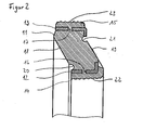
- FIG. 2 shows the section through a sealing body 11 for a mechanical seal, each with a stiffening ring 12, 13 on the radially inner 14 and outer 15 peripheral surface.
- the stiffening rings 12, 13 have openings 16, 17 which can be contained in the stiffening rings 12, 13 in the form of regular or irregularly arranged holes.
- the stiffening rings 12, 13 can also be made from perforated sheets.
- Strain relief devices 20, 21 are let into the axially outer surfaces 18, 19 of the sealing body 11.
- wave-shaped sealing profiles 22, 23 are formed, which can also be conical.
- Figure 3 shows the section through a drive seal 24, which by means of a trapezoidal sealing body 25 is mounted in a housing 26.
- a trapezoidal sealing body 25 On the radial Surface 27 of the sliding or counter ring 28 is the sealing body 25 by means of a Stiffening ring 29 fixed.
Landscapes
- Engineering & Computer Science (AREA)
- General Engineering & Computer Science (AREA)
- Mechanical Engineering (AREA)
- Mechanical Sealing (AREA)
Applications Claiming Priority (2)
| Application Number | Priority Date | Filing Date | Title |
|---|---|---|---|
| DE10216140 | 2002-04-12 | ||
| DE2002116140 DE10216140B4 (de) | 2002-04-12 | 2002-04-12 | Gleitringdichtung mit Verdrehsicherung |
Publications (3)
| Publication Number | Publication Date |
|---|---|
| EP1353099A2 true EP1353099A2 (fr) | 2003-10-15 |
| EP1353099A3 EP1353099A3 (fr) | 2004-02-04 |
| EP1353099B1 EP1353099B1 (fr) | 2006-07-05 |
Family
ID=28051269
Family Applications (1)
| Application Number | Title | Priority Date | Filing Date |
|---|---|---|---|
| EP20030007725 Expired - Lifetime EP1353099B1 (fr) | 2002-04-12 | 2003-04-04 | Garniture mécanique d'étanchéité avec dispositif d'arrêt en rotation |
Country Status (3)
| Country | Link |
|---|---|
| EP (1) | EP1353099B1 (fr) |
| DE (2) | DE10216140B4 (fr) |
| ES (1) | ES2268197T3 (fr) |
Cited By (3)
| Publication number | Priority date | Publication date | Assignee | Title |
|---|---|---|---|---|
| WO2007137640A1 (fr) * | 2006-05-31 | 2007-12-06 | Burgmann Industries Gmbh & Co. Kg | Bague de support pour anneau de glissement d'une garniture mécanique d'étanchéité |
| CN100513850C (zh) * | 2005-08-23 | 2009-07-15 | 浙江华夏阀门有限公司 | 三角截面密封套 |
| JP2014510239A (ja) * | 2011-02-17 | 2014-04-24 | フェデラル−モーグル ブルシャイト ゲゼルシャフト ミット ベシュレンクテル ハフツング | スライドリングシール |
Citations (2)
| Publication number | Priority date | Publication date | Assignee | Title |
|---|---|---|---|---|
| US3279804A (en) | 1963-07-05 | 1966-10-18 | Chicago Rawhide Mfg Co | End face seal assembly |
| DE1650024A1 (de) | 1967-11-16 | 1970-08-13 | Goetzewerke | Axiale Abdichtung fuer umlaufende Maschinenteile |
Family Cites Families (9)
| Publication number | Priority date | Publication date | Assignee | Title |
|---|---|---|---|---|
| US3336660A (en) * | 1962-11-13 | 1967-08-22 | Federal Mogul Corp | Face seals |
| DE6904242U (de) * | 1969-02-03 | 1969-04-30 | Goetze F Ag | Stuetzring fuer gleitringdichtungen |
| JPS589870B2 (ja) * | 1975-08-30 | 1983-02-23 | エヌオーケー株式会社 | メカニカルシ−ル |
| ES478722A1 (es) * | 1978-03-20 | 1979-07-01 | Goetze Ag | Perfeccionamientos en retenes frontales, especialmente para bombas. |
| DE3412594C2 (de) * | 1984-04-04 | 1986-07-31 | Goetze Ag, 5093 Burscheid | Gleitringdichtung |
| DE3739514C2 (de) * | 1987-11-21 | 1995-07-13 | Kaco Gmbh Co | Dichtring |
| GB9115991D0 (en) * | 1991-07-24 | 1991-09-11 | Crane John Uk Ltd | Mechanical face seals |
| DE4131472A1 (de) * | 1991-09-21 | 1993-03-25 | Schaeffler Waelzlager Kg | Radialwellendichtring aus elastomerem werkstoff |
| DE19955860B4 (de) * | 1999-11-20 | 2004-04-08 | Federal-Mogul Burscheid Gmbh | Gleitringdichtung |
-
2002
- 2002-04-12 DE DE2002116140 patent/DE10216140B4/de not_active Expired - Fee Related
-
2003
- 2003-04-04 DE DE50304111T patent/DE50304111D1/de not_active Expired - Lifetime
- 2003-04-04 ES ES03007725T patent/ES2268197T3/es not_active Expired - Lifetime
- 2003-04-04 EP EP20030007725 patent/EP1353099B1/fr not_active Expired - Lifetime
Patent Citations (2)
| Publication number | Priority date | Publication date | Assignee | Title |
|---|---|---|---|---|
| US3279804A (en) | 1963-07-05 | 1966-10-18 | Chicago Rawhide Mfg Co | End face seal assembly |
| DE1650024A1 (de) | 1967-11-16 | 1970-08-13 | Goetzewerke | Axiale Abdichtung fuer umlaufende Maschinenteile |
Cited By (5)
| Publication number | Priority date | Publication date | Assignee | Title |
|---|---|---|---|---|
| CN100513850C (zh) * | 2005-08-23 | 2009-07-15 | 浙江华夏阀门有限公司 | 三角截面密封套 |
| WO2007137640A1 (fr) * | 2006-05-31 | 2007-12-06 | Burgmann Industries Gmbh & Co. Kg | Bague de support pour anneau de glissement d'une garniture mécanique d'étanchéité |
| US8267406B2 (en) | 2006-05-31 | 2012-09-18 | Eagleburgmann Germany Gmbh & Co. Kg | Retaining ring for a seal ring of a mechanical seal assembly |
| JP2014510239A (ja) * | 2011-02-17 | 2014-04-24 | フェデラル−モーグル ブルシャイト ゲゼルシャフト ミット ベシュレンクテル ハフツング | スライドリングシール |
| US9574665B2 (en) | 2011-02-17 | 2017-02-21 | Federal-Mogul Burscheid Gmbh | Slide ring seal |
Also Published As
| Publication number | Publication date |
|---|---|
| DE50304111D1 (de) | 2006-08-17 |
| EP1353099A3 (fr) | 2004-02-04 |
| ES2268197T3 (es) | 2007-03-16 |
| DE10216140B4 (de) | 2004-07-08 |
| EP1353099B1 (fr) | 2006-07-05 |
| DE10216140A1 (de) | 2003-11-06 |
Similar Documents
| Publication | Publication Date | Title |
|---|---|---|
| DE102010001345B4 (de) | Drehdurchführung | |
| EP2459906B1 (fr) | Ensemble avec joint d'étanchéité | |
| DE2004046C2 (de) | Dichtung | |
| EP2035732B1 (fr) | Joint et ensemble joint | |
| EP0050213B1 (fr) | Logement des paliers à alignement automatique | |
| DE2654738A1 (de) | Schmiermitteldichtung | |
| AT520740B1 (de) | Zahnrad | |
| DE102011001868A1 (de) | Dichtkette | |
| EP3320240A1 (fr) | Passage tourant pour un véhicule | |
| EP0493731B1 (fr) | Flexibloc pour articulation | |
| DE102018102758A1 (de) | Feder für ein Rückschlagventil, Rückschlagventil mit einer derartigen Feder, regelbarer Schwingungsdämpfer mit einem solchen Rückschlagventil sowie Kraftfahrzeug mit einem derartigen regelbaren Schwingungsdämpfer | |
| DE102009058216B4 (de) | Dichtungsanordnung und Gelenk einer Kette mit der Dichtungsanordnung | |
| DE2726033A1 (de) | Dichtung, insbesondere fuer kettenbolzen an raupenschleppern o.dgl. | |
| WO2015022144A1 (fr) | Bague d'étanchéité | |
| WO2010009799A1 (fr) | Pompe centrifuge | |
| DE10113442C2 (de) | Lageranordnung für ein Wellenlager | |
| DE102014219859A1 (de) | Kreuzgelenk | |
| DE19637813C2 (de) | Gleitringdichtung | |
| EP1353099B1 (fr) | Garniture mécanique d'étanchéité avec dispositif d'arrêt en rotation | |
| DE102008024163A1 (de) | Verbundkolben für ein Kraftfahrzeuggetriebe | |
| EP1733150A1 (fr) | Soufflet d'etancheite | |
| DE102013216773A1 (de) | Radialwellendichtring zur Abdichtung eines Gehäuseteils eines Kraftfahrzeugmotors oder -getriebes gegen eine Welle | |
| DE10237966B4 (de) | Hydrolager mit Elastomerfeder | |
| DE3220192C1 (de) | Lippendichtungsring | |
| DE102008014222B3 (de) | Anordnung zum Verschleißausgleich bei insbesondere aus Kunststoff bestehenden sog. "Harmonic-Drive"-Getrieben |
Legal Events
| Date | Code | Title | Description |
|---|---|---|---|
| PUAI | Public reference made under article 153(3) epc to a published international application that has entered the european phase |
Free format text: ORIGINAL CODE: 0009012 |
|
| AK | Designated contracting states |
Kind code of ref document: A2 Designated state(s): AT BE BG CH CY CZ DE DK EE ES FI FR GB GR HU IE IT LI LU MC NL PT RO SE SI SK TR |
|
| AX | Request for extension of the european patent |
Extension state: AL LT LV MK |
|
| PUAL | Search report despatched |
Free format text: ORIGINAL CODE: 0009013 |
|
| AK | Designated contracting states |
Kind code of ref document: A3 Designated state(s): AT BE BG CH CY CZ DE DK EE ES FI FR GB GR HU IE IT LI LU MC NL PT RO SE SI SK TR |
|
| AX | Request for extension of the european patent |
Extension state: AL LT LV MK |
|
| 17P | Request for examination filed |
Effective date: 20040722 |
|
| AKX | Designation fees paid |
Designated state(s): DE ES FR GB IT |
|
| 17Q | First examination report despatched |
Effective date: 20040917 |
|
| GRAP | Despatch of communication of intention to grant a patent |
Free format text: ORIGINAL CODE: EPIDOSNIGR1 |
|
| GRAS | Grant fee paid |
Free format text: ORIGINAL CODE: EPIDOSNIGR3 |
|
| GRAA | (expected) grant |
Free format text: ORIGINAL CODE: 0009210 |
|
| AK | Designated contracting states |
Kind code of ref document: B1 Designated state(s): DE ES FR GB IT |
|
| PG25 | Lapsed in a contracting state [announced via postgrant information from national office to epo] |
Ref country code: IT Free format text: LAPSE BECAUSE OF FAILURE TO SUBMIT A TRANSLATION OF THE DESCRIPTION OR TO PAY THE FEE WITHIN THE PRESCRIBED TIME-LIMIT;WARNING: LAPSES OF ITALIAN PATENTS WITH EFFECTIVE DATE BEFORE 2007 MAY HAVE OCCURRED AT ANY TIME BEFORE 2007. THE CORRECT EFFECTIVE DATE MAY BE DIFFERENT FROM THE ONE RECORDED. Effective date: 20060705 |
|
| REG | Reference to a national code |
Ref country code: GB Ref legal event code: FG4D Free format text: NOT ENGLISH |
|
| GBT | Gb: translation of ep patent filed (gb section 77(6)(a)/1977) |
Effective date: 20060721 |
|
| REF | Corresponds to: |
Ref document number: 50304111 Country of ref document: DE Date of ref document: 20060817 Kind code of ref document: P |
|
| ET | Fr: translation filed | ||
| REG | Reference to a national code |
Ref country code: ES Ref legal event code: FG2A Ref document number: 2268197 Country of ref document: ES Kind code of ref document: T3 |
|
| PLBE | No opposition filed within time limit |
Free format text: ORIGINAL CODE: 0009261 |
|
| STAA | Information on the status of an ep patent application or granted ep patent |
Free format text: STATUS: NO OPPOSITION FILED WITHIN TIME LIMIT |
|
| 26N | No opposition filed |
Effective date: 20070410 |
|
| PGFP | Annual fee paid to national office [announced via postgrant information from national office to epo] |
Ref country code: FR Payment date: 20110331 Year of fee payment: 9 |
|
| PGFP | Annual fee paid to national office [announced via postgrant information from national office to epo] |
Ref country code: DE Payment date: 20110429 Year of fee payment: 9 Ref country code: ES Payment date: 20110425 Year of fee payment: 9 Ref country code: GB Payment date: 20110328 Year of fee payment: 9 |
|
| PGFP | Annual fee paid to national office [announced via postgrant information from national office to epo] |
Ref country code: IT Payment date: 20110416 Year of fee payment: 9 |
|
| GBPC | Gb: european patent ceased through non-payment of renewal fee |
Effective date: 20120404 |
|
| REG | Reference to a national code |
Ref country code: FR Ref legal event code: ST Effective date: 20121228 |
|
| PG25 | Lapsed in a contracting state [announced via postgrant information from national office to epo] |
Ref country code: GB Free format text: LAPSE BECAUSE OF NON-PAYMENT OF DUE FEES Effective date: 20120404 |
|
| REG | Reference to a national code |
Ref country code: DE Ref legal event code: R119 Ref document number: 50304111 Country of ref document: DE Effective date: 20121101 |
|
| PG25 | Lapsed in a contracting state [announced via postgrant information from national office to epo] |
Ref country code: IT Free format text: LAPSE BECAUSE OF NON-PAYMENT OF DUE FEES Effective date: 20120404 Ref country code: FR Free format text: LAPSE BECAUSE OF NON-PAYMENT OF DUE FEES Effective date: 20120430 |
|
| REG | Reference to a national code |
Ref country code: ES Ref legal event code: FD2A Effective date: 20130715 |
|
| PG25 | Lapsed in a contracting state [announced via postgrant information from national office to epo] |
Ref country code: ES Free format text: LAPSE BECAUSE OF NON-PAYMENT OF DUE FEES Effective date: 20120405 |
|
| PG25 | Lapsed in a contracting state [announced via postgrant information from national office to epo] |
Ref country code: DE Free format text: LAPSE BECAUSE OF NON-PAYMENT OF DUE FEES Effective date: 20121101 |