EP1353099B1 - Garniture mécanique d'étanchéité avec dispositif d'arrêt en rotation - Google Patents
Garniture mécanique d'étanchéité avec dispositif d'arrêt en rotation Download PDFInfo
- Publication number
- EP1353099B1 EP1353099B1 EP20030007725 EP03007725A EP1353099B1 EP 1353099 B1 EP1353099 B1 EP 1353099B1 EP 20030007725 EP20030007725 EP 20030007725 EP 03007725 A EP03007725 A EP 03007725A EP 1353099 B1 EP1353099 B1 EP 1353099B1
- Authority
- EP
- European Patent Office
- Prior art keywords
- sealing body
- ring
- mechanical seal
- radially outer
- sealing
- Prior art date
- Legal status (The legal status is an assumption and is not a legal conclusion. Google has not performed a legal analysis and makes no representation as to the accuracy of the status listed.)
- Expired - Lifetime
Links
- 238000007789 sealing Methods 0.000 claims description 90
- 239000013536 elastomeric material Substances 0.000 claims description 10
- 230000003014 reinforcing effect Effects 0.000 claims description 8
- 239000002184 metal Substances 0.000 claims 1
- 230000005540 biological transmission Effects 0.000 description 6
- 239000013013 elastic material Substances 0.000 description 4
- 230000002093 peripheral effect Effects 0.000 description 4
- 238000006073 displacement reaction Methods 0.000 description 3
- 238000004519 manufacturing process Methods 0.000 description 3
- 230000003068 static effect Effects 0.000 description 3
- 239000012535 impurity Substances 0.000 description 2
- 230000010354 integration Effects 0.000 description 2
- 239000007788 liquid Substances 0.000 description 2
- 239000000314 lubricant Substances 0.000 description 2
- 239000000725 suspension Substances 0.000 description 2
- 238000004026 adhesive bonding Methods 0.000 description 1
- 238000005452 bending Methods 0.000 description 1
- 238000010276 construction Methods 0.000 description 1
- 238000011109 contamination Methods 0.000 description 1
- 230000007797 corrosion Effects 0.000 description 1
- 238000005260 corrosion Methods 0.000 description 1
- 230000006735 deficit Effects 0.000 description 1
- 230000001419 dependent effect Effects 0.000 description 1
- 238000011161 development Methods 0.000 description 1
- 230000018109 developmental process Effects 0.000 description 1
- 230000000694 effects Effects 0.000 description 1
- 238000005516 engineering process Methods 0.000 description 1
- 238000012423 maintenance Methods 0.000 description 1
- 230000008092 positive effect Effects 0.000 description 1
Images
Classifications
-
- F—MECHANICAL ENGINEERING; LIGHTING; HEATING; WEAPONS; BLASTING
- F16—ENGINEERING ELEMENTS AND UNITS; GENERAL MEASURES FOR PRODUCING AND MAINTAINING EFFECTIVE FUNCTIONING OF MACHINES OR INSTALLATIONS; THERMAL INSULATION IN GENERAL
- F16J—PISTONS; CYLINDERS; SEALINGS
- F16J15/00—Sealings
- F16J15/16—Sealings between relatively-moving surfaces
- F16J15/34—Sealings between relatively-moving surfaces with slip-ring pressed against a more or less radial face on one member
- F16J15/3436—Pressing means
- F16J15/344—Pressing means the pressing force being applied by means of an elastic ring supporting the slip-ring
Definitions
- the invention relates to a mechanical seal, in particular drive seal, comprising an angular sliding and counter ring, which form a sealing surface with their radial sealing legs, and made of elastomeric material, trapezoidal sealing bodies, between the, the mechanical seal receiving housing and the radially outer surface of the axial Legs of the sliding and counter-ring are arranged, wherein the trapezoidal sealing bodies are equipped with a metallic stiffening ring and the sealing body has a stiffening ring which is arranged in the radially inner end of the trapezoidal sealing body wherein the connection between the sealing body and the radially outer surface of the axial leg of the Sliding and counter ring is tolerated as a press fit.
- the torques in a generic drive seal are transmitted from the sliding surfaces on the axial legs of the sliding and counter-rings and the sealing body on the housing. So that the torques of the axial limbs of the sliding and counter rings can be transmitted to the sealing body, sufficient static friction must be present at this connection point.
- the force exerted by the sealing bodies on the sliding and counter rings u. a. be controlled by the inclination and the dimensions of the trapezoidal sealing body.
- 16 50 024 is proposed in DE OS to integrate a metallic suspension body in the sealing body.
- a loose between sliding ring and machine housing einulegender sealing body to be created which allows for the simplest design a relatively large axial movement of the slide ring, without losing the rotationally fixed contact on both Gleitring Wegen and on the machine housing.
- Such an integration of a suspension body ensures that, in the case of an axial displacement of the sliding ring, the sealing body is subjected both to pressure and to bending, in contrast to the usual shear stress in the known sealing bodies.
- the power flow is specifically influenced in the sealing body, a tilting of the sealing body can not be prevented.
- sealing body Due to the inventive design of the sealing body, it is now possible to ensure an optimal connection of the sealing body to the sliding ring and thus a secure transmission of torque.
- the wavy, elastomeric sealing profile offers the possibility of easy assembly and on the other hand is ensured by the wave profile that the elastomeric material is not overstretched. An over-claim can not be made because the excess, elastomeric material can dodge during assembly in the troughs.
- the dimensioning between the radially inner surface of the sealing body and the radially outer surface of the sliding and counter rings is designed as a press fit. There is therefore no loose connection, but the components are held together positively.
- other forces available which increase the static friction and support an optimal transmission of torque. So even the largest torques, as z. B. when gluing the sliding surfaces caused by dirt or corrosion, are transmitted.
- Another inventive advantage results from the interference fit to the effect that the components during assembly can not fall apart and that no displacement of the sealing body, can be done with Jerusalem constructing dirt on the slide ring.
- the height of the elastomeric sealing profile is low and is in the range of about one to a few millimeters. Due to the small height of the wave-shaped sealing profile of the sealing body is subject to only a small setting, which in turn has a positive effect on the maintenance behavior and the transmission of torque.
- tensile stresses in the sealing bodies Due to the axial and radial movements of the sliding or counter rings, there are, among other things, tensile stresses in the sealing bodies. These tensile stresses reach the outer surfaces of the sealing body their maximum. So that the connection between the sealing body and stiffening ring are subjected to maximum load at these points. To minimize these loads and / or deflect a strain relief is formed in these areas in the sealing body.
- the strain relief is formed in the form of a groove-shaped undercut directly in the connection region between the elastomeric material and stiffening ring to the sealing body.
- the outer circumferential surfaces of the axial limbs of the sliding and counter rings slightly conical. Due to the slightly conical design, the assembly is facilitated, but the connection always remains executed as a press fit.
- the conical design of the sliding and counter rings follows the sealing body characterized in that the elastomeric material, with the wave-shaped profiling, also conical on the inner circumference of the stiffening ring, so that the surfaces of the components are always parallel when joining.
- a further stiffening ring in the sealing body.
- This stiffening ring is inventively introduced into the radially outer end of the sealing body and also has, on its side facing the housing, a wave-shaped sealing profile. Based on the fitting dimensions, this connection is also designed as a press fit.
- a strain relief in the form of an undercut can also be formed here.
- the stiffening ring is exposed to more or less high pressures during mold filling.
- the liquid, elastomeric material must flow around the stiffening ring, which in turn could lead to deformation of the stiffening ring. Therefore, it is proposed in the invention to provide the stiffening ring with openings, so that the liquid, elastomeric material can flow through the stiffening ring during mold filling.
- a stiffening ring according to the invention into the sealing body is intended for the type of drive seals in which, due to the size of the construction, a form-fitting torque transmission can only be produced with great difficulty in terms of manufacturing technology.
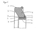
- FIG. 1 shows the section through a sealing body 1 according to the invention for a mechanical seal, comprising a trapezoidal sealing body 2, a stiffening ring 3 and a wave-shaped sealing profile.
- the stiffening ring 3 is made due to production L-shaped, while the short leg is directed radially outward.
- 1 notches 6 are embedded in the sealing body.
- the strain relief 8 is executed in this embodiment as an approximately circular undercut.
- a further sealing profile 4 is formed at the radially inner peripheral surface 9 of the sealing body 1.
- the surface is wave-shaped 10 and may also be conical depending on the sliding or counter ring.
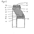
- FIG. 2 shows the section through a sealing body 11 for a mechanical seal, each with a stiffening ring 12, 13 on the radially inner 14 and the outer 15 peripheral surface.
- the stiffening rings 12, 13 have openings 16, 17, which may be contained in the stiffening rings 12, 13 in the form of regular or irregularly arranged holes.
- the stiffening rings 12, 13 are also made of perforated plates.
- strain reliefs 20, 21 are embedded in the axially outer surfaces 18, 19 of the sealing body 11 strain reliefs 20, 21 are embedded.
- wave-shaped sealing profiles 22, 23 are formed, which can also be conical.
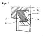
- FIG. 3 shows the section through a drive seal 24, which is mounted in a housing 26 by means of a trapezoidal sealing body 25.
- the sealing body 25 is fixed by means of a stiffening ring 29.
Landscapes
- Engineering & Computer Science (AREA)
- General Engineering & Computer Science (AREA)
- Mechanical Engineering (AREA)
- Mechanical Sealing (AREA)
Claims (5)
- Garniture mécanique d'étanchéité à anneau de glissement, en particulier garniture d'étanchéité pour mécanisme de roulement (24), comportant une bague de glissement et de butée (28) de forme angulaire, dont les branches d'étanchéité radiales forment une surface d'étanchéité, et des corps d'étanchéité (1, 11, 25) de forme trapézoïdale réalisés dans un matériau élastomère, qui sont agencés entre le carter (26) recevant la garniture mécanique d'étanchéité et la surface radialement extérieure des branches (27) axiales de la bague de glissement et de butée, les corps d'étanchéité (1, 11, 25) trapézoïdaux étant munis d'une frette (3, 12, 13, 29) métallique et le corps d'étanchéité (1, 11, 25) comportant une frette métallique (3, 12, 29) qui est agencée dans l'extrémité radialement intérieure du corps d'étanchéité (1, 11, 25) trapézoïdal, la liaison entre le corps d'étanchéité (1, 11, 25) et la surface radialement extérieure des branches (27) axiales de la bague de glissement et de butée étant tolérée sous la forme d'un ajustement serré, caractérisée en ce qu'un profil d'étanchéité (4, 22, 23) élastomère de forme ondulée est agencé sur la frette (3, 12, 29) en direction des surfaces radialement extérieures des branches axiales de la bague de glissement et de butée et en ce qu'une décharge de traction (8, 20) en forme de contre-dépouille, en particulier en forme de rayon, est réalisée sur l'extrémité radialement extérieure (7) du corps d'étanchéité (1, 11, 25) trapézoïdal, directement au-dessus de la surface radialement extérieure de la frette (3, 12, 29).
- Garniture mécanique d'étanchéité selon la revendication 1, caractérisée en ce que le diamètre de la surface radialement extérieure des branches axiales de la bague de glissement et de butée diminue vers l'extrémité radialement extérieure, de telle sorte qu'il se forme une liaison légèrement conique entre le corps d'étanchéité (1) et la bague de glissement et de butée.
- Garniture mécanique d'étanchéité selon l'une quelconque des revendications 1 à 2, caractérisée en ce que, dans l'extrémité radialement extérieure du corps d'étanchéité (11) trapézoïdal, au niveau du carter recevant la garniture mécanique d'étanchéité, est prévue une frette (13) supplémentaire, sur la surface radialement extérieure de laquelle, est prévu un profil d'étanchéité (23) de forme ondulée et en ce que la liaison entre la surface radialement extérieure du profil d'étanchéité (23) et le carter est tolérée sous forme d'ajustement serré.
- Garniture mécanique d'étanchéité selon la revendication 3, caractérisée en ce que, sur l'extrémité radialement intérieure (19) du corps d'étanchéité (11) trapézoïdal, directement en dessous de l'extrémité radiale de la frette (13), est réalisée une décharge de traction (21) en forme de contre-dépouille, en particulier en forme de rayon.
- Garniture mécanique d'étanchéité selon l'une quelconque des revendications 1 à 4, caractérisée en ce que des orifices (16, 17) sont prévus dans la frette (3, 12, 13, 29), de telle sorte qu'une liaison est formée entre le profil d'étanchéité (4, 22, 23) de forme ondulée et le corps d'étanchéité (1, 11, 25) de forme trapézoïdale.
Applications Claiming Priority (2)
| Application Number | Priority Date | Filing Date | Title |
|---|---|---|---|
| DE10216140 | 2002-04-12 | ||
| DE2002116140 DE10216140B4 (de) | 2002-04-12 | 2002-04-12 | Gleitringdichtung mit Verdrehsicherung |
Publications (3)
| Publication Number | Publication Date |
|---|---|
| EP1353099A2 EP1353099A2 (fr) | 2003-10-15 |
| EP1353099A3 EP1353099A3 (fr) | 2004-02-04 |
| EP1353099B1 true EP1353099B1 (fr) | 2006-07-05 |
Family
ID=28051269
Family Applications (1)
| Application Number | Title | Priority Date | Filing Date |
|---|---|---|---|
| EP20030007725 Expired - Lifetime EP1353099B1 (fr) | 2002-04-12 | 2003-04-04 | Garniture mécanique d'étanchéité avec dispositif d'arrêt en rotation |
Country Status (3)
| Country | Link |
|---|---|
| EP (1) | EP1353099B1 (fr) |
| DE (2) | DE10216140B4 (fr) |
| ES (1) | ES2268197T3 (fr) |
Families Citing this family (3)
| Publication number | Priority date | Publication date | Assignee | Title |
|---|---|---|---|---|
| CN100513850C (zh) * | 2005-08-23 | 2009-07-15 | 浙江华夏阀门有限公司 | 三角截面密封套 |
| DE202006008635U1 (de) * | 2006-05-31 | 2006-08-03 | Burgmann Industries Gmbh & Co. Kg | Trägerring für einen Gleitring einer Gleitringdichtungsanordnung |
| DE102011011475B4 (de) | 2011-02-17 | 2012-09-27 | Federal-Mogul Burscheid Gmbh | Gleitringdichtung |
Family Cites Families (11)
| Publication number | Priority date | Publication date | Assignee | Title |
|---|---|---|---|---|
| US3336660A (en) * | 1962-11-13 | 1967-08-22 | Federal Mogul Corp | Face seals |
| US3279804A (en) * | 1963-07-05 | 1966-10-18 | Chicago Rawhide Mfg Co | End face seal assembly |
| DE1650024A1 (de) * | 1967-11-16 | 1970-08-13 | Goetzewerke | Axiale Abdichtung fuer umlaufende Maschinenteile |
| DE6904242U (de) * | 1969-02-03 | 1969-04-30 | Goetze F Ag | Stuetzring fuer gleitringdichtungen |
| JPS589870B2 (ja) * | 1975-08-30 | 1983-02-23 | エヌオーケー株式会社 | メカニカルシ−ル |
| ES478722A1 (es) * | 1978-03-20 | 1979-07-01 | Goetze Ag | Perfeccionamientos en retenes frontales, especialmente para bombas. |
| DE3412594C2 (de) * | 1984-04-04 | 1986-07-31 | Goetze Ag, 5093 Burscheid | Gleitringdichtung |
| DE3739514C2 (de) * | 1987-11-21 | 1995-07-13 | Kaco Gmbh Co | Dichtring |
| GB9115991D0 (en) * | 1991-07-24 | 1991-09-11 | Crane John Uk Ltd | Mechanical face seals |
| DE4131472A1 (de) * | 1991-09-21 | 1993-03-25 | Schaeffler Waelzlager Kg | Radialwellendichtring aus elastomerem werkstoff |
| DE19955860B4 (de) * | 1999-11-20 | 2004-04-08 | Federal-Mogul Burscheid Gmbh | Gleitringdichtung |
-
2002
- 2002-04-12 DE DE2002116140 patent/DE10216140B4/de not_active Expired - Fee Related
-
2003
- 2003-04-04 DE DE50304111T patent/DE50304111D1/de not_active Expired - Lifetime
- 2003-04-04 ES ES03007725T patent/ES2268197T3/es not_active Expired - Lifetime
- 2003-04-04 EP EP20030007725 patent/EP1353099B1/fr not_active Expired - Lifetime
Also Published As
| Publication number | Publication date |
|---|---|
| DE50304111D1 (de) | 2006-08-17 |
| EP1353099A3 (fr) | 2004-02-04 |
| ES2268197T3 (es) | 2007-03-16 |
| DE10216140B4 (de) | 2004-07-08 |
| EP1353099A2 (fr) | 2003-10-15 |
| DE10216140A1 (de) | 2003-11-06 |
Similar Documents
| Publication | Publication Date | Title |
|---|---|---|
| DE3320063C2 (fr) | ||
| DE2004046C2 (de) | Dichtung | |
| EP2035732B1 (fr) | Joint et ensemble joint | |
| DE68910952T2 (de) | Deckelbefestigung für eine Luftfeder. | |
| EP3554968B1 (fr) | Rouleau de manutention doté d'une douille d'accouplement entraînée par friction et/ou par continuité de matière | |
| DE3840691C2 (de) | Radialkolbenpumpe | |
| WO2011092111A2 (fr) | Ensemble joint d'étanchéité rotatif | |
| DE2654738A1 (de) | Schmiermitteldichtung | |
| WO2011012129A1 (fr) | Joint détanchéité et ensemble joint détanchéité | |
| DE102007049704A1 (de) | Innenzahnradpumpe für eine Bremsanlage | |
| EP0493731B1 (fr) | Flexibloc pour articulation | |
| DE3517959C2 (fr) | ||
| DE102018102758A1 (de) | Feder für ein Rückschlagventil, Rückschlagventil mit einer derartigen Feder, regelbarer Schwingungsdämpfer mit einem solchen Rückschlagventil sowie Kraftfahrzeug mit einem derartigen regelbaren Schwingungsdämpfer | |
| EP3872373B1 (fr) | Bague d'étanchéité et son utilisation | |
| WO2015022144A1 (fr) | Bague d'étanchéité | |
| DE10113442C2 (de) | Lageranordnung für ein Wellenlager | |
| WO2010009799A1 (fr) | Pompe centrifuge | |
| DE102014219859A1 (de) | Kreuzgelenk | |
| EP1353099B1 (fr) | Garniture mécanique d'étanchéité avec dispositif d'arrêt en rotation | |
| EP0656462B1 (fr) | Dispositif d'étanchéité | |
| DE102014219858A1 (de) | Kreuzgelenk | |
| WO2014108122A1 (fr) | Joint d'étanchéité pour un ensemble hydraulique piston-cylindre | |
| EP0116721A1 (fr) | Joint d'arbre | |
| DE10356162A1 (de) | Lastglied für eine Stirnseitendichtung | |
| DE10237966B4 (de) | Hydrolager mit Elastomerfeder |
Legal Events
| Date | Code | Title | Description |
|---|---|---|---|
| PUAI | Public reference made under article 153(3) epc to a published international application that has entered the european phase |
Free format text: ORIGINAL CODE: 0009012 |
|
| AK | Designated contracting states |
Kind code of ref document: A2 Designated state(s): AT BE BG CH CY CZ DE DK EE ES FI FR GB GR HU IE IT LI LU MC NL PT RO SE SI SK TR |
|
| AX | Request for extension of the european patent |
Extension state: AL LT LV MK |
|
| PUAL | Search report despatched |
Free format text: ORIGINAL CODE: 0009013 |
|
| AK | Designated contracting states |
Kind code of ref document: A3 Designated state(s): AT BE BG CH CY CZ DE DK EE ES FI FR GB GR HU IE IT LI LU MC NL PT RO SE SI SK TR |
|
| AX | Request for extension of the european patent |
Extension state: AL LT LV MK |
|
| 17P | Request for examination filed |
Effective date: 20040722 |
|
| AKX | Designation fees paid |
Designated state(s): DE ES FR GB IT |
|
| 17Q | First examination report despatched |
Effective date: 20040917 |
|
| GRAP | Despatch of communication of intention to grant a patent |
Free format text: ORIGINAL CODE: EPIDOSNIGR1 |
|
| GRAS | Grant fee paid |
Free format text: ORIGINAL CODE: EPIDOSNIGR3 |
|
| GRAA | (expected) grant |
Free format text: ORIGINAL CODE: 0009210 |
|
| AK | Designated contracting states |
Kind code of ref document: B1 Designated state(s): DE ES FR GB IT |
|
| PG25 | Lapsed in a contracting state [announced via postgrant information from national office to epo] |
Ref country code: IT Free format text: LAPSE BECAUSE OF FAILURE TO SUBMIT A TRANSLATION OF THE DESCRIPTION OR TO PAY THE FEE WITHIN THE PRESCRIBED TIME-LIMIT;WARNING: LAPSES OF ITALIAN PATENTS WITH EFFECTIVE DATE BEFORE 2007 MAY HAVE OCCURRED AT ANY TIME BEFORE 2007. THE CORRECT EFFECTIVE DATE MAY BE DIFFERENT FROM THE ONE RECORDED. Effective date: 20060705 |
|
| REG | Reference to a national code |
Ref country code: GB Ref legal event code: FG4D Free format text: NOT ENGLISH |
|
| GBT | Gb: translation of ep patent filed (gb section 77(6)(a)/1977) |
Effective date: 20060721 |
|
| REF | Corresponds to: |
Ref document number: 50304111 Country of ref document: DE Date of ref document: 20060817 Kind code of ref document: P |
|
| ET | Fr: translation filed | ||
| REG | Reference to a national code |
Ref country code: ES Ref legal event code: FG2A Ref document number: 2268197 Country of ref document: ES Kind code of ref document: T3 |
|
| PLBE | No opposition filed within time limit |
Free format text: ORIGINAL CODE: 0009261 |
|
| STAA | Information on the status of an ep patent application or granted ep patent |
Free format text: STATUS: NO OPPOSITION FILED WITHIN TIME LIMIT |
|
| 26N | No opposition filed |
Effective date: 20070410 |
|
| PGFP | Annual fee paid to national office [announced via postgrant information from national office to epo] |
Ref country code: FR Payment date: 20110331 Year of fee payment: 9 |
|
| PGFP | Annual fee paid to national office [announced via postgrant information from national office to epo] |
Ref country code: DE Payment date: 20110429 Year of fee payment: 9 Ref country code: ES Payment date: 20110425 Year of fee payment: 9 Ref country code: GB Payment date: 20110328 Year of fee payment: 9 |
|
| PGFP | Annual fee paid to national office [announced via postgrant information from national office to epo] |
Ref country code: IT Payment date: 20110416 Year of fee payment: 9 |
|
| GBPC | Gb: european patent ceased through non-payment of renewal fee |
Effective date: 20120404 |
|
| REG | Reference to a national code |
Ref country code: FR Ref legal event code: ST Effective date: 20121228 |
|
| PG25 | Lapsed in a contracting state [announced via postgrant information from national office to epo] |
Ref country code: GB Free format text: LAPSE BECAUSE OF NON-PAYMENT OF DUE FEES Effective date: 20120404 |
|
| REG | Reference to a national code |
Ref country code: DE Ref legal event code: R119 Ref document number: 50304111 Country of ref document: DE Effective date: 20121101 |
|
| PG25 | Lapsed in a contracting state [announced via postgrant information from national office to epo] |
Ref country code: IT Free format text: LAPSE BECAUSE OF NON-PAYMENT OF DUE FEES Effective date: 20120404 Ref country code: FR Free format text: LAPSE BECAUSE OF NON-PAYMENT OF DUE FEES Effective date: 20120430 |
|
| REG | Reference to a national code |
Ref country code: ES Ref legal event code: FD2A Effective date: 20130715 |
|
| PG25 | Lapsed in a contracting state [announced via postgrant information from national office to epo] |
Ref country code: ES Free format text: LAPSE BECAUSE OF NON-PAYMENT OF DUE FEES Effective date: 20120405 |
|
| PG25 | Lapsed in a contracting state [announced via postgrant information from national office to epo] |
Ref country code: DE Free format text: LAPSE BECAUSE OF NON-PAYMENT OF DUE FEES Effective date: 20121101 |