EP1354548A2 - Appareil d'entretien du sol avec une contre-force - Google Patents
Appareil d'entretien du sol avec une contre-force Download PDFInfo
- Publication number
- EP1354548A2 EP1354548A2 EP03252337A EP03252337A EP1354548A2 EP 1354548 A2 EP1354548 A2 EP 1354548A2 EP 03252337 A EP03252337 A EP 03252337A EP 03252337 A EP03252337 A EP 03252337A EP 1354548 A2 EP1354548 A2 EP 1354548A2
- Authority
- EP
- European Patent Office
- Prior art keywords
- handle
- deck
- force
- floor
- floor care
- Prior art date
- Legal status (The legal status is an assumption and is not a legal conclusion. Google has not performed a legal analysis and makes no representation as to the accuracy of the status listed.)
- Withdrawn
Links
Images
Classifications
-
- A—HUMAN NECESSITIES
- A47—FURNITURE; DOMESTIC ARTICLES OR APPLIANCES; COFFEE MILLS; SPICE MILLS; SUCTION CLEANERS IN GENERAL
- A47L—DOMESTIC WASHING OR CLEANING; SUCTION CLEANERS IN GENERAL
- A47L11/00—Machines for cleaning floors, carpets, furniture, walls, or wall coverings
- A47L11/40—Parts or details of machines not provided for in groups A47L11/02 - A47L11/38, or not restricted to one of these groups, e.g. handles, arrangements of switches, skirts, buffers, levers
- A47L11/4072—Arrangement of castors or wheels
-
- A—HUMAN NECESSITIES
- A47—FURNITURE; DOMESTIC ARTICLES OR APPLIANCES; COFFEE MILLS; SPICE MILLS; SUCTION CLEANERS IN GENERAL
- A47L—DOMESTIC WASHING OR CLEANING; SUCTION CLEANERS IN GENERAL
- A47L11/00—Machines for cleaning floors, carpets, furniture, walls, or wall coverings
- A47L11/02—Floor surfacing or polishing machines
- A47L11/10—Floor surfacing or polishing machines motor-driven
- A47L11/14—Floor surfacing or polishing machines motor-driven with rotating tools
- A47L11/16—Floor surfacing or polishing machines motor-driven with rotating tools the tools being disc brushes
- A47L11/162—Floor surfacing or polishing machines motor-driven with rotating tools the tools being disc brushes having only a single disc brush
-
- A—HUMAN NECESSITIES
- A47—FURNITURE; DOMESTIC ARTICLES OR APPLIANCES; COFFEE MILLS; SPICE MILLS; SUCTION CLEANERS IN GENERAL
- A47L—DOMESTIC WASHING OR CLEANING; SUCTION CLEANERS IN GENERAL
- A47L11/00—Machines for cleaning floors, carpets, furniture, walls, or wall coverings
- A47L11/40—Parts or details of machines not provided for in groups A47L11/02 - A47L11/38, or not restricted to one of these groups, e.g. handles, arrangements of switches, skirts, buffers, levers
- A47L11/4075—Handles; levers
Definitions
- the present invention relates generally to a floor care machine, and in particular to a floor care machine which automatically maintains a substantially even pressure on the floor by a floor care element attached to the machine.
- weight control is important in controlling the pressure applied to the floor surface and in controlling the amperage draw of the motor of the floor care machine.
- weight control has been generally accomplished by a floor care machine operator using a fixed handle on the floor care machine to manually determine the amount of pressure being applied to various floor areas. In particular, the operator controlled the floor care element pressure by lifting or pushing on the handle.
- a floor care machine comprising:
- a floor care machine comprising:
- a method for controlling a position of a floor care element comprising:
- Embodiments of the present invention may provide a floor care machine that provides a coupling or a handle link between the floor care machine body and a handle apparatus which is pivotally mounted to the body.
- the handle link is part of a force generating system having a resilient compressible component (e.g., a compression spring) along the direction of the length of the handle apparatus, wherein the compressible component and the handle link cooperate for urging the body (or deck) of the floor care machine to pivot about the axis of a first set of wheels and thereby bias the front of the deck upwardly.
- the forces for urging the deck to pivot are used to counter balance opposing pivotal forces caused by the weight of the deck and the floor suction forces generated by the rotation of a floor care element that rotationally contacts the floor for administering the desired floor care when the machine is operating.
- embodiments of the present invention seek to provide a novel machine for the care of floor surfaces.
- Embodiments of the present invention further seek to provide such a novel floor care machine which places a substantially even pressure on the floor surface by the floor care element substantially without regard to the pivotal position of the handle apparatus with respect to the deck of the floor care machine.
- Embodiments of the present invention also seek to provide such a novel floor care machine which places even polishing force on the floor surface by the floor care element regardless of the unevenness of the floor surface.
- Embodiments of the present invention also seek to provide such a novel floor care machine which automatically maintains even polishing pressure.
- Embodiments of the present invention also seek to provide such a novel floor care machine which maintains even floor care element pressure without being dependent on operator involvement.
- Embodiments of the present invention also seek to provide such a novel floor care machine having floor care element pressure which is not variable due to operation by different operators.
- Embodiments of the present invention also seek to provide such a novel floor care machine having floor care element pressure which is substantially not variable due to operator fatigue.
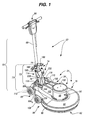
- the floor care machine 50 generally includes a body portion or deck 54 adapted to be moved along a floor 58 (Fig. 2), and, attached to the deck is a floor care element 62 including, e.g., a polishing pad, a brush, a burnishing pad, a sanding disk, a waxing pad, a floor scouring element, or the like which contacts the floor with a rotational motion when the floor care machine 50 is operable. Additionally, the deck 54 has attached thereto a handle apparatus 64 for guiding and controlling the deck 54.
- a handle apparatus 64 for guiding and controlling the deck 54.
- the handle apparatus 64 is pivotally attached to the deck 54 at various locations on the deck (as will be described below) so that the handle apparatus can, e.g., pivot between (i) operating positions (wherein the below described handle 68 is generally within a range of 30 to 60 degrees from the horizontal but can be outside that range), and (ii) a transport position (wherein the handle 68 is substantially vertical).
- the deck 54 also includes a housing 78 which substantially contains the floor care element 62.
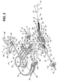
- the housing 78 includes a sloping platform 82 having a downwardly extending skirt 84 about its perimeter, wherein the skirt includes a first skirt portion 86 surrounding the floor care element 62 and a second skirt portion 88 extending rearwardly, e.g., for attaching the handle apparatus 64 thereto (Fig. 3), wherein this second skirt portion includes paired planar sides (88a L , 88a R ), (88b L , 88b R ) and a rear skirting 88c (e.g., Fig. 3).
- a motor 90 is mounted at the center of and generally above the platform 82.
- Floor care element 62 is operatively connected to motor 90 for rotation thereby and within housing 78.
- the deck 54 further includes a substantially inverted cup-shaped housing or motor shroud 94 received on housing 78 for encasing motor 90.
- the housing 94 generally includes a cylindrical shaped portion 98 and a generally box shaped portion 102.
- Portion 102 includes a generally closed top 106, a generally open bottom for receipt and mating on platform 82.
- the floor care machine 50 further includes a first set of wheels 108 having a rotation axis located intermediate between the motor 90 and a second set of wheels 110.
- the first set of wheels 108 is generally at a level equal to or slightly lower than the level of floor care element 62.
- the front two-thirds of the floor care element 62 i.e., from the 8 o'clock to 4 o'clock position thereof
- the wheels 108 are rotatably secured to the skirt 84 of the housing 78.
- the counter force assembly 70 For attaching the handle apparatus 64 to the deck 54, the counter force assembly 70 includes mounts 116 that extend from the center axis 118 (Fig. 3) of the handle apparatus 64, and span the rear skirting 88c. The mounts 116 are pivotally secured to the deck 54 via an axle 120 (Fig. 3) that is provided through the planar skirting sides 88b L and 88b R and additionally through an axle opening 122 in each mount 116.
- the counter force assembly 70 includes force system 72 which, in turn, includes the force generating device 74 that is generally provided along center axis 118 and below the handle 68 (Fig. 1).
- the force generating device 74 includes adjacent lower handle sides 130 (Fig. 3) which provide a substantially cylindrical chamber 136 (Fig.
- this chamber extends: (a) from paired chamber end cap halves 142 (only one of which can be seen in Fig. 3) to (b) the brackets 146.
- the cylindrical chamber 136 has its center axis aligned with the center axis 118 of the handle apparatus 64.
- each of the lower handle sides 130 has a guide slot 152 extending longitudinally from just below the brackets 146 and toward the end cap halves 142 for approximately 1/3 of the length of the cylindrical chamber 136 in the direction of the center axis 118. Also, in the region 158 (Fig.
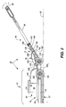
- each of the lower handle sides 130 provides for the cylindrical chamber 136 to have a larger radius than the lower portion 160 of the cylindrical chamber 136 (Fig. 2) below the regions 158.
- the lower end of the handle 68 is secured within the enlarged radius portion provided by the two regions 158 when these regions are secured together by anyone of various securing devices such as bolt assembly 164 (Fig. 3).
- the bolt assembly 164 secures the adjacent lower handle sides 130 with the handle 68 by remaining positioned in the bolt holes 168, 172, and 176.
- the counter pivot force is provided by the generation of a force linearly along the center axis 118 by the compression of a compressible component such as compression spring 182.
- a compressible component such as compression spring 182.
- another component such as a wave spring or other resilient component may be used in place of compression spring 182, and such resilient components may have different resiliency characteristics depending, e.g., on the desired behavior of the floor care machine 50.
- a compression block 186 for compressing the spring 182 within the lower portion 160.
- the compression block 186 has a diameter that may be only sufficiently smaller than the diameter of the lower portion 160 so that the compression block can freely slide therein.
- the compression block 186 is slidably secured to the guide slots 152 by bolt assembly 190 (Fig. 3) also included in the force generating device 74, wherein bolt shaft 194 and sleeve 198 of this bolt assembly securely span both guide slots 152 and the bolt hole 204 of the compression block 186.
- Also pivotally secured to the bolt shaft 194 and the sleeve 198 is a first end portion 208 (via bolt holes 212) of the handle link 76, wherein the opposite end 220 of the handle link pivotally attaches to the deck 54 as will be described hereinbelow.
- side flanges 226 and the cross member 230 of the handle link 76 fit over the lower portion 160.
- this end is pivotally secured to the deck 54, and when the angular orientation between the handle apparatus 64 and the deck 54 changes, each end 208 and 220 of the handle link 76 pivots in a manner such that bolt assembly 190 changes position in the guide slots 152.
- the bolt assembly 190 is urged toward the upper end of the guide slots 152 and the spring 182 is decompressed.
- the angle between the handle 68 and such an horizontal surface increases (e.g., toward 180 degrees)
- the bolt assembly 190 is urged toward the lower end of the guide slots 152 and accordingly compresses spring 182.
- the end 220 is pivotally attached to the deck 54 (by pin subassembly 236 having components identified by the same label) within a raised enclosure 244 of the deck.
- the operator changes the angle of the handle apparatus 64 relative to the horizontal, such a change will induce a linear movement of the bolt assembly 190 (and also the spring 182 and compression block 186) within the lower portion 160, and there will be a responsive movement by the handle link 76 which will cause the pressure exerted by the rotating floor care element 62 to at least temporarily change due to a pivoting force of the deck 54 about the axle 120.
- a spring 182 requiring very high forces for compressing will cause the handle link 54 to move more similarly to having its end 208 remain in a constant pivot position along the axis 118 and thus any angular change (relative to the horizontal) between the handle apparatus 64 and the deck 54 will be substantially fully communicated between these two assemblies.
- spring 182 requires very small forces for compression, then an angular change (relative to the horizontal) between the handle apparatus 64 and the deck 54 will for the most part not be communicated from one of these two assemblies to the other.
- the responsiveness of the floor care machine 50 to angular changes between the handle apparatus 64 and the deck 54 can be changed.
- the collection of components for the latch mechanism includes a torsion spring 254 (Fig. 3) disposed on the pin subassembly 236 for biasing the handle link 76 (and accordingly, the handle 68) to pivot clockwise (in the orientation of Fig. 2) about this pin subassembly toward a position for operating the floor care machine 50 rather than storing it.
- the handle apparatus 64 when storing the floor care machine 50, the handle apparatus 64 is rotated to a substantially vertical position by overcoming the bias of the torsion spring 254 and causing the latching mechanism to secure the handle apparatus 64 in the substantially vertical position.
- the collection of components for the latch mechanism includes a latch 258 (Fig. 3) pivotally provided on the pin subassembly 236 and within the raised enclosure 244 for receiving a latch striker 262 provided on the end of the handle apparatus 64 opposite from the grip 66. Note that the latch 258 and the latch striker 262 cooperate to secure the handle apparatus 64 in a substantially vertical position for storing the floor care machine 50.
- the wheels 110 are positioned at a level slightly above the level of the floor care element 62. In one embodiment, the wheels 110 are in the range of 1 ⁇ 2 to 3 ⁇ 4 of an inch above the level of wheels 108.
- the force system 72 may induce pivoting forces at the axle 120 that: (a) are counter pivot forces to the gravitational and floor suction forces which the deck 54 exerts about the axle 120, and (b) reduce the possibility of (or the degree to which) the floor care element 62 unevenly or differently contacts the floor when, e.g., undulations in the floor 58 are encountered, and/or different handle apparatus 64 orientations are used by different floor care machine operators.
- both operators can cause the floor care element 62 to exert substantially the same pressure on the floor 58 during operation of the floor care machine 50.
- the spring 182 (or other compressible component) must be matched to the weight and suction forces generated by the deck 54. In general, for many springs 182 there is a non-trivial range of angles relative to the horizontal wherein there is only a slight variation in the linear force generated by the spring 182.
- such a range can correspond to the handle apparatus 64 varying between 35 degrees to 50 degrees from horizontal (i.e., counter clockwise in Fig. 2).
- the linear force generated by the spring 182 may commence to vary noticeably, and such variation can be beneficial in that an operator can then explicitly cause the floor care element 62 to vary its pressure on the floor 58 to correspond to different floor conditions such as, e.g., exceptionally soiled areas of the floor 58.
- the latch striker 262 is disengaged from the latch 258 allowing handle apparatus 64, including handle 68 and the force generating portions 74, such as the compression spring 182, to be pivotal with respect to the deck 54 about pivot pin subassembly 236 and axle 120.
- torsion spring 254 biases the handle apparatus 64 from a substantially vertical position and towards an angled position (e.g., 45 degrees) with respect to horizontal.
- handle apparatus 64 When the handle apparatus 64 is lowered into its operating position as shown in Fig. 2, handle apparatus 64 creates a load on the spring 182. This load or force translates into a clockwise pivot force on the wheels 108 (in the orientation of Fig. 2) so that there is a downward force to the rear of platform 82 which, in turn, causes an upward lift to the front of platform 82.
- deck 54 will pivot about wheels 108 such that the forward portion of deck 54 and of floor care element 62 is raised above the floor 58 since there is no floor suction force being provided at the front of the floor care machine 50.
- an operator can then tilt the floor care machine 50 back so that it can be moved on both sets of wheels 108 and 110 between, e.g., different floor areas and/or to/from storage.
- the wheels 110 of the floor care machine 50 perform a dual function. First, they limit the amount of upward movement of the front of floor care element 62 under the bias of the force generating portions 74 and thus insure that a partial vacuum is created when floor care element 62 is initially rotated to create the suction effect for pulling the front of floor care element 62 downward. Secondly, the wheels 110 serve as transport wheels when floor care machine 50 is being moved between locations.
Landscapes
- Handcart (AREA)
- Nozzles For Electric Vacuum Cleaners (AREA)
- Grinding Of Cylindrical And Plane Surfaces (AREA)
Applications Claiming Priority (2)
| Application Number | Priority Date | Filing Date | Title |
|---|---|---|---|
| US10/124,438 US20030192573A1 (en) | 2002-04-16 | 2002-04-16 | Floor care machine with counter acting force |
| US124438 | 2002-04-16 |
Publications (2)
| Publication Number | Publication Date |
|---|---|
| EP1354548A2 true EP1354548A2 (fr) | 2003-10-22 |
| EP1354548A3 EP1354548A3 (fr) | 2005-03-02 |
Family
ID=28674691
Family Applications (1)
| Application Number | Title | Priority Date | Filing Date |
|---|---|---|---|
| EP03252337A Withdrawn EP1354548A3 (fr) | 2002-04-16 | 2003-04-12 | Appareil d'entretien du sol avec une contre-force |
Country Status (3)
| Country | Link |
|---|---|
| US (1) | US20030192573A1 (fr) |
| EP (1) | EP1354548A3 (fr) |
| JP (1) | JP2004000561A (fr) |
Cited By (3)
| Publication number | Priority date | Publication date | Assignee | Title |
|---|---|---|---|---|
| WO2007129974A1 (fr) * | 2006-05-05 | 2007-11-15 | Superclean Scandinavia Ab | Dispositif pour machine de nettoyage |
| DE102007045618A1 (de) * | 2007-09-17 | 2009-03-19 | Alfred Kärcher Gmbh & Co. Kg | Bodenreinigungsgerät |
| CN106859490A (zh) * | 2015-12-14 | 2017-06-20 | 沃维克股份有限公司 | 家用装置,特别是吸尘器的附件 |
Families Citing this family (6)
| Publication number | Priority date | Publication date | Assignee | Title |
|---|---|---|---|---|
| US7686677B2 (en) * | 2005-09-29 | 2010-03-30 | Pearl Abrasive Company | Floor treatment machine with wheel assembly |
| US8444157B2 (en) * | 2009-04-06 | 2013-05-21 | Mark Pryor | Wheel set attachment for floor maintenance equipment |
| EP2806726B1 (fr) * | 2012-01-23 | 2018-08-01 | Husqvarna AB | Dispositif d'ajustage de poignées en hauteur d'un équipement à moteur dirigé par un homme à pied |
| GB2573161B (en) * | 2018-04-27 | 2022-08-24 | Numatic Int Ltd | Floor treatment machine |
| DE102020004413A1 (de) * | 2020-07-22 | 2022-01-27 | I-Mop Gmbh | Bodenreinigungsvorrichtung, insbesondere Scheuer-Saug-Bodenreinigungsvorrichtung, mit verbesserten Manövriereigenschaften |
| CN113057526B (zh) * | 2021-03-26 | 2022-08-23 | 江苏中鑫家居新材料股份有限公司 | 一种带有地板保护功能的打蜡机 |
Family Cites Families (64)
| Publication number | Priority date | Publication date | Assignee | Title |
|---|---|---|---|---|
| US990506A (en) * | 1906-09-08 | 1911-04-25 | William H Strange | Electric floor-scrubbing machine. |
| US858538A (en) * | 1907-02-25 | 1907-07-02 | Stevens Duryea Company | Lever-locking device. |
| US1210524A (en) * | 1915-07-09 | 1917-01-02 | William V Orr | Suction cleaning device. |
| US1533806A (en) * | 1922-11-11 | 1925-04-14 | Hoover Co | Vacuum cleaner |
| US1650690A (en) * | 1923-11-21 | 1927-11-29 | Cavicchi Roland | Surfacing machine |
| US1591997A (en) * | 1924-10-06 | 1926-07-13 | Advance Machine Co Inc | Floor-surfacing machine |
| US1918713A (en) * | 1928-05-26 | 1933-07-18 | Robert A Ponselle | Vacuum cleaner |
| US1891175A (en) * | 1930-11-14 | 1932-12-13 | Petersen Christian | Combination vacuum cleaner and floor waxing machine |
| US1875138A (en) * | 1930-12-29 | 1932-08-30 | Advance Machine Company Inc | Brush attaching device for scrubbing machines |
| US2039861A (en) * | 1933-10-18 | 1936-05-05 | Gen Electric | Vacuum cleaner |
| US2142697A (en) * | 1937-01-28 | 1939-01-03 | American Floor Surfacing Mach | Rotary surfacing machine |
| US2675246A (en) * | 1951-09-20 | 1954-04-13 | Advance Machine Co | Wheel raising and lowering mechanism for floor polishing machines and the like |
| US2693001A (en) * | 1952-06-02 | 1954-11-02 | Hoover Co | Cord support for suction cleaners |
| US2784433A (en) * | 1953-04-29 | 1957-03-12 | Regina Corp | Floor polisher with attachment for cleaning rugs |
| US2893019A (en) * | 1955-01-05 | 1959-07-07 | Lester C Renfroe | Retractible running gear for boat trailers |
| US2842788A (en) * | 1956-01-27 | 1958-07-15 | Racine Ind Plant Inc | Carpet scrubbing machine |
| US2953807A (en) * | 1956-03-29 | 1960-09-27 | Electrolux Ab | Surface treating apparatus |
| US2949619A (en) * | 1957-04-11 | 1960-08-23 | William E Holt | Floor machine with retractable wheels and adjustable handle assembly |
| US3013287A (en) * | 1959-05-26 | 1961-12-19 | Electrolux Ab | Floor polisher |
| US3066339A (en) * | 1959-05-26 | 1962-12-04 | Fukuba Hiroshi | Dust-cleaner |
| US3027581A (en) * | 1959-08-31 | 1962-04-03 | William E Holt | Floor machine with adjustable handle assembly |
| US3100903A (en) * | 1961-03-06 | 1963-08-20 | Doyle Vacuum Cleaner Co | Floor machines |
| NL288169A (fr) * | 1962-01-30 | |||
| GB941298A (en) * | 1962-10-02 | 1963-11-06 | Cimex Ltd | Floor-treating machines |
| US3155996A (en) * | 1962-12-17 | 1964-11-10 | Clements Mfg Co | Handle and skid means for a floor machine |
| US3216047A (en) * | 1963-07-11 | 1965-11-09 | Electrolux Ab | Surface treating apparatus |
| US3303524A (en) * | 1965-01-27 | 1967-02-14 | Walter E Schneider | Vertically adjustable cradle for a surface brushing machine |
| US3761987A (en) * | 1971-05-28 | 1973-10-02 | J Nayfa | Floor surface cleaning and polishing machine |
| DE2553228C3 (de) * | 1975-11-27 | 1978-05-03 | Uni-Cardan Ag, 5204 Lohmar | Mit veränderlicher Übersetzung wirkende Bremsbetätigungsvorrichtung |
| US4045041A (en) * | 1976-05-14 | 1977-08-30 | Sperry Rand Corporation | Wheel adjustment mechanism for a forage blower |
| US4114231A (en) * | 1977-03-04 | 1978-09-19 | Nauta Jelle G | Motor ventilation system for wet/dry vacuum cleaner |
| US4115890A (en) * | 1977-04-25 | 1978-09-26 | The Scott & Fetzer Company | High-speed polishing machine |
| US4277035A (en) * | 1979-08-13 | 1981-07-07 | Gaski John M | Flexible member caddy |
| US4280245A (en) * | 1980-02-19 | 1981-07-28 | Shop-Vac Corporation | Sound dome for electric vacuum cleaner |
| US4435870A (en) * | 1980-03-13 | 1984-03-13 | Tucker Jeffery R | Floor machine |
| US4358868A (en) * | 1980-05-12 | 1982-11-16 | Mcgraw-Edison Company | High speed floor polisher |
| US4542551A (en) * | 1983-09-30 | 1985-09-24 | Mcgraw-Edison Company | Rotary floor maintenance device |
| US4658459A (en) * | 1986-01-27 | 1987-04-21 | Advance Machine Company | Floor polishing machine |
| DE3618803A1 (de) * | 1986-06-04 | 1987-12-10 | Vorwerk Co Interholding | Staubsaugermundstueck |
| US4707169A (en) * | 1986-10-10 | 1987-11-17 | The Hoover Company | Cord dump and bag tensioning cap |
| US4845798A (en) * | 1986-11-12 | 1989-07-11 | Southwest Manufacturers & Distributors, Inc. | Height adjustment control for a floor polishing machine |
| US4742652A (en) * | 1987-04-20 | 1988-05-10 | Servicemaster Co L.P. | Air restraint device for burnishing machine |
| US4809393A (en) * | 1987-08-20 | 1989-03-07 | Amway Corporation | Electrical appliances including a cord lock |
| GB8907481D0 (en) * | 1989-04-03 | 1989-05-17 | Unilever Plc | Floor-cleaning machine |
| USD321420S (en) * | 1990-02-09 | 1991-11-05 | Windsor Industries, Inc. | Floor polishing machine |
| DE9016249U1 (de) * | 1990-11-29 | 1992-04-02 | Vorwerk & Co Interholding Gmbh, 5600 Wuppertal | In Klipshalterung zum Antriebsteller eines Bodenpflegegerätes bringbare Bodenpflege-Arbeitsscheibe |
| DE9115602U1 (de) * | 1991-12-17 | 1993-04-15 | Vorwerk & Co Interholding Gmbh, 5600 Wuppertal | Mundstück für Staubsauger |
| CA2061996C (fr) * | 1992-02-27 | 1996-07-23 | David George Smith | Levier de verrouillage reglable et amovible pour cireuses et appareils du genre |
| US5253384A (en) * | 1992-04-16 | 1993-10-19 | Pioneer/Eclipse Corporation | Floor buffing machine with automatic pad pressure adjustment |
| CA2098151A1 (fr) * | 1992-06-11 | 1993-12-12 | Russell S. Gurstein | Cireuse de paquets refroidie a l'air |
| US5592716A (en) * | 1993-11-02 | 1997-01-14 | Aktiebolaget Electrolux | Device for a vacuum cleaner and a method for cooling a motor |
| US5673450A (en) * | 1993-11-17 | 1997-10-07 | Briscoe William A | Brush pressure system |
| US5481776A (en) * | 1993-11-17 | 1996-01-09 | Briscoe William A | Brush pressure system |
| JP3202474B2 (ja) * | 1994-02-28 | 2001-08-27 | アマノ株式会社 | パッド押圧力調整機能を備えた床面艶出機 |
| US5522114A (en) * | 1995-04-03 | 1996-06-04 | Allison; Robert M. | Carpet cleaning apparatus |
| US5922968A (en) * | 1995-09-06 | 1999-07-13 | Briscoe; William Anthony | Brush pressure system |
| US5953781A (en) * | 1995-10-11 | 1999-09-21 | Nilfisk-Advance, Inc. | Adjustable handle assembly for floor maintenance machines |
| US5575710A (en) * | 1995-10-31 | 1996-11-19 | Clarke Industries, Inc. | Leveling mechanism for floor sanders |
| US5674120A (en) * | 1996-09-30 | 1997-10-07 | Advance Machine Company | Floor polishing machine |
| US5974626A (en) * | 1997-03-26 | 1999-11-02 | Nilfisk-Advance, Inc. | Collection system for a floor polishing machine |
| US5765250A (en) * | 1997-04-10 | 1998-06-16 | Lee; Kyu H. | Floor cleaner with tiltable handle and four wheel support for storage |
| US5957763A (en) * | 1997-09-19 | 1999-09-28 | Speedfam Corporation | Polishing apparatus with support columns supporting multiple platform members |
| DE19741545A1 (de) * | 1997-09-20 | 1999-03-25 | Proair Geraetebau Gmbh | Naßreinigungsgerät |
| US6003200A (en) * | 1997-11-14 | 1999-12-21 | Overhead Door Corporation | Powerhead housing assembly for vacuum cleaner |
-
2002
- 2002-04-16 US US10/124,438 patent/US20030192573A1/en not_active Abandoned
-
2003
- 2003-04-12 EP EP03252337A patent/EP1354548A3/fr not_active Withdrawn
- 2003-04-16 JP JP2003111964A patent/JP2004000561A/ja active Pending
Cited By (5)
| Publication number | Priority date | Publication date | Assignee | Title |
|---|---|---|---|---|
| WO2007129974A1 (fr) * | 2006-05-05 | 2007-11-15 | Superclean Scandinavia Ab | Dispositif pour machine de nettoyage |
| DE102007045618A1 (de) * | 2007-09-17 | 2009-03-19 | Alfred Kärcher Gmbh & Co. Kg | Bodenreinigungsgerät |
| US8006341B2 (en) | 2007-09-17 | 2011-08-30 | Alfred Kaercher Gmbh & Co. Kg | Floor-cleaning appliance |
| CN106859490A (zh) * | 2015-12-14 | 2017-06-20 | 沃维克股份有限公司 | 家用装置,特别是吸尘器的附件 |
| CN106859490B (zh) * | 2015-12-14 | 2019-01-01 | 沃维克股份有限公司 | 家用装置,特别是吸尘器的附件 |
Also Published As
| Publication number | Publication date |
|---|---|
| JP2004000561A (ja) | 2004-01-08 |
| EP1354548A3 (fr) | 2005-03-02 |
| US20030192573A1 (en) | 2003-10-16 |
Similar Documents
| Publication | Publication Date | Title |
|---|---|---|
| EP1354548A2 (fr) | Appareil d'entretien du sol avec une contre-force | |
| US5018314A (en) | Sander | |
| US20090215365A1 (en) | Sanding tool with pivotally coupled head assembly | |
| US5431468A (en) | Auxiliary handle for a shovel | |
| JPS58206703A (ja) | ランバ−サポ−ト | |
| GB2407790A (en) | Vibration reduction apparatus for a power tool | |
| US5674120A (en) | Floor polishing machine | |
| US7803089B2 (en) | Flexible pedal | |
| KR20120029068A (ko) | 차량용 서스펜션시트 높이조절장치 | |
| US7811059B2 (en) | Variable angle oscillating fan | |
| JP3077828U (ja) | 滑走板上に靴を保持するための装置 | |
| JP5237676B2 (ja) | 重量バランスを有する建設機械用コンソールボックスの高低調節装置 | |
| US20190240823A1 (en) | Fastener Driving Tool | |
| US4658459A (en) | Floor polishing machine | |
| EP0033304A1 (fr) | Dispositif pour machines à percussion portatives | |
| JP2004081757A (ja) | スケートボードのトラック構造 | |
| JP2833785B2 (ja) | ベルト式サンドペーパ研磨機 | |
| US10849284B2 (en) | Stump grinder with cutting wheel moving and stabilizing assembly | |
| EP1510624A3 (fr) | Mécanisme de liaison pour un bras chargeur et engin de chantier | |
| JP4286816B2 (ja) | 背負式作業機 | |
| EP1961461A1 (fr) | Pédale flexible | |
| CN210678234U (zh) | 一种表面打磨装置 | |
| JP3263333B2 (ja) | サンダーの研磨シートクランプ装置 | |
| CN221111203U (zh) | 手覆式按压启动的抛光打磨机 | |
| KR950014580B1 (ko) | 압력조절가능한 공압 트램폴린 |
Legal Events
| Date | Code | Title | Description |
|---|---|---|---|
| PUAI | Public reference made under article 153(3) epc to a published international application that has entered the european phase |
Free format text: ORIGINAL CODE: 0009012 |
|
| AK | Designated contracting states |
Kind code of ref document: A2 Designated state(s): AT BE BG CH CY CZ DE DK EE ES FI FR GB GR HU IE IT LI LU MC NL PT RO SE SI SK TR |
|
| AX | Request for extension of the european patent |
Extension state: AL LT LV MK |
|
| RAP1 | Party data changed (applicant data changed or rights of an application transferred) |
Owner name: CASTLE ROCK INDUSTRIES, INC. |
|
| PUAL | Search report despatched |
Free format text: ORIGINAL CODE: 0009013 |
|
| AK | Designated contracting states |
Kind code of ref document: A3 Designated state(s): AT BE BG CH CY CZ DE DK EE ES FI FR GB GR HU IE IT LI LU MC NL PT RO SE SI SK TR |
|
| AX | Request for extension of the european patent |
Extension state: AL LT LV MK |
|
| AKX | Designation fees paid | ||
| REG | Reference to a national code |
Ref country code: DE Ref legal event code: 8566 |
|
| STAA | Information on the status of an ep patent application or granted ep patent |
Free format text: STATUS: THE APPLICATION IS DEEMED TO BE WITHDRAWN |
|
| 18D | Application deemed to be withdrawn |
Effective date: 20050903 |