EP1355017A2 - Fenêtre de toiture avec une partie de fenêtre pivotante - Google Patents
Fenêtre de toiture avec une partie de fenêtre pivotante Download PDFInfo
- Publication number
- EP1355017A2 EP1355017A2 EP03005751A EP03005751A EP1355017A2 EP 1355017 A2 EP1355017 A2 EP 1355017A2 EP 03005751 A EP03005751 A EP 03005751A EP 03005751 A EP03005751 A EP 03005751A EP 1355017 A2 EP1355017 A2 EP 1355017A2
- Authority
- EP
- European Patent Office
- Prior art keywords
- frame
- braking
- swing
- window
- guiding
- Prior art date
- Legal status (The legal status is an assumption and is not a legal conclusion. Google has not performed a legal analysis and makes no representation as to the accuracy of the status listed.)
- Granted
Links
- 238000009423 ventilation Methods 0.000 claims abstract description 10
- 230000010355 oscillation Effects 0.000 claims abstract description 5
- 238000004140 cleaning Methods 0.000 claims description 11
- 238000005096 rolling process Methods 0.000 claims description 4
- 239000011521 glass Substances 0.000 claims description 2
- 230000000694 effects Effects 0.000 claims 1
- 238000010276 construction Methods 0.000 description 5
- 230000005764 inhibitory process Effects 0.000 description 2
- 238000000465 moulding Methods 0.000 description 2
- 230000008878 coupling Effects 0.000 description 1
- 238000010168 coupling process Methods 0.000 description 1
- 238000005859 coupling reaction Methods 0.000 description 1
- 230000005484 gravity Effects 0.000 description 1
- 238000003780 insertion Methods 0.000 description 1
- 230000037431 insertion Effects 0.000 description 1
- 238000004519 manufacturing process Methods 0.000 description 1
- 239000000463 material Substances 0.000 description 1
- 239000002184 metal Substances 0.000 description 1
- 239000007769 metal material Substances 0.000 description 1
Images


Classifications
-
- E—FIXED CONSTRUCTIONS
- E05—LOCKS; KEYS; WINDOW OR DOOR FITTINGS; SAFES
- E05D—HINGES OR SUSPENSION DEVICES FOR DOORS, WINDOWS OR WINGS
- E05D7/00—Hinges or pivots of special construction
- E05D7/08—Hinges or pivots of special construction for use in suspensions comprising two spigots placed at opposite edges of the wing, especially at the top and the bottom, e.g. trunnions
- E05D7/082—Hinges or pivots of special construction for use in suspensions comprising two spigots placed at opposite edges of the wing, especially at the top and the bottom, e.g. trunnions the pivot axis of the wing being situated at a considerable distance from the edges of the wing, e.g. for balanced wings
- E05D7/086—Braking devices structurally combined with hinges
-
- E—FIXED CONSTRUCTIONS
- E04—BUILDING
- E04D—ROOF COVERINGS; SKY-LIGHTS; GUTTERS; ROOF-WORKING TOOLS
- E04D13/00—Special arrangements or devices in connection with roof coverings; Protection against birds; Roof drainage ; Sky-lights
- E04D13/03—Sky-lights; Domes; Ventilating sky-lights
- E04D13/035—Sky-lights; Domes; Ventilating sky-lights characterised by having movable parts
- E04D13/0357—Sky-lights; Domes; Ventilating sky-lights characterised by having movable parts the parts pivoting about an axis supported on a hinged frame or arms
-
- E—FIXED CONSTRUCTIONS
- E05—LOCKS; KEYS; WINDOW OR DOOR FITTINGS; SAFES
- E05D—HINGES OR SUSPENSION DEVICES FOR DOORS, WINDOWS OR WINGS
- E05D15/00—Suspension arrangements for wings
- E05D15/40—Suspension arrangements for wings supported on arms movable in vertical planes
- E05D15/44—Suspension arrangements for wings supported on arms movable in vertical planes with pivoted arms and vertically-sliding guides
-
- E—FIXED CONSTRUCTIONS
- E05—LOCKS; KEYS; WINDOW OR DOOR FITTINGS; SAFES
- E05Y—INDEXING SCHEME ASSOCIATED WITH SUBCLASSES E05D AND E05F, RELATING TO CONSTRUCTION ELEMENTS, ELECTRIC CONTROL, POWER SUPPLY, POWER SIGNAL OR TRANSMISSION, USER INTERFACES, MOUNTING OR COUPLING, DETAILS, ACCESSORIES, AUXILIARY OPERATIONS NOT OTHERWISE PROVIDED FOR, APPLICATION THEREOF
- E05Y2900/00—Application of doors, windows, wings or fittings thereof
- E05Y2900/10—Application of doors, windows, wings or fittings thereof for buildings or parts thereof
- E05Y2900/13—Type of wing
- E05Y2900/148—Windows
- E05Y2900/152—Roof windows
Definitions
- the invention relates to an oscillating window Sloping roof windows, in particular sloping roof residential windows, with a frame and one with operating handle or operating device provided sash frame, which is swingably mounted and by means of a guide device effecting guidance or one, an independent Swing-preventing brake device performed or is inhibited, the guide or braking device of at least one on the casement or frame arranged guide or braking element and at least one interacting with it, particularly engaged, on Frame or sash arranged counter element is formed.
- the invention has for its object a novel To create swinging windows that's another Has construction and especially inexpensive and is stable.
- this object is achieved by that the casement is swingable about an oscillation axis by means of the two vertical bars of the casement Articulated guide rods on the frame is held that the guide rods pivotable store on the frame, regardless of all possible positions of the operating handle or the actuating device the guide or braking element and the counter element closed and open in the ventilation position area Casement always work together, especially in engagement or in plant stand.
- the guiding or braking element or the counter element within the ventilation control area along a linear or essentially linear path moves.
- the relocation of the element on a straight line or on a approximate straight line preferably the counter element is a forced management in which the Brake element is guided.
- the counter element guided along a linear guide i.e. a straight one Guided tour is provided automatically Relocation movement of the guide or braking element ensured along a straight linear path.
- linear path is parallel to the opening plane of the frame or to the glass pane level of the casement runs. Additionally preferred The linear path runs parallel to the longitudinal extension the vertical bars of the casement.
- a catching device for fixing a cleaning position of the casement connects. Will that Swing window along its maximum ventilation control range pivoted, then it arrives in the cleaning position, that is, from the living room the outside of the window pane is accessible from and can therefore be cleaned easily become.
- the guiding or braking element is in the Cleaning position from a corresponding catch stop the safety gear, so that the Do not leave the cleaning position on your own can.
- a problem-free Hanging the sash is preferably between the guidance or braking device and the Safety gear an a disengagement of guide or enabling braking element and counter element Assembly gap provided.
- This assembly gap enables the sash to be hung in the frame the guide or brake element in insert the counter element. The same applies when dismantling, that means the two elements can be disengaged.
- Guide or braking device and Safety gear designed as separate components being in particular as a guide or braking device Metal material and in particular as a catching device Plastic material for manufacturing of these parts is used.
- the component is a sliding or Roll element and the counter element is as a sliding or Roll guide trained.
- the sliding or rolling element is preferably located on the casement; the sliding or rolling guide is arranged on the frame.
- FIG. 1 it is designed as a swing window 1 Sloping roof living window 2 a frame 3 and a sash 4.
- the sash 4 is provided with an operating handle 5, with the the locking position via a corresponding drive rod system of the casement 4 opposite the frame 3 can be brought about. Further can an unlocking position with the operating handle 5 start from which the Swing window 1 can be opened swinging (fig 2).
- the frame 3 In its upper area 6 in the installed position the frame 3 has a pivot axis 7 to the two guide rods 8 can be pivoted.
- a comparison of Figures 1 and 2 shows that the guide rods 8 when opening the window swinging through a small angle in the direction of the arrow 9 shift around the pivot axis 7.
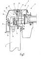
- each end face 30 of the casement 4 approximately in the central region of its longitudinal extent the braking element 17 in the form of a a bolt 31 rotatably mounted, rectangular or square fitting 32 made according to the FIGS. 4 and 5 engages in the counter element 18, that as open towards the casement 4 Guide channel 33 is formed.
- the cross-sectional dimensions of the shaped part 32 are selected in such a way that in the guide channel 33 an inhibition regarding a shift occurs such that the fitting 32 only with the application of a certain force can be moved in the guide channel 33, wherein the size of the force is chosen so that a set one Swing window opening position not automatic - also not with light wind pressure becomes.
- the guide channel 33 is in the direction of the safety gear 20 trained open, so that there Fitting 32 with a corresponding swing position of the Swing window 1 emerge and into the assembly gap 21 can occur, which is open upwards (arrow 34) is and therefore during assembly or Disassembly of the sash 4 an insertion or Removal of the molding 32 allows.
- FIGS. 1 to 6 show that in the course of the swing opening of the swing window 1, the guide rods 8 about their pivot axis 7 accordingly of the situation in Reference to swing axis 12 for guiding the fitting 32 pivoted in the guide channel 33. If the shaped piece 32 lies in the assembly niche 21, this is basically a further swing up the guide rods 3 possible, but due to the dead weight of the casement 4 practical not given. Rather occurs with further swinging the fitting 32 in the catch stop 35 one that has an overlapping edge 36 so that a further lifting of the guide rods in the cleaning position 8 and thus the sash 4 prevented is.
- FIG. 5 shows that approximately in the area of the end 37 of the guide channel 33 the inside of the braking device 16 flat, straight guideway rises (incline 38), so that by means of the molding 32 at Swinging of the sash 4 a lifting takes place.
- the braking device 16 that is to say the braking element 17 and also the counter element 18 are made of metal.
- the safety gear is a separate unit 20 executed, these made of resistant Plastic is made.
Landscapes
- Engineering & Computer Science (AREA)
- Structural Engineering (AREA)
- Mechanical Engineering (AREA)
- Architecture (AREA)
- Civil Engineering (AREA)
- Wing Frames And Configurations (AREA)
- Specific Sealing Or Ventilating Devices For Doors And Windows (AREA)
- Closing And Opening Devices For Wings, And Checks For Wings (AREA)
- Power-Operated Mechanisms For Wings (AREA)
Applications Claiming Priority (2)
| Application Number | Priority Date | Filing Date | Title |
|---|---|---|---|
| DE20206172U DE20206172U1 (de) | 2002-04-17 | 2002-04-17 | Als Schwingfenster ausgebildetes Schrägdachfenster |
| DE20206172U | 2002-04-17 |
Publications (3)
| Publication Number | Publication Date |
|---|---|
| EP1355017A2 true EP1355017A2 (fr) | 2003-10-22 |
| EP1355017A3 EP1355017A3 (fr) | 2005-02-02 |
| EP1355017B1 EP1355017B1 (fr) | 2013-05-29 |
Family
ID=7970272
Family Applications (1)
| Application Number | Title | Priority Date | Filing Date |
|---|---|---|---|
| EP03005751.7A Expired - Lifetime EP1355017B1 (fr) | 2002-04-17 | 2003-03-14 | Fenêtre de toiture avec une partie de fenêtre pivotante |
Country Status (5)
| Country | Link |
|---|---|
| EP (1) | EP1355017B1 (fr) |
| CZ (1) | CZ304260B6 (fr) |
| DE (1) | DE20206172U1 (fr) |
| HU (1) | HU227691B1 (fr) |
| PL (1) | PL213292B1 (fr) |
Family Cites Families (6)
| Publication number | Priority date | Publication date | Assignee | Title |
|---|---|---|---|---|
| GB888302A (en) * | 1959-07-09 | 1962-01-31 | Villum Benedikt Kann Rasmussen | Improvements in and relating to a window, particularly a skylight, comprising a sashtiltable around a horizontal axis, and an external covering |
| FR1268945A (fr) * | 1960-10-04 | 1961-08-04 | Fenêtre à bascule | |
| DE9404232U1 (de) * | 1994-03-12 | 1994-05-26 | Roto Frank Ag, 70771 Leinfelden-Echterdingen | Reinigungsstellungssicherung |
| DE19650190B4 (de) * | 1996-12-04 | 2005-11-17 | Roto Frank Ag | Dachfenster, insbesondere Schwingflügel-Dachfenster |
| DE19717070C1 (de) * | 1997-04-23 | 1998-11-12 | Roto Frank Ag | Dachfenster, insbesondere Schwingflügel-Dachfenster |
| DE19832262A1 (de) * | 1998-07-17 | 2000-01-20 | Roto Frank Ag | Schwingflügel-Dachfenster |
-
2002
- 2002-04-17 DE DE20206172U patent/DE20206172U1/de not_active Expired - Lifetime
-
2003
- 2003-03-14 EP EP03005751.7A patent/EP1355017B1/fr not_active Expired - Lifetime
- 2003-04-15 PL PL359699A patent/PL213292B1/pl unknown
- 2003-04-16 CZ CZ2003-1081A patent/CZ304260B6/cs not_active IP Right Cessation
- 2003-04-16 HU HU0301034A patent/HU227691B1/hu not_active IP Right Cessation
Also Published As
| Publication number | Publication date |
|---|---|
| DE20206172U1 (de) | 2002-07-18 |
| HU227691B1 (en) | 2011-11-28 |
| HUP0301034A2 (hu) | 2004-11-29 |
| CZ304260B6 (cs) | 2014-02-05 |
| CZ20031081A3 (cs) | 2003-12-17 |
| PL359699A1 (en) | 2003-10-20 |
| EP1355017B1 (fr) | 2013-05-29 |
| EP1355017A3 (fr) | 2005-02-02 |
| PL213292B1 (pl) | 2013-02-28 |
| HU0301034D0 (en) | 2003-06-28 |
Similar Documents
| Publication | Publication Date | Title |
|---|---|---|
| EP0103725B1 (fr) | Ferrure pour un battant de fenêtre, porte ou similaire, qui peut au moins être déplacée dans un plan parallèle | |
| EP2147178B1 (fr) | Agencement de charnière | |
| EP0268748B1 (fr) | Dispositif d'ouverture d'un panneau de fenêtre, porte ou similaire | |
| EP0444084B1 (fr) | Passe-plat s'inserant dans des portes et des murs | |
| DE102012202986B4 (de) | Beschlag für eine Schiebetür oder ein Schiebefenster | |
| DE3152291C2 (fr) | ||
| DE69100036T2 (de) | Beschlag fuer einen fensterfluegel eines kippfensters mit verbesserter schliessung. | |
| EP2427617B1 (fr) | Ferrure | |
| DE3619682A1 (de) | Ausstellvorrichtung fuer die fluegel von fenstern, tueren od. dgl. mit zuschlagsicherung fuer den geoeffneten fluegel | |
| DE102008028598B4 (de) | Insektenschutztür | |
| DE2157527C3 (de) | Aufstellvorrichtung für Fenster, insbeondere Schwingfenster, mit einem schwenkbaren Ausstellarm und einem Führungsbeschlag | |
| EP1355017A2 (fr) | Fenêtre de toiture avec une partie de fenêtre pivotante | |
| CH662152A5 (de) | Stellvorrichtung fuer schiebefluegel von fenstern oder tueren. | |
| EP0000915A1 (fr) | Charnière basculante pour marquises | |
| DE19906071C2 (de) | Drehbegrenzer für Dreh-Schiebe-Fenster | |
| DE102017100495A1 (de) | Kippbeschlag für einen Fensterflügel | |
| DE4419779B4 (de) | Türsicherungsvorrichtung | |
| DE2531701A1 (de) | Gelenk und eine gelenk- und drehzapfenanordnung | |
| DE202006000292U1 (de) | Ausstellvorrichtung | |
| DE3416464C2 (fr) | ||
| DE8624314U1 (de) | Ausstellvorrichtung für den wenigstens drehbaren Flügel eines Fensters, einer Tür od.dgl. | |
| DE2631453A1 (de) | Beschlag fuer dachfenster | |
| CH655970A5 (en) | Dormer window | |
| DE102011117033B4 (de) | Hubtor für eine Toröffnung in einer Wand | |
| EP1582672B1 (fr) | Renvoi d'angle pour ventilation réglable et limitation d'ouverture dans une condamnation centrale |
Legal Events
| Date | Code | Title | Description |
|---|---|---|---|
| PUAI | Public reference made under article 153(3) epc to a published international application that has entered the european phase |
Free format text: ORIGINAL CODE: 0009012 |
|
| AK | Designated contracting states |
Kind code of ref document: A2 Designated state(s): AT BE BG CH CY CZ DE DK EE ES FI FR GB GR HU IE IT LI LU MC NL PT RO SE SI SK TR |
|
| AX | Request for extension of the european patent |
Extension state: AL LT LV MK |
|
| PUAL | Search report despatched |
Free format text: ORIGINAL CODE: 0009013 |
|
| AK | Designated contracting states |
Kind code of ref document: A3 Designated state(s): AT BE BG CH CY CZ DE DK EE ES FI FR GB GR HU IE IT LI LU MC NL PT RO SE SI SK TR |
|
| AX | Request for extension of the european patent |
Extension state: AL LT LV MK |
|
| 17P | Request for examination filed |
Effective date: 20050607 |
|
| AKX | Designation fees paid |
Designated state(s): DE DK ES FR GB |
|
| 17Q | First examination report despatched |
Effective date: 20090304 |
|
| GRAP | Despatch of communication of intention to grant a patent |
Free format text: ORIGINAL CODE: EPIDOSNIGR1 |
|
| RIC1 | Information provided on ipc code assigned before grant |
Ipc: E04D 13/035 20060101AFI20121204BHEP Ipc: E05D 15/44 20060101ALI20121204BHEP Ipc: E05D 7/086 20060101ALI20121204BHEP |
|
| GRAS | Grant fee paid |
Free format text: ORIGINAL CODE: EPIDOSNIGR3 |
|
| GRAA | (expected) grant |
Free format text: ORIGINAL CODE: 0009210 |
|
| AK | Designated contracting states |
Kind code of ref document: B1 Designated state(s): DE DK ES FR GB |
|
| REG | Reference to a national code |
Ref country code: GB Ref legal event code: FG4D Free format text: NOT ENGLISH |
|
| REG | Reference to a national code |
Ref country code: DE Ref legal event code: R096 Ref document number: 50314802 Country of ref document: DE Effective date: 20130725 |
|
| PG25 | Lapsed in a contracting state [announced via postgrant information from national office to epo] |
Ref country code: ES Free format text: LAPSE BECAUSE OF FAILURE TO SUBMIT A TRANSLATION OF THE DESCRIPTION OR TO PAY THE FEE WITHIN THE PRESCRIBED TIME-LIMIT Effective date: 20130909 |
|
| PG25 | Lapsed in a contracting state [announced via postgrant information from national office to epo] |
Ref country code: DK Free format text: LAPSE BECAUSE OF FAILURE TO SUBMIT A TRANSLATION OF THE DESCRIPTION OR TO PAY THE FEE WITHIN THE PRESCRIBED TIME-LIMIT Effective date: 20130529 |
|
| PLBE | No opposition filed within time limit |
Free format text: ORIGINAL CODE: 0009261 |
|
| STAA | Information on the status of an ep patent application or granted ep patent |
Free format text: STATUS: NO OPPOSITION FILED WITHIN TIME LIMIT |
|
| 26N | No opposition filed |
Effective date: 20140303 |
|
| REG | Reference to a national code |
Ref country code: DE Ref legal event code: R097 Ref document number: 50314802 Country of ref document: DE Effective date: 20140303 |
|
| REG | Reference to a national code |
Ref country code: FR Ref legal event code: PLFP Year of fee payment: 14 |
|
| PGFP | Annual fee paid to national office [announced via postgrant information from national office to epo] |
Ref country code: GB Payment date: 20160322 Year of fee payment: 14 |
|
| REG | Reference to a national code |
Ref country code: FR Ref legal event code: PLFP Year of fee payment: 15 |
|
| GBPC | Gb: european patent ceased through non-payment of renewal fee |
Effective date: 20170314 |
|
| PG25 | Lapsed in a contracting state [announced via postgrant information from national office to epo] |
Ref country code: GB Free format text: LAPSE BECAUSE OF NON-PAYMENT OF DUE FEES Effective date: 20170314 |
|
| REG | Reference to a national code |
Ref country code: FR Ref legal event code: PLFP Year of fee payment: 16 |
|
| PGFP | Annual fee paid to national office [announced via postgrant information from national office to epo] |
Ref country code: DE Payment date: 20220322 Year of fee payment: 20 |
|
| PGFP | Annual fee paid to national office [announced via postgrant information from national office to epo] |
Ref country code: FR Payment date: 20220323 Year of fee payment: 20 |
|
| REG | Reference to a national code |
Ref country code: DE Ref legal event code: R071 Ref document number: 50314802 Country of ref document: DE |