EP1355018A2 - Glissière de guidage pour une fenêtre de toit - Google Patents
Glissière de guidage pour une fenêtre de toit Download PDFInfo
- Publication number
- EP1355018A2 EP1355018A2 EP03005752A EP03005752A EP1355018A2 EP 1355018 A2 EP1355018 A2 EP 1355018A2 EP 03005752 A EP03005752 A EP 03005752A EP 03005752 A EP03005752 A EP 03005752A EP 1355018 A2 EP1355018 A2 EP 1355018A2
- Authority
- EP
- European Patent Office
- Prior art keywords
- sliding
- sliding guide
- guide device
- sliding surface
- guide piece
- Prior art date
- Legal status (The legal status is an assumption and is not a legal conclusion. Google has not performed a legal analysis and makes no representation as to the accuracy of the status listed.)
- Granted
Links
Images




Classifications
-
- E—FIXED CONSTRUCTIONS
- E04—BUILDING
- E04D—ROOF COVERINGS; SKY-LIGHTS; GUTTERS; ROOF-WORKING TOOLS
- E04D13/00—Special arrangements or devices in connection with roof coverings; Protection against birds; Roof drainage ; Sky-lights
- E04D13/03—Sky-lights; Domes; Ventilating sky-lights
- E04D13/035—Sky-lights; Domes; Ventilating sky-lights characterised by having movable parts
- E04D13/0351—Sky-lights; Domes; Ventilating sky-lights characterised by having movable parts the parts pivoting about a fixed axis
- E04D13/0354—Sky-lights; Domes; Ventilating sky-lights characterised by having movable parts the parts pivoting about a fixed axis the parts being flat
-
- E—FIXED CONSTRUCTIONS
- E04—BUILDING
- E04D—ROOF COVERINGS; SKY-LIGHTS; GUTTERS; ROOF-WORKING TOOLS
- E04D13/00—Special arrangements or devices in connection with roof coverings; Protection against birds; Roof drainage ; Sky-lights
- E04D13/03—Sky-lights; Domes; Ventilating sky-lights
- E04D13/035—Sky-lights; Domes; Ventilating sky-lights characterised by having movable parts
- E04D13/0357—Sky-lights; Domes; Ventilating sky-lights characterised by having movable parts the parts pivoting about an axis supported on a hinged frame or arms
Definitions
- the invention relates to a sliding guide device for the inhibition of the position of a casement a roof window, in particular swing and / or Folding roof windows.
- Sliding guide devices of the aforementioned kind consist of one on the casement of a roof window fixed guide piece, the along a on the frame of the Window fixed guide rail relocatable is. Such is preferably located Sliding guide device on both sides of the Roof windows.
- the sliding guide has the task, the swinging movement of a roof window to control.
- the sash is over so-called guide rods attached to the frame.
- On both sides of the roof window is one guide rod each is provided, the lower one Swiveling ends with the sash and the upper ends of which can be pivoted with the frame are connected.
- the guide rods In the course of an opening movement can the guide rods relative to the frame pivot and allow the To raise the swing axis so that an operator There is space under the window that opens.
- the sliding guide device guides the casement up to a cleaning position in which the glass outside can be cleaned from the room.
- the known sliding guide devices have the Disadvantage that, for example, depending on the Roof pitch and / or due to wind pressure- a secure definition of the open window window sash not possible. There are unintentional ones Position adjustments.
- the invention has for its object the mentioned Eliminate disadvantages.
- a on the frame definable body that has a first sliding surface a sliding guide channel for one on the casement has fixable guide piece and with a by means of an adjustment device on Main body held channel element, the second Has sliding surface that with the first sliding surface a clamping passage adjustable in clamping distance forms for the guide piece.
- the on Sash frame lockable guide piece and the the slide guide channel assigned to the frame can be a roof window that works as a swing and / or Folding roof windows are designed can, easily with a sliding guide device equip or retrofit. Since the invention Design has a clamping passage, the Clamping distance is adjustable, can be ensured that the guide piece is only being brought up along a selectively large displacement force the sliding guide channel is movable.
- the guide piece is elastic, in particular inherently elastic, designed in relation to the clamping effect is.
- the elasticity or self-elasticity of the clamping piece leads to the fact that Guide piece held securely in the slide guide channel but still - with appropriate effort on the operating handle of the casement can be, for example, another Bring open position or the window close or in a cleaning position spend.
- the adjustment device as a wedge device is trained.
- wedge device is one Understand construction where a fixed Element and a displaceable element are provided are, with the displaceable element under Use at least one wedge-shaped slope opposite the fixed element. Due to the formation of wedges, a shift leads to change the distance between the two parts. in the present case to a change in the clamping distance of the sliding guide channel in which the guide piece slides. It is possible that only part has a bevel and the other part does not is wedge-shaped. Still is due a wedge formation ensures adjustability. Alternatively, however, can also be provided be that both parts have wedge bevels. Also this is - possibly even reinforced - a change ensures a change in distance.
- the adjustment device provided with an adjustment grid.
- a shift can be done by the adjustment grid carry out in defined steps.
- An adjustment marking scale can be preferred be provided, which shows in which The clamping passage is in the set state.
- the adjustment mark scale notes on the sloping roof. With steeper ones Roofs, for example, is one of the adjustment mark scales removable removable clamp to adjust than with less steeply pitched roofs.
- the Determination of the wedge device by means of at least an elongated screw connection.
- For setting the clamping passage is then only necessary loosen the screw connection so far that a displacement of the channel element relative to Basic body is possible. Is the desired location set, the screw connection is tightened and thus the clamping distance of the clamping passage fixed.
- the first sliding surface is preferably on the top a base plate of the base body.
- a mounting rail lies at a distance from this base plate opposite, on the underside of which supports the channel element.
- the mounting rail is preferably connected to the base body via a web.
- the base body, web and mounting rail preferably form an open U in which the guide piece protrudes.
- the wedge or the wedges can be arranged such that a displacement of the channel element across, especially at right angles to Longitudinal extension of the mounting rail to change the clamping distance leads.
- the first sliding surface runs parallel to second sliding surface.
- the length of the first sliding surface is greater formed as the length of the second sliding surface is.
- the length of the second sliding surface projecting area of the first Design the sliding surface in an arc shape, that is, the guide piece moves during normal Opening movement along the straight clamping passage and hits - in the course of the further opening movement - on the rising arch beyond the Clamping passage, then - when reaching the cleaning position - after passing through the arcuate area to be at a higher level and finally up to to reach the scope of a fan element, that secures the cleaning position.
- the invention further relates to a roof window, that with at least one sliding guide device provided in the training described above is.
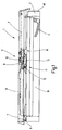
- Figure 1 shows a roof window 1, the one Frame 2 and a sash 3 has.
- the casement is with an operating handle 4 Mistake.
- the roof window 1 is a pure swing window 5, although it has guide rods 6, each with one end 7 by means of a pivot axis 8 on the frame 2 set are and each with its other end 9 by means of a swing axis 19 carry the sash 3.
- the invention is not based on such Swing window limited, but it can for example also with hinged and / or swinging pitched roof windows be used.
- each vertical spar of the roof window 1 has a corresponding one Design with preferably one each Sliding guide device 11.
- the sliding guide device 11 has a sliding guide channel 12 on, which is fixed to the frame 2 is arranged.
- a Guide piece 13 On the sash 3 is a Guide piece 13 arranged, depending from the position of the casement 3- in the sliding guide channel 12 is clamped or picked up is located outside the sliding guide channel 12.
- the sliding guide device 11 approximately in the middle the vertical extent of the roof window 1, wherein a part is attached to the frame 2 and there is another part on the sash 3.
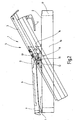
- Figures 4 to 6 illustrate the position of the Guide piece 13 depending on the position of the sash 3. These figures are shown below discussed in more detail.
- the closed in particular shows the locked position of the casement 3, lies the guide piece 13 in the end region 15 of the Slideway 12, which is rectilinear is and parallel to the longitudinal extension of the vertical spar 16 of the frame 2 runs.
- the swing axis 10 lies above the guide piece 13 and is also closer to the lower horizontal beam 17 of the Frame 2 arranged as the guide piece 13.
- the guide piece 13 shifts in the direction to the other end region 18 of the sliding guide channel 12, due to the inclination of the casement 3 relative to the plane of the frame 2 the guide rod 6 is raised.
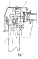
- Figure 7 illustrates the design of the guide piece 13. This has one on the sash 3 attached bolt 23 on which a cross-section square guide element 24 rotatable the pin axis 25 supports.
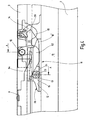
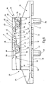
- FIGS 8 and 9 illustrate the construction the slide guide device 11 with respect to their Slideway 12.
- the slideway 11 has a base body 26, which is a base plate 27 has.
- the bottom of the base plate 28 is with two spaced apart Holding projections 29 provided in corresponding Receiving holes of the frame 2 inserted become.
- the mounting holes 30 are provided with countersink sections, which the Pick up screw heads.
- a first sliding surface 32 is formed, on which the guide piece 13 can slide.
- a side edge region 33 extends from the Base plate 26 is a web 34, which is rectangular to the first sliding surface 32 and in its Longitudinal extension is shorter than the sliding surface 32, so that it stands out on both sides of it Area 35 and an outstanding area 36 of the Forms sliding surface 32.
- the web 34 goes into one Mounting rail 37 over which projects such that them together with the web 34 and the base plate 27 - seen in cross section - forms an open U.
- the Bottom side 38 of the mounting rail 37 is designed such that - following the outstanding Area 26 initially rises in a straight line, that is, their distance from the top 31 of the base plate 27 steadily increases to a level 39, the protrudes towards the top 31 and accordingly the distance to the first sliding surface 32 reduced.
- the web 34 has two spaced apart Threaded bores 46, one in each Locking screw 47 is screwed in.
- Each of the Locking screws 47 pass through an elongated hole 48, which is formed on a channel element 49, the has approximately the same length as the web 34 and itself with a contact surface 50 on the underside 38 the mounting rail 37 supports. Training the Contact surface 50 is made such that its course the course of the bottom 38 corresponds to that means it is in Figure 9 from left to right seen - initially a straight rising area 51 provided that goes into a stage 52 and it follows an increasing level 52 rectilinear area 53.
- a mark 56 on one Front side 57 of the channel element 49 corresponds with one of the marks 45 of the mounting rail 37 and thereby shows the relative position of the channel element 49 to the mounting rail 37.
- the end face opposite the end face 57 58 bears against the web 34 and serves an additional support for the channel element 49.
- the underside opposite the contact surface 50 59 of the channel element 49 forms a second one Sliding surface 60 for the guide piece 13, the Arrangement is made such that when Underside 38 and contact surface 50 the second sliding surface 60 runs parallel to the first sliding surface 32. Thus, the two sliding surfaces 32 and 60 from the sliding guide channel 12.
- the Guide element 24 made of a material, preferably a plastic material with a certain inherent elasticity exists, so that of the sliding surfaces 32 and 60 applied clamp pressure intercepted is, that is, a displacement of the guide piece 13 along the sliding guide channel 12 with the corresponding Force is possible.
- the components of the device shown in Figures 8 and 9 are preferably made of metal and therefore have a lower material elasticity than that of the Guide piece 13.
- the inclined surfaces from the bottom 38 and contact surface 50 lead to an adjustment device 63, which is designed as a wedge device 64 is.
- By moving the channel element 49 relatively to the mounting rail 37 is due to the wedge effect the clamping distance 61 between the first sliding surface 32 and the second sliding surface 60, wherein the adjustment catch 41 a gradual adjustment allows. Is the desired setting of the channel element 49, this is done by Tighten the locking screws 47 and thus fixes the desired setting.
- the guide piece 13 is in the course of the opening movement of the casement 3 through the sliding guide channel 12 moves, the straight and parallel runs to the level of the frame 2. Leaves the guide piece 13 in the course of taking one Cleaning position the sliding guide channel 12, so slides it on an arcuate region 36 and then enters the above already mentioned, on the frame 2 catch element 14 a.
Landscapes
- Engineering & Computer Science (AREA)
- Architecture (AREA)
- Civil Engineering (AREA)
- Structural Engineering (AREA)
- Wing Frames And Configurations (AREA)
- Closing And Opening Devices For Wings, And Checks For Wings (AREA)
- Projection Apparatus (AREA)
Applications Claiming Priority (2)
| Application Number | Priority Date | Filing Date | Title |
|---|---|---|---|
| DE10217531A DE10217531B4 (de) | 2002-04-17 | 2002-04-17 | Gleitführungsvorrichtung für ein Wohndachfenster sowie Wohndachfenster mit Gleitführungsvorrichtung |
| DE10217531 | 2002-04-17 |
Publications (3)
| Publication Number | Publication Date |
|---|---|
| EP1355018A2 true EP1355018A2 (fr) | 2003-10-22 |
| EP1355018A3 EP1355018A3 (fr) | 2005-02-09 |
| EP1355018B1 EP1355018B1 (fr) | 2017-06-28 |
Family
ID=28458926
Family Applications (1)
| Application Number | Title | Priority Date | Filing Date |
|---|---|---|---|
| EP03005752.5A Expired - Lifetime EP1355018B1 (fr) | 2002-04-17 | 2003-03-14 | Glissière de guidage pour une fenêtre de toit |
Country Status (7)
| Country | Link |
|---|---|
| EP (1) | EP1355018B1 (fr) |
| CZ (1) | CZ300986B6 (fr) |
| DE (1) | DE10217531B4 (fr) |
| DK (1) | DK1355018T3 (fr) |
| ES (1) | ES2640463T3 (fr) |
| HU (1) | HU227689B1 (fr) |
| PL (1) | PL202913B1 (fr) |
Cited By (2)
| Publication number | Priority date | Publication date | Assignee | Title |
|---|---|---|---|---|
| EP1691000A1 (fr) * | 2005-01-21 | 2006-08-16 | Aug. Winkhaus GmbH & Co. KG | Fenêtre de toit basculante pivotante |
| DE102009050875A1 (de) * | 2009-10-27 | 2011-04-28 | Niehaus, Joachim, Dipl.-Ing. | Vorrichtung zum Öffnen und Schließen von Fenstern an Wohnwagen, Wohnmobilen und dergleichen |
Citations (1)
| Publication number | Priority date | Publication date | Assignee | Title |
|---|---|---|---|---|
| PL177697B1 (pl) | 1994-07-13 | 2000-01-31 | Roto Frank Ag | Okno dachowe z ustalaczem |
Family Cites Families (2)
| Publication number | Priority date | Publication date | Assignee | Title |
|---|---|---|---|---|
| DE9406929U1 (de) * | 1994-04-26 | 1994-06-16 | Roto Frank Ag, 70771 Leinfelden-Echterdingen | Dachfenster |
| DE19717070C1 (de) * | 1997-04-23 | 1998-11-12 | Roto Frank Ag | Dachfenster, insbesondere Schwingflügel-Dachfenster |
-
2002
- 2002-04-17 DE DE10217531A patent/DE10217531B4/de not_active Expired - Lifetime
-
2003
- 2003-03-14 EP EP03005752.5A patent/EP1355018B1/fr not_active Expired - Lifetime
- 2003-03-14 DK DK03005752.5T patent/DK1355018T3/da active
- 2003-03-14 ES ES03005752.5T patent/ES2640463T3/es not_active Expired - Lifetime
- 2003-04-15 PL PL359698A patent/PL202913B1/pl unknown
- 2003-04-16 HU HU0301035A patent/HU227689B1/hu not_active IP Right Cessation
- 2003-04-16 CZ CZ20031079A patent/CZ300986B6/cs not_active IP Right Cessation
Patent Citations (1)
| Publication number | Priority date | Publication date | Assignee | Title |
|---|---|---|---|---|
| PL177697B1 (pl) | 1994-07-13 | 2000-01-31 | Roto Frank Ag | Okno dachowe z ustalaczem |
Cited By (3)
| Publication number | Priority date | Publication date | Assignee | Title |
|---|---|---|---|---|
| EP1691000A1 (fr) * | 2005-01-21 | 2006-08-16 | Aug. Winkhaus GmbH & Co. KG | Fenêtre de toit basculante pivotante |
| DE102009050875A1 (de) * | 2009-10-27 | 2011-04-28 | Niehaus, Joachim, Dipl.-Ing. | Vorrichtung zum Öffnen und Schließen von Fenstern an Wohnwagen, Wohnmobilen und dergleichen |
| DE102009050875B4 (de) * | 2009-10-27 | 2014-08-14 | Joachim NieHaus | Vorrichtung zum Öffnen und Schließen von Fenstern an Wohnwagen, Wohnmobilen und dergleichen |
Also Published As
| Publication number | Publication date |
|---|---|
| ES2640463T3 (es) | 2017-11-03 |
| DE10217531A1 (de) | 2003-11-13 |
| PL359698A1 (en) | 2003-10-20 |
| CZ20031079A3 (cs) | 2003-12-17 |
| EP1355018A3 (fr) | 2005-02-09 |
| EP1355018B1 (fr) | 2017-06-28 |
| CZ300986B6 (cs) | 2009-10-07 |
| HUP0301035A2 (hu) | 2004-11-29 |
| DK1355018T3 (da) | 2017-10-02 |
| PL202913B1 (pl) | 2009-08-31 |
| HU227689B1 (en) | 2011-11-28 |
| DE10217531B4 (de) | 2005-08-11 |
Similar Documents
| Publication | Publication Date | Title |
|---|---|---|
| DE2547319C3 (de) | Verriegelung für Fenster oder Türen | |
| DE3441497C2 (fr) | ||
| EP0065109B1 (fr) | Charnière | |
| AT519903B1 (de) | Schiene zur Führung eines Schlittens einer Möbeltüre | |
| EP0010144B1 (fr) | Ferrure d'articulation pour fenêtres, portes ou analogues | |
| EP0005764B2 (fr) | Porte ou fenêtre coulissante et basculante | |
| DE4404653A1 (de) | Klemmprofil, insbesondere für eine Glasscheibe | |
| EP0276678B1 (fr) | Ferrure pour porte ou fenêtre au moins pivotantes | |
| DE3904210C2 (fr) | ||
| DE3429699C2 (de) | Fehlbedienungssperre für Treibstangenbeschläge | |
| DE3916216C2 (fr) | ||
| DE9113522U1 (de) | Beschlag zur Befestigung in einer beidseitig hinterschnittenen Profilnut | |
| DE2211523B2 (de) | Schließstück für Metall- oder Kunststoff-Fenster oder -Türen | |
| EP1355018B1 (fr) | Glissière de guidage pour une fenêtre de toit | |
| AT15365U1 (de) | Verglasungssystem | |
| DE3025885A1 (de) | Beschlag von kipp-schwenk-fluegeln von fenstern, tueren o.dgl. | |
| EP0247281A1 (fr) | Dispositif de fermeture pour empêcher l'ouverture non autorisée de battants de portes, fenêtres ou similaires | |
| DE102007025857A1 (de) | Gelenkband für Türen oder Fenster | |
| DE2729394A1 (de) | Verriegelungseinrichtung fuer fenster, tueren o.dgl. | |
| DE4032604C2 (de) | Schiebetüranlage mit wenigstens einem schieb- und schwenkbaren Türflügel | |
| DE2614810C3 (de) | Halte- und Führungsvorrichtung für Möbelschiebetüren | |
| DE2064047A1 (de) | Vorrichtung zur Feineinstellung von Dreh Kipp Fenstern | |
| CH648377A5 (en) | Window or door | |
| EP1001123B1 (fr) | Penture de porte ou de fenêtre | |
| DE1708443A1 (de) | Beschlag fuer Kipp-Schwenkfluegel von Fenstern |
Legal Events
| Date | Code | Title | Description |
|---|---|---|---|
| PUAI | Public reference made under article 153(3) epc to a published international application that has entered the european phase |
Free format text: ORIGINAL CODE: 0009012 |
|
| AK | Designated contracting states |
Kind code of ref document: A2 Designated state(s): AT BE BG CH CY CZ DE DK EE ES FI FR GB GR HU IE IT LI LU MC NL PT RO SE SI SK TR |
|
| AX | Request for extension of the european patent |
Extension state: AL LT LV MK |
|
| PUAL | Search report despatched |
Free format text: ORIGINAL CODE: 0009013 |
|
| AK | Designated contracting states |
Kind code of ref document: A3 Designated state(s): AT BE BG CH CY CZ DE DK EE ES FI FR GB GR HU IE IT LI LU MC NL PT RO SE SI SK TR |
|
| AX | Request for extension of the european patent |
Extension state: AL LT LV MK |
|
| 17P | Request for examination filed |
Effective date: 20050607 |
|
| AKX | Designation fees paid |
Designated state(s): DE DK ES FR GB |
|
| 17Q | First examination report despatched |
Effective date: 20090304 |
|
| TPAC | Observations filed by third parties |
Free format text: ORIGINAL CODE: EPIDOSNTIPA |
|
| GRAP | Despatch of communication of intention to grant a patent |
Free format text: ORIGINAL CODE: EPIDOSNIGR1 |
|
| INTG | Intention to grant announced |
Effective date: 20170116 |
|
| GRAS | Grant fee paid |
Free format text: ORIGINAL CODE: EPIDOSNIGR3 |
|
| GRAA | (expected) grant |
Free format text: ORIGINAL CODE: 0009210 |
|
| AK | Designated contracting states |
Kind code of ref document: B1 Designated state(s): DE DK ES FR GB |
|
| REG | Reference to a national code |
Ref country code: GB Ref legal event code: FG4D Free format text: NOT ENGLISH |
|
| REG | Reference to a national code |
Ref country code: DE Ref legal event code: R096 Ref document number: 50315670 Country of ref document: DE |
|
| REG | Reference to a national code |
Ref country code: DK Ref legal event code: T3 Effective date: 20170928 |
|
| REG | Reference to a national code |
Ref country code: ES Ref legal event code: FG2A Ref document number: 2640463 Country of ref document: ES Kind code of ref document: T3 Effective date: 20171103 |
|
| REG | Reference to a national code |
Ref country code: FR Ref legal event code: PLFP Year of fee payment: 16 |
|
| REG | Reference to a national code |
Ref country code: DE Ref legal event code: R097 Ref document number: 50315670 Country of ref document: DE |
|
| PLBE | No opposition filed within time limit |
Free format text: ORIGINAL CODE: 0009261 |
|
| STAA | Information on the status of an ep patent application or granted ep patent |
Free format text: STATUS: NO OPPOSITION FILED WITHIN TIME LIMIT |
|
| 26N | No opposition filed |
Effective date: 20180329 |
|
| PGFP | Annual fee paid to national office [announced via postgrant information from national office to epo] |
Ref country code: GB Payment date: 20220324 Year of fee payment: 20 Ref country code: DK Payment date: 20220322 Year of fee payment: 20 Ref country code: DE Payment date: 20220322 Year of fee payment: 20 |
|
| PGFP | Annual fee paid to national office [announced via postgrant information from national office to epo] |
Ref country code: FR Payment date: 20220322 Year of fee payment: 20 |
|
| PGFP | Annual fee paid to national office [announced via postgrant information from national office to epo] |
Ref country code: ES Payment date: 20220420 Year of fee payment: 20 |
|
| REG | Reference to a national code |
Ref country code: DE Ref legal event code: R071 Ref document number: 50315670 Country of ref document: DE |
|
| REG | Reference to a national code |
Ref country code: DK Ref legal event code: EUP Expiry date: 20230314 |
|
| REG | Reference to a national code |
Ref country code: GB Ref legal event code: PE20 Expiry date: 20230313 |
|
| REG | Reference to a national code |
Ref country code: ES Ref legal event code: FD2A Effective date: 20230503 |
|
| PG25 | Lapsed in a contracting state [announced via postgrant information from national office to epo] |
Ref country code: GB Free format text: LAPSE BECAUSE OF EXPIRATION OF PROTECTION Effective date: 20230313 |
|
| PG25 | Lapsed in a contracting state [announced via postgrant information from national office to epo] |
Ref country code: ES Free format text: LAPSE BECAUSE OF EXPIRATION OF PROTECTION Effective date: 20230315 |