EP1355838B2 - Dispositif et procede de transport de pieces - Google Patents
Dispositif et procede de transport de pieces Download PDFInfo
- Publication number
- EP1355838B2 EP1355838B2 EP02706640A EP02706640A EP1355838B2 EP 1355838 B2 EP1355838 B2 EP 1355838B2 EP 02706640 A EP02706640 A EP 02706640A EP 02706640 A EP02706640 A EP 02706640A EP 1355838 B2 EP1355838 B2 EP 1355838B2
- Authority
- EP
- European Patent Office
- Prior art keywords
- negative pressure
- compressed air
- gap
- conveyor belt
- work pieces
- Prior art date
- Legal status (The legal status is an assumption and is not a legal conclusion. Google has not performed a legal analysis and makes no representation as to the accuracy of the status listed.)
- Expired - Lifetime
Links
Images


Classifications
-
- B—PERFORMING OPERATIONS; TRANSPORTING
- B65—CONVEYING; PACKING; STORING; HANDLING THIN OR FILAMENTARY MATERIAL
- B65G—TRANSPORT OR STORAGE DEVICES, e.g. CONVEYORS FOR LOADING OR TIPPING, SHOP CONVEYOR SYSTEMS OR PNEUMATIC TUBE CONVEYORS
- B65G21/00—Supporting or protective framework or housings for endless load-carriers or traction elements of belt or chain conveyors
- B65G21/20—Means incorporated in, or attached to, framework or housings for guiding load-carriers, traction elements or loads supported on moving surfaces
- B65G21/2027—Suction retaining means
- B65G21/2036—Suction retaining means for retaining the load on the load-carrying surface
-
- B—PERFORMING OPERATIONS; TRANSPORTING
- B65—CONVEYING; PACKING; STORING; HANDLING THIN OR FILAMENTARY MATERIAL
- B65G—TRANSPORT OR STORAGE DEVICES, e.g. CONVEYORS FOR LOADING OR TIPPING, SHOP CONVEYOR SYSTEMS OR PNEUMATIC TUBE CONVEYORS
- B65G47/00—Article or material-handling devices associated with conveyors; Methods employing such devices
- B65G47/74—Feeding, transfer, or discharging devices of particular kinds or types
- B65G47/90—Devices for picking-up and depositing articles or materials
- B65G47/91—Devices for picking-up and depositing articles or materials incorporating pneumatic, e.g. suction, grippers
- B65G47/911—Devices for picking-up and depositing articles or materials incorporating pneumatic, e.g. suction, grippers with air blasts producing partial vacuum
Definitions
- the invention relates to a device and a method for the transport of workpieces.
- each suction nozzle is associated with a particular negative pressure generating device.
- the vacuum generator can be turned on individually or in groups.
- vacuum generating devices are turned off.
- the suction nozzles are arranged here at a small distance to the transport side of the workpiece. The distance between the transport side of the workpieces and the suction nozzles is chosen so small that only a small amount of false air is sucked through the two edges of the workpiece remaining opening slots. It is almost a stationary negative pressure forms.
- the known device is constructed relatively expensive. There are a variety of negative pressure generating devices to provide. This requires a relatively large amount of space.
- the known device is not particularly compact. Because of the formation of a stationary negative pressure, large workpieces with a higher force per unit area are attracted to the conveyor belt than small workpieces. Depending on the size of the workpiece, the drive motor must be driven with a different power, so that the conveying speed can be kept constant. The application of a static negative pressure also causes it to break down more slowly during shutdown for large workpieces than for small workpieces. Depending on the size and weight of the adhering workpiece, the discharge takes place only after a different length of time has elapsed after switching off the vacuum generating devices. By means of the known device, a targeted discharge of workpieces is not possible.
- the suction nozzles are arranged between two parallel arranged conveyor belts. They are offset from a transport side of the workpieces by a small distance, so that a narrow gap between the transport side of the workpiece and the opening edge of the suction nozzle is formed.
- transverse webs are provided which divide the suction surface between the conveyor belts into rectangular suction zones.
- the object of the invention is to eliminate the disadvantages of the prior art.
- a device for the suspended transport of non-magnetic Maschinenstükken be specified, which is simple and inexpensive to produce.
- Another object of the invention is to provide a device and a method with which a pinpoint ejection of workpieces of different sizes and different weights is equally possible.
- a dynamic negative pressure is a negative pressure understood, which forms according to the Venturi principle in consequence of a flow.
- the flow is directed from the aeration device to the suction openings.
- Condition for the setting of a dynamic negative pressure is that per unit time, a sufficiently high volume flow through the ventilation device is supplied to the gap and sucked through the suction again. It then forms in the gap from a sufficiently high flow rate for the generation of the negative pressure.
- the size of the negative pressure results from the Bernoulli equation. Typical flow velocities here are between 60 and 80 m / sec.
- the design of the dynamic negative pressure provided according to the invention has the advantage that workpieces, regardless of their size, are always held on the conveyor belt with the same specific force per unit area. Accurate ejection is possible regardless of the size of the workpiece. The workpieces can always be transported at the same speed without regulating the power of a drive unit.
- the suction openings are provided on a wall facing the workpieces of a substantially parallel to the transport direction of the workpieces extending vacuum channel.
- a common vacuum channel eliminates the need to provide each of the suction with a special negative pressure generating device.
- the device can be operated with a single vacuum generating device connected to the vacuum channel. It can be made compact.
- the provision of a common vacuum channel also creates constructive freedom, which can be used to receive means for accurate discharge of the workpieces.
- the suction openings are formed by suction nozzles received in the wall. That allows the To equip device according to requirements with suction of a suitable Ansaugqueritess.
- the means for aeration on the side facing the workpieces of the holding device in a regular arrangement on ventilation openings, so that sets over the entire length of the gap, a substantially uniform dynamic negative pressure.
- the means for ventilation ensures that workpieces are held at any time with the same force on the conveyor belt regardless of their size.
- the ventilation openings can be arranged on the workpiece-facing wall of the vacuum channel.
- each of the ventilation openings forms the end of a ventilation duct which extends through the vacuum duct and which can be connected to a ventilation duct.
- the ventilation duct may be in communication with the environment for ventilation, but it may also be subjected to a slight overpressure.
- a device for controlling and / or regulating the dynamic negative pressure can be a device for controlling and / or regulating a negative pressure source which acts on the negative pressure channel.
- the device e.g. the speed of a vacuum source used as a vacuum source to be changed.
- a means for controlling the passing through the ventilation duct air quantity This makes the device particularly universal. It can e.g. By adjusting an air panel easily be adapted to the respective requirements profile.
- the vacuum channel is constantly subjected to a predetermined negative pressure, which is so dimensioned that quickly builds up the required flow velocity when creating a workpiece to the conveyor belt in the gap.
- a device for selectively generating a dynamic negative pressure interrupting compressed air surge can be provided.
- the device for generating a blast of compressed air may be provided along a predetermined region of the holding device.
- the predetermined area may be a discharge zone of the workpieces.
- the blast of compressed air from the vacuum channel is directed through the suction to the gap.
- the dynamic negative pressure can not only be interrupted for discharging the workpieces, but it can additionally blown air into the predetermined region of the gap and thus a quick ejection of the workpieces can be achieved. If air continues to be sucked through the suction openings when the compressed-air pulse is generated in the predetermined region, the amount of air supplied per unit of time per unit of air pressure must be greater than the volume of air extracted through the suction openings.
- the device has coaxial with the suction openings arranged compressed air nozzles.
- the compressed air nozzles can be moved back and forth axially against the suction openings.
- the suction openings can be closed by means of the compressed-air nozzles. In the closed state, no air can be sucked out of the gap into the vacuum channel through the suction openings.
- adjustable pistons can be used instead of compressed air nozzles with compressed air, which selectively close the suction openings.
- each intake opening is assigned in each case a ventilation opening and possibly a compressed-air nozzle.
- the ratio of the number of suction ports to the number of ventilation holes and possibly the compressed air nozzles is chosen differently.
- the suction openings and the ventilation openings can alternately be arranged one behind the other in the longitudinal extent of the holding device. The aforementioned features contribute to a simplified construction. The device can thus be manufactured inexpensively.
- the compressed air nozzles can be pressurized with compressed air.
- a control device known from the prior art can be provided.
- magnets are accommodated in the holding device, preferably electrically switchable, so that magnetic workpieces can be optionally retained by the magnetic field adhering to the conveyor belt.
- the vacuum channel is disposed between the magnets.
- a means for ventilating the gap is provided, so that the workpiece is held by a forming in the gap dynamic negative pressure on the conveyor belt.
- the means for aeration along the holding device in a regular arrangement on ventilation openings, so that sets over the entire length of the gap, a substantially uniform dynamic negative pressure. This ensures that at all points along the gap, the workpieces are always tightened with the same force on the conveyor belt.
- the dynamic negative pressure is interrupted by a compressed air blast directed into the gap for discharging the workpieces.
- the proposed method causes a sudden collapse of the dynamic negative pressure. On the conveyor belt adhering workpieces can thus be accurately dropped.
- the compressed air blast can be directed from a vacuum channel through the suction to the gap. The provision of such a vacuum channel further contributes to the fact that a device suitable for carrying out the method can be constructed in a compact and simple manner.
- the dynamic negative pressure may also be controlled and / or regulated by a means for ventilating the gap.
- a means for ventilating the gap To set a predetermined dynamic negative pressure so the gap a predetermined amount of air can be supplied.
- the device for ventilation may have ventilation openings on the wall of the vacuum duct facing the workpieces. Each ventilation opening may form the end of a ventilation duct which extends through the vacuum duct. The ventilation openings are expediently connected to a ventilation duct.
- the dynamic negative pressure can be adjusted by means of a control and / or regulation device. It may be a device with which the ventilation of the gap is controlled and / or regulated.
- the compressed air nozzles are moved axially when exposed to compressed air in the direction of the suction.
- the suction openings can be closed with compressed air, preferably by means of the compressed-air nozzles.
- the blast of compressed air is preferably generated in a predetermined group of successive intake ports. This makes it possible, in particular larger tabular workpieces, accurately drop. Furthermore, at least one further intake opening arranged upstream of the group of intake openings for closing the workpiece can be closed.
- the suction port may e.g. be closed by means of a pressurizable piston with compressed air. This measure contributes to the avoidance of undesired dynamic negative pressure possibly occurring in the edge region of the discharge zone.
- FIGS. 1 to 3 a first device for transporting workpieces W is shown, which are hanging, tabular sheets or plates. These sheets or plates can basically be made of any material.
- the device is not only suitable for the transport of ferromagnetic or magnetizable workpieces W or sheets, but also for the further transport of aluminum plates.
- glass plates, plastic plates or even wood-based panels can be transported.
- a resting transport is possible and conceivable, as he, for example, in the WHERE 97/38927 , there the Fig. 3 , described in detail 30.
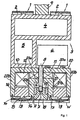
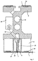
- the holding device 3 is designed substantially as a hollow profile strip and has a plurality of chambers 4, 5.
- the first chamber 4 serves as a compressed air chamber or channel and the second chamber 5 as a vacuum chamber or channel.
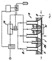
- Compressed air is supplied through the compressed air chamber or the compressed air duct 4, which is supplied from a negative pressure source 6 (see also FIG Fig. 3 ) is converted into negative pressure.
- the negative pressure source 6 is, for example, an ejector, which is acted upon by the compressed air in question on the pressure side and generates on the suction side the desired negative pressure at one or more suction openings 7.
- the vacuum source 6 is connected to the associated intake port 7 via a connection line 8.
- a conventional vacuum pump or a vacuum blower 6 can be used as a vacuum source.
- the invention also allows variants in such a way that both the first chamber 4 and the second chamber 5 are subjected to negative pressure.
- a simultaneous guidance of overpressure through the chambers 4, 5 is conceivable.
- the holding device 3 can be anchored via a central head-side anchor 9 to a frame, to a ceiling or the like fixed point.
- the armature 9 is located centrally between the two circulating conveyor belts 1
- the proposed structure allows a change or an exchange of the relevant commercial conveyor belts 1, without any components of the holding device 3 must be removed.
- individual suction ports 7 can be combined with respective segments of the holding device 3 to transport modules, which can be switched independently. This is necessary in order to be able to drop the transported workpieces W with pinpoint accuracy (cf. EP 0 893 372 A1 ).
- the holding device 3 holds the workpieces W by generating negative pressure at the described suction openings 7 at the respective conveyor belts 1.
- the workpieces W can also be held on the conveyor belt 1 by means of a magnetic field penetrating the respective conveyor belt 1.
- To generate the corresponding magnetic field switchable magnetic devices 10 are provided, which are equipped with at least one permanent magnet 11 and an associated compensation coil 12.
- the negative pressure source 6 which is on the connecting line 8 with the suction port 7 sucking and / or repellent In combination.
- connection line 8 on the one hand to the vacuum chamber 5, on the other hand to the compressed-air chamber 4 in order to be able to represent the corresponding suction or repulsion forces. This is usually done via a pressure switch.
- the holding device 3 is equipped with a raised guide means 13, abut on the longitudinal edges 14 device-side conveyor belt pads on both sides.
- These conveyor belt supports may be the already mentioned teeth of the toothed belt belt or conveyor belt 1.
- the guide device 13 is formed as a cross-sectionally rectangular guide web, as the Fig.1 immediately makes it clear. In principle, of course, deviating cross-sectional formations, for example in the form of a trapezoid, are conceivable.
- the respective guide device 13 is arranged centrally in comparison to the associated conveyor belt 1.
- the corresponding guide means or guide webs 13 are each arranged in the edge region of the conveyor belt 1. It is also recommended that the guide means 13 each magnetically conductive design, so that each forms a north pole and a south pole in the associated guide means 13.
- the Fördemurtauflagen the conveyor belt 1 are equipped with corresponding to the longitudinal edges 14 of the guide means 13 contact surfaces 15. As a result, a perfect axial guidance of the respective conveyor belt 1 is achieved. This applies even more if two (or more) guide means 13 per conveyor belt 1 are realized.
- the respective conveyor belt support in cross section is largely rectangular in shape adapted to the winninggurtbreite edition width, so that the conveyor belt 1 except for the between the longitudinal edges 14 dervoridess workede randomlygurtauflagen 2 formed (rectangular or trapezoidal) recess has a rectangular cross-section.
- the guide device 13 and the rectangular guide bar 13, which may be formed as part of a web 16 dives.
- This web 16 can be carried out magnetically conductive, so that upon realization of two guide means 13 per conveyor belt 1, the described poles (N, S) inevitably arise end.
- Steel strands 17 in the conveyor belt 1 ensure that when the magnetic device 10 is switched on a proper concern of the conveyor belt 1 is ensured on the holding device 3. In particular, the steel strands 10 ensure that no sagging of the conveyor belt 1 occurs.
- Each located between the parallel conveyor belts 1 intake 7 form the end of funnel-like suction nozzles 18.
- the suction nozzles 18 and the suction openings 7 can be adjusted in their distance A relative to the workpieces W. This is indicated by a double arrow in the figures and is realized in detail so that the suction nozzles 18 are connected to the connecting line 8 via a thread.
- the suction nozzles 18 and suction openings 7 can optionally be displaced in the vertical direction, so that the distance A of the suction opening 7 from the respective workpiece W can be varied.
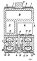
- the embodiments also indicate a variation in that the connecting line 8 opens into a (vacuum) chamber or a vacuum channel U, the /. is sealed off with the aid of a sliding closure piece 19.
- the intake nozzles 18 and the intake ports 7 are arranged in the context of this variant in total in the respective closure member 19 for vacuum channel U.
- the closure member 19 can in turn be adjusted in the direction of the double arrow, so that the desired variation of the distance A of the suction port 7 from the respective workpiece W - as described above - succeeds.
- an outer U-armature 20 are realized with an outer U-base 20a and outer U-legs 20b.
- an inner U-armature 21 which in the same way has an inner U-base 21a and inner U-legs 21b.
- the permanent magnet 11 is arranged, which is a ring magnet or two or more bar magnets of strontium ferrite or neodymium-iron-boron.
- a compensation coil 12 a conventional (oval or round) winding coil is used, which is arranged horizontally and adapted in length to a respective transport module.
- arise at the two U-Schenkein 21 b of the inner U-armature 21 and the two U-legs 20b of the outer U-armature 20 each have the same and mutually opposite magnetic poles.
- the workpiece W has a distance A from an end face or opening plane 22 of the holding device 3.
- the thickness of the conveyor belt 1 specifies the distance A.
- the opening plane 22 is interspersed with suction openings 7 and additionally with ventilation and exhaust openings 23.
- the suction openings 7 and the ventilation and blow-out openings 23 are alternately arranged side by side in the longitudinal extent of the holding device 3, wherein each suction opening 7 is associated with its own ventilation and blow-out opening 23.
- each suction opening 7 is associated with its own ventilation and blow-out opening 23.
- the ventilation and blow-out openings 23 can optionally also be subjected to overpressure or compressed air.
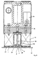
- the circulating around the holding device 3 conveyor belt 1 is formed as a toothed belt.
- With 2 are terminally attached to the holding device 3 attached pulleys or gears.
- a vacuum channel U between the two switchable magnetic devices 10 is diverted.
- two conveyor belts 1 run around the holding device 3.
- the conveyor belts 1 are guided in grooves 24.
- the vacuum duct U is penetrated by ventilation ducts 25. Ventilation openings 26 provided at one end of the ventilation ducts 25 are located in a wall 27 facing the workpieces (not shown here). The ventilation ducts 25 are only opened to the environment at their other end.
- a (not shown here) workpieces facing the outside of the wall 27, which forms the opening plane 22 of the ventilation openings 26 is set back with respect to a (not shown here) by the workpieces W facing outside of the conveyor belts 1 defined conveying plane F with a distance A.
- the gap Z is limited by the conveying plane F, the two conveyor belts 1 and the outside of the wall 27th
- the suction openings 7 are provided in the wall 27 of the vacuum channel U temer.
- the suction openings 7 are formed in connected to the wall 27 intake aperture 28.
- the intake apertures 28 can be screwed into the wall 27, for example.
- the suction orifices 28 are formed conically in the manner of a valve seat on their return channel facing the vacuum channel U.
- valves 34 are turned on, which are preferably electrically switchable.
- the valves 34 may in particular be controllable in groups.
- the ventilation openings 26 and the suction openings 7 are arranged successively each at the same distance along a conveying direction.
- Fig. 7 variant shown is similar to the one in Fig. 6 shown.
- the conveyor belts 1 are here each guided in two grooves 24.
- the end of the compressed air nozzle 29 extends to close to the inside of the suction orifice 28.
- this is expelled through the suction port 7.
- the suction opening 7 is to a certain extent closed dynamically, even if the vacuum channel U continues to be subjected to negative pressure.
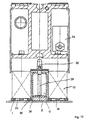
- Fig. 8 shows a plan view of an underside of a third device.
- the two conveyor belts 1 are in turn guided in each case in two grooves 24.
- the opening plane 22 can be seen, in which the intake ports 28 are screwed to the intake ports 7.
- the ventilation openings 26 are here in the form of two marginally arranged on the opening plane 22 slots formed in the slots face each other. They are located approximately in the middle between two intake openings 7.
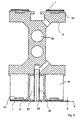
- Fig. 9 shows a cross-sectional view along the section line C - C 'in Fig. 8 ,
- the suction port 7 is funnel-shaped here.
- the compressed air pipe 29 protrudes into the region of the suction opening 7.
- the air is sucked out of the gap Z by an annular gap formed between the compressed air pipe 29 and an opening located in the suction aperture 28.
- the vacuum channel U is received in a ventilation channel 35 here.
- the ventilation duct 35 can be provided with a means (not shown here) for controlling the amount of air passing through the ventilation duct 35. It may be, for example, an air curtain.
- the proposed design is particularly compact
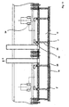
- Fig. 10 shows a cross-sectional view along the section line D - D 'in Fig. 8 , From this view, the connection between the ventilation channel 35 and the slot-shaped ventilation openings 26 clearly emerges.
- Fig. 11 is a longitudinal section along the section line E - E 'in Fig. 8 shown. From this, in particular, the groupwise union of the compressed air connection 29 emerges. Their compressed air supply lines 32 are connected in groups to valves 34.
- valves 34 When the valves 34 are opened, they can be acted upon in groups with compressed air for accurately discharging the workpieces W.
- workpieces W is by means of the magnetic devices 10 generates a magnetic field penetrating the conveyor belts 1
- the workpieces W adhere to the conveyor belts 1.
- the magnetic field is switched off in a predetermined discharge area.
- the vacuum channel U is subjected to a (not shown here) vacuum source with negative pressure.
- a negative pressure flow from the gap Z through the suction openings 7 into the vacuum channel U is formed.
- the negative pressure arising in the gap Z also draws air through the ventilation openings 26 into the gap Z. It forms a dynamic negative pressure, by the action of the workpieces W are held on the conveyor belts 1.
- valves 34 For discharging the workpieces W from the conveyor belt 1, the valves 34, preferably group welwel, opened.
- the leading to the nozzle piston 30 compressed air pipe 29 are acted upon by an overpressure. Possibly. existing nozzle piston 30 are consequently forced against the return action of remindstellfedem 31 against the inside of the intake orifice 28, so that the connection of the intake ports 7 is interrupted to the vacuum channel U.
- compressed air is blown through the nozzle piston 30 in the gap Z.
- the dynamic negative pressure in the gap Z collapses abruptly. The adhering to the conveyor belts 1 workpieces are accurately dropped.
- the vacuum channel U is constantly subjected to a constant negative pressure during operation of the devices described.
- the accurate discharge of the workpieces W can be achieved in this case quickly and easily by applying the Druck Kunststoffstufzen 29 with compressed air in a predetermined range.
- the proposed method is significantly faster than the mere interruption or shutdown of the vacuum flow in the predetermined range.
- the proposed device By means of the proposed device, it is possible to transport both ferromagnetic and non-ferromagnetic workpieces and discard accurately.
- the construction of the device is particularly simple and compact.
Landscapes
- Engineering & Computer Science (AREA)
- Mechanical Engineering (AREA)
- Belt Conveyors (AREA)
- Feeding Of Articles By Means Other Than Belts Or Rollers (AREA)
- Specific Conveyance Elements (AREA)
- Delivering By Means Of Belts And Rollers (AREA)
- Load-Engaging Elements For Cranes (AREA)
Claims (25)
- Dispositif destiné au transport de pièces à usiner, en particulier de pièces à usiner suspendues en forme de panneau telles que des tôles ou des plaques avec
au moins une courroie du convoyeur (1) avec renvoi d'entraînement sur un dispositif de retenue (3) pour le transport de pièces à usiner (W) maintenues par adhérence,
un mécanisme réglable ou pouvant être commandé (6) destiné à la production de dépression étant prévu pour le maintien des pièces à usiner sur la courroie du convoyeur (1),
pour lequel un plan d'ouverture (22) décrit par des orifices d'aspiration (7) par rapport à un plan d'amenée (F) formé par la face extérieure de la courroie du convoyeur (1) est décalé d'un intervalle (A) par rapport au dispositif de retenue (3) de façon qu'un écartement (Z) soit formé entre une pièce à usiner (W) qui adhère à la courroie du convoyeur (1) et le plan d'ouverture (22) et que la pièce à usiner (W) soit retenue sur la courroie du convoyeur (1) par une dépression qui se forme dans l'écartement (Z)
un mécanisme (8, 23, 25 26, 29, 30, 32) étant prévu pour la ventilation de l'écartement (Z) de façon que la pièce à usiner soit retenue sur la courroie du convoyeur (1) par suite de formation d'une dépression dynamique, et le mécanisme de ventilation (8, 23, 25, 26, 29, 30, 32) présentant à intervalles réguliers des orifices de ventilation (23, 26) sur le côté du dispositif de retenue (3) face aux pièces à usiner (W) de façon qu'une dépression dynamique essentiellement constante se règle sur l'ensemble de la longueur de l'écartement (Z). - Dispositif selon la revendication 1, les orifices d'aspiration (7) étant prévus sur une des parois (27) face aux pièces à usiner d'un canal de dépression (U) essentiellement parallèle au sens de transport des pièces à usiner (W).
- Dispositif selon la revendications 2, les orifices d'aspiration (7) étant formés par des buses d'aspiration (28) aménagées dans la paroi (27).
- Dispositif selon la revendication 3, les orifices de ventilation (23, 26) étant aménagés sur la paroi (27) face aux pièces à usiner (W) du canal de dépression (U).
- Dispositif selon l'une des revendications 3 ou 4, chaque orifice de ventilation (23, 26) formant l'extrémité d'un conduit de ventilation (25) pénétrant dans le canal de dépression (U).
- Dispositif selon la revendication 5, les conduits de ventilation (25) étant reliés à un canal de ventilation (35).
- Dispositif selon l'une des revendications précédentes, un mécanisme pour la commande et/ou le réglage de la dépression dynamique étant prévu.
- Dispositif selon l'une des revendications précédentes, un mécanisme étant prévu pour la production optionnelle d'une montée d'air comprimé interrompant la dépression dynamique.
- Dispositif selon la revendication 8, la montée d'air comprimé du canal de dépression (U) étant dirigée vers l'écartement (Z) par les orifices d'aspiration (7).
- Dispositif selon l'une des revendications 8 ou 9, le mécanisme pour la production optionnelle d'une montée d'air comprimé présentant des buses d'air comprimé (29, 30) disposées de manière coaxiale par rapport aux orifices d'aspiration (11).
- Dispositif selon la revendication 10, les buses d'air comprimé (29, 30) pouvant être déplacées de manière axiale par rapport aux orifices d'aspiration (7).
- Dispositif selon l'une des revendications 10 ou 11, les orifices d'aspiration (7) pouvant être fermés au moyen des buses d'air comprimé (29, 30) .
- Dispositif selon l'une des revendications précédentes 10 à 12, les buses d'air comprimé (29, 30) étant aménagées dans le canal de dépression (U) .
- Dispositif selon l'une des revendications précédentes 1 à 13, respectivement un orifice de ventilation (26) et, le cas échéant, une buse d'air comprimé (30) étant attribué à chaque orifice d'aspiration (7).
- Dispositif selon l'une des revendications précédentes 1 à 14, alternativement les orifices d'aspiration (7) et les orifices de ventilation (23, 26) étant disposés successivement dans le sens longitudinal du dispositif de retenue (3).
- Dispositif selon l'une des revendications précédentes 10 à 15, les buses d'air comprimé (29, 30) pouvant être alimentées en air comprimé pour éjecter la pièce à usiner.
- Dispositif selon l'une des revendications précédentes, des aimants (10), de préférence commutables électriquement, sont aménagés dans le dispositif de retenue (3) de façon que des pièces à usiner (W) magnétiques puissent être retenues optionnellement par un champ magnétique adhérant à la courroie du convoyeur (1).
- Dispositif selon l'une des revendications précédentes 2 à 17, le canal de dépression (U) étant disposé entre deux aimants (10).
- Procédé pour le transport de pièces à usiner, en particulier de pièces suspendues en forme de panneau telles que des tôles ou des plaques, au moins une courroie du convoyeur (1) étant avec renvoi sur un dispositif de retenue (3) pour le transport de pièces à usiner (W) maintenues par adhérence,
un mécanisme réglable ou pouvant être commandé (6) destiné à la production d'une dépression étant prévu pour le maintien des pièces à usiner (W) sur la courroie du convoyeur (1),
pour lequel un plan d'ouverture (2) décrit par des orifices d'aspiration (7) par rapport à un plan d'amenée (F) formé par la face extérieure de la courroie du convoyeur (1) est décalé d'un intervalle (A) par rapport au dispositif de retenue (3) de façon qu'un écartement (Z) soit formé entre une pièce à usiner (W) qui adhère à la courroie du convoyeur (1) et le plan d'ouverture (22) et que la pièce à usiner (W) soit retenue sur la courroie du convoyeur (1) par une dépression (U) qui se forme dans l'écartement (Z),
un mécanisme (8, 23, 25, 26, 29, 30, 32) étant prévu pour la ventilation de l'écartement (Z) de façon que la pièce à usiner (W) soit retenue sur la courroie du convoyeur (1) par suite de formation d'une dépression dynamique dans l'écartement (Z), et le mécanisme pour la ventilation le long du dispositif de retenue (3) présentant à intervalles réguliers des orifices de ventilation (23, 26) de façon qu'une dépression dynamique essentiellement constante se règle sur l'ensemble de la longueur de l'écartement (Z). - Procédé selon la revendications 19, la dépression dynamique étant interrompue par une montée d'air comprimé dirigée dans l'écartement (Z) pour éjecter les pièces à usiner (W).
- Procédé selon la revendication 20, la montée d'air comprimé étant dirigée d'un canal de dépression (U) vers l'écartement (Z) par les orifices d'aspiration (7).
- Procédé selon l'une des revendications 19 à 21, la dépression dynamique étant commandée et/ou régulée au moyen du mécanisme (8, 23, 25, 26, 29, 30, 32) pour la ventilation de l'écartement (Z).
- Procédé selon l'une des revendications 20 à 22, des buses d'air comprimé (29, 30) formant la montée d'air comprimé étant déplacées dans le sens axial des orifices d'aspiration (7) à alimentation en air comprimé.
- Procédé selon la revendication 23, les orifices d'aspiration (7) étant fermés à alimentation des buses d'air comprimé (29, 30) en air comprimé, de préférence au moyen des buses d'air comprimé (29, 30).
- Procédé selon l'une des revendications 20 à 24, la montée d'air comprimé étant produite dans un groupe défini d'orifices d'aspiration (7) successifs.
Applications Claiming Priority (3)
| Application Number | Priority Date | Filing Date | Title |
|---|---|---|---|
| DE10104510 | 2001-01-31 | ||
| DE10104510A DE10104510B4 (de) | 2001-01-31 | 2001-01-31 | Vorrichtung zum Transport von Werkstücken |
| PCT/DE2002/000304 WO2002060788A2 (fr) | 2001-01-31 | 2002-01-29 | Dispositif et procede de transport de pieces |
Publications (3)
| Publication Number | Publication Date |
|---|---|
| EP1355838A2 EP1355838A2 (fr) | 2003-10-29 |
| EP1355838B1 EP1355838B1 (fr) | 2004-09-15 |
| EP1355838B2 true EP1355838B2 (fr) | 2011-05-04 |
Family
ID=7672479
Family Applications (1)
| Application Number | Title | Priority Date | Filing Date |
|---|---|---|---|
| EP02706640A Expired - Lifetime EP1355838B2 (fr) | 2001-01-31 | 2002-01-29 | Dispositif et procede de transport de pieces |
Country Status (6)
| Country | Link |
|---|---|
| US (1) | US6823986B2 (fr) |
| EP (1) | EP1355838B2 (fr) |
| AT (1) | ATE276174T1 (fr) |
| DE (2) | DE10104510B4 (fr) |
| ES (1) | ES2229093T5 (fr) |
| WO (1) | WO2002060788A2 (fr) |
Families Citing this family (22)
| Publication number | Priority date | Publication date | Assignee | Title |
|---|---|---|---|---|
| ES2181588B1 (es) * | 2001-05-23 | 2004-06-01 | Asm, S.A. | Maquina transportadora y apiladora para chapas magneticas y no magneticas. |
| DE10342482B3 (de) * | 2003-09-15 | 2004-05-27 | Heidelberger Druckmaschinen Ag | Verfahren und Vorrichtung zur Steuerung der Vakuumverteilung in einem Belichter für Druckvorlagen |
| KR100898793B1 (ko) * | 2005-12-29 | 2009-05-20 | 엘지디스플레이 주식회사 | 액정표시소자용 기판 합착 장치 |
| DE112008003604A5 (de) * | 2007-11-05 | 2010-10-14 | Hennecke Systementwicklung | Einzelplattenförderer, Endloseinzelplattenförderer und Anordnung aus wenigstens zwei Endloseinzelplattenförderern |
| DE202008003610U1 (de) * | 2008-03-16 | 2008-05-21 | Jonas & Redmann Automationstechnik Gmbh | Transportbandsystem mit mindestens einem Transportband zum Transportieren von flachem Transportgut, insbesondere von Substraten wie Siliziumwafer und Solarzellen |
| WO2011009447A2 (fr) * | 2009-07-22 | 2011-01-27 | Zimmermann & Schilp Handhabungstechnik Gmbh | Dispositif pour recevoir et transporter des pièces à usiner plates |
| TWI586599B (zh) * | 2009-07-22 | 2017-06-11 | 契摩曼&許爾波運用技術有限公司 | 用於抓取及輸送平坦工件的裝置 |
| DE202010007281U1 (de) * | 2010-05-27 | 2010-08-19 | Neuhäuser GmbH | Magnetfördereinrichtung |
| EP2431307A3 (fr) * | 2010-09-16 | 2012-04-04 | Montech AG | Transporteur à courroie à vide et soupape de régulation de vide dudit transporteur |
| DE202010013140U1 (de) | 2010-12-16 | 2011-05-05 | Neuhäuser GmbH | Vorrichtung zum Transport von Werkstücken |
| IT1404269B1 (it) * | 2011-02-23 | 2013-11-15 | Bottero Spa | Convogliatore a cinghia per l'avanzamento di una lastra di vetro. |
| WO2015057491A1 (fr) * | 2013-10-14 | 2015-04-23 | Automatic Feed Company | Système convoyeur aérien |
| ITPC20130026A1 (it) * | 2013-12-05 | 2015-06-06 | Fulmec Di Fulcini Fulvio | Dispositivo per il bloccaggio e la movimentazione di un pezzo in una macchina utensile e macchina utensile provvista di detto dispositivo |
| ES2729526T3 (es) | 2016-01-07 | 2019-11-04 | Fagor Arrasate S Coop | Dispositivo de transporte de piezas y método para transportar piezas |
| DE102016214095A1 (de) * | 2016-07-29 | 2018-02-01 | Asys Automatisierungssysteme Gmbh | Vorrichtung zum Greifen und Transportieren von Substraten |
| DE102016214094A1 (de) * | 2016-07-29 | 2018-02-01 | Asys Automatisierungssysteme Gmbh | Vorrichtung zum Greifen und Transportieren von Substraten |
| DE102016121396A1 (de) | 2016-11-09 | 2018-05-09 | Phoenix Contact Gmbh & Co. Kg | Fördersystem zum Fördern mindestens eines Werkstücks |
| ES2847172T3 (es) | 2018-05-17 | 2021-08-02 | Fagor Arrasate S Coop | Dispositivo de transporte de piezas |
| CN109671659A (zh) * | 2018-12-24 | 2019-04-23 | 苏州沃特维自动化系统有限公司 | 电池片连续悬浮上料系统 |
| DE102020111238A1 (de) | 2020-04-24 | 2021-10-28 | Schuler Pressen Gmbh | Verfahren und Vorrichtung zum Vereinzeln von Platinen |
| EP4349742B1 (fr) | 2022-10-04 | 2025-11-26 | Neuhäuser GmbH | Dispositif de nettoyage pour courroie de transport |
| DE202025107819U1 (de) | 2025-12-18 | 2026-05-07 | Neuhäuser GmbH | Vorrichtung zum Transport von Werkstücken |
Citations (3)
| Publication number | Priority date | Publication date | Assignee | Title |
|---|---|---|---|---|
| EP0893372A1 (fr) † | 1997-07-24 | 1999-01-27 | Neuhäuser GMBH + CO. | Dispositif pour le transport de pièces d'oeuvre, notamment de pièces suspendues tabulaires |
| EP1061020A1 (fr) † | 1999-06-15 | 2000-12-20 | Systraplan Gesellschaft für Planung und Bau von materialflusstechnischen Anlagen mbH u. Co. KG | Dispositif au sol pour alimenter ou évacuer des lignes de procédé pour articles plats |
| WO2002022479A1 (fr) † | 2000-09-18 | 2002-03-21 | Strålfors Ab | Convoyeur pour feuilles ou bande |
Family Cites Families (18)
| Publication number | Priority date | Publication date | Assignee | Title |
|---|---|---|---|---|
| US3182998A (en) * | 1962-12-21 | 1965-05-11 | American Can Co | Conveyor |
| US3628654A (en) * | 1969-10-01 | 1971-12-21 | Edward F Haracz | Vacuum belt conveyors |
| US3708058A (en) * | 1971-01-08 | 1973-01-02 | Gaf Corp | Vacuum belt conveyor |
| US3802699A (en) * | 1971-03-22 | 1974-04-09 | Littell F Machine Co | Conveying apparatus with overlapping means for stacking purposes |
| JPS552362B2 (fr) * | 1972-09-11 | 1980-01-19 | ||
| DE3686781D1 (de) * | 1985-05-04 | 1992-10-29 | Seibu Giken Kk | Vorrichtung zum halten und/oder foerdern einer platte mittels eines fluids ohne koerperliche beruehrung. |
| DE3539876A1 (de) * | 1985-11-11 | 1987-05-14 | Karl Lenhardt | Vorrichtung fuer das schlupffreie foerdern von stueckgut in beliebiger position, insbesondere in geneigter oder im wesentlichen vertikaler stellung |
| JP2505273Y2 (ja) * | 1990-01-26 | 1996-07-24 | 池上通信機株式会社 | 被検体搬送装置 |
| DE4342753A1 (de) * | 1993-12-15 | 1995-06-22 | Schuler Gmbh L | Mit Saugluft arbeitende Vorrichtung zum hängenden Transport von Blechen |
| US5857605A (en) * | 1995-06-26 | 1999-01-12 | Marquip, Inc. | Vacuum assisted web drive for corrugator double backer |
| US6102191A (en) * | 1996-04-15 | 2000-08-15 | Tridelta Magnetsysteme Gmbh | Device for transporting flat, especially plate-like objects |
| US5878868A (en) * | 1996-05-06 | 1999-03-09 | Ikegami Tsushinki Co., Ltd. | Object inspection apparatus |
| DE19636160A1 (de) * | 1996-09-06 | 1998-03-12 | Nsm Magnettechnik Gmbh | Bandfördereinrichtung für die hängende Beförderung von Transportgütern mit Unterdruck |
| DE19727361C5 (de) * | 1997-06-27 | 2004-02-05 | Wemhöner Fördertechnik GmbH & Co KG | Fördervorrichtung |
| DE19833313C2 (de) * | 1998-06-25 | 2003-10-30 | Schuler Automation Gmbh & Co | Bandförderer zum Transport von plattenförmigen Werkstücken |
| AU771257B2 (en) * | 1999-03-22 | 2004-03-18 | Komax Holding Ag | Vacuum assisted walking beam apparatus |
| DE19942498B4 (de) * | 1999-09-06 | 2008-02-07 | Nsm Magnettechnik Gmbh & Co. Kg | Bandfördereinrichtung für den insbesondere hängenden Transport von Transportgütern mittels Unterdruck |
| DE29915611U1 (de) * | 1999-09-07 | 2000-02-24 | NSM Magnettechnik GmbH & Co. KG, 59399 Olfen | Transportvorrichtung |
-
2001
- 2001-01-31 DE DE10104510A patent/DE10104510B4/de not_active Expired - Fee Related
-
2002
- 2002-01-29 EP EP02706640A patent/EP1355838B2/fr not_active Expired - Lifetime
- 2002-01-29 AT AT02706640T patent/ATE276174T1/de active
- 2002-01-29 WO PCT/DE2002/000304 patent/WO2002060788A2/fr not_active Ceased
- 2002-01-29 DE DE50201012T patent/DE50201012D1/de not_active Expired - Lifetime
- 2002-01-29 ES ES02706640T patent/ES2229093T5/es not_active Expired - Lifetime
- 2002-01-29 US US10/470,821 patent/US6823986B2/en not_active Expired - Fee Related
Patent Citations (3)
| Publication number | Priority date | Publication date | Assignee | Title |
|---|---|---|---|---|
| EP0893372A1 (fr) † | 1997-07-24 | 1999-01-27 | Neuhäuser GMBH + CO. | Dispositif pour le transport de pièces d'oeuvre, notamment de pièces suspendues tabulaires |
| EP1061020A1 (fr) † | 1999-06-15 | 2000-12-20 | Systraplan Gesellschaft für Planung und Bau von materialflusstechnischen Anlagen mbH u. Co. KG | Dispositif au sol pour alimenter ou évacuer des lignes de procédé pour articles plats |
| WO2002022479A1 (fr) † | 2000-09-18 | 2002-03-21 | Strålfors Ab | Convoyeur pour feuilles ou bande |
Also Published As
| Publication number | Publication date |
|---|---|
| ATE276174T1 (de) | 2004-10-15 |
| EP1355838B1 (fr) | 2004-09-15 |
| EP1355838A2 (fr) | 2003-10-29 |
| DE10104510A1 (de) | 2003-07-31 |
| WO2002060788A3 (fr) | 2003-01-03 |
| US6823986B2 (en) | 2004-11-30 |
| ES2229093T5 (es) | 2011-09-29 |
| DE10104510B4 (de) | 2005-06-23 |
| DE50201012D1 (de) | 2004-10-21 |
| ES2229093T3 (es) | 2005-04-16 |
| US20040060801A1 (en) | 2004-04-01 |
| WO2002060788A2 (fr) | 2002-08-08 |
Similar Documents
| Publication | Publication Date | Title |
|---|---|---|
| EP1355838B2 (fr) | Dispositif et procede de transport de pieces | |
| EP0893372B1 (fr) | Dispositif pour le transport de pièces d'oeuvre, notamment de pièces suspendues tabulaires | |
| EP1081067B2 (fr) | Convoyeur à courroie en particulier pour le transport suspendu par dépression de marchandises | |
| DE19636086A1 (de) | Magnetbandförderer für den hängenden Transport von Blechen o. dgl. | |
| WO1992002316A1 (fr) | Dispositif de refroidissement de profiles extrudes | |
| EP0850697A2 (fr) | Dispositif pour l'application de matériaux fluides sur un substrat, en particulier pour l'application intermittente de colles fluides | |
| DE10213705B4 (de) | Vorrichtung zum Fördern eines Bogenstroms von einem Bogenstapel zu einer bogenverarbeitenden Maschine | |
| EP2611697A2 (fr) | Dispositif d'étiquetage | |
| EP1914004B1 (fr) | Procédé de commande d'un pulvérisateur de poudre | |
| EP0515350B1 (fr) | Ejecteur | |
| DE102009019785B4 (de) | Vorrichtung zum Transportieren von tafelförmigen Gütern | |
| EP3140056A1 (fr) | Déflecteur de bande et ensemble de cylindre | |
| DE102005057426A1 (de) | Unterdruck-Bandfördervorrichtung zum Führen einer laufenden Bahn | |
| EP0733574A2 (fr) | Dispositif pour traiter des cahiers de feuilles ou similaires | |
| EP3292049B1 (fr) | Dispositif et procédé d'étiquetage de produits individuels | |
| DE2645464C2 (de) | Einrichtung zum unmittelbaren Fördern von leichten Gegenständen in einer Rinne | |
| EP1699721B2 (fr) | Dispositif de guidage flottant d'un materiau en bande | |
| DE19731901C2 (de) | Vorrichtung zum insbesondere hängenden Transport von Werkstücken, insbesondere tafelförmigen Werkstücken wie Blechen oder Platten | |
| DE20219672U1 (de) | Vorrichtung zum Transport von Werkstücken | |
| DE19823582C2 (de) | Vorrichtung zum Transport von Werkstücken | |
| DE102009032907B3 (de) | Vorrichtung zum Entfernen von Rückständen von der Oberfläche eines bewegten Bandes sowie Bandbearbeitungsanlage | |
| DE1942439A1 (de) | Einrichtung zum Anliefern von Schriftstuecken | |
| DE102007058405A1 (de) | Umlenkvorrichtung zum Umlenken von flexiblem Flachmaterial | |
| DE102006033007B3 (de) | Vorrichtung zur Luftkühlung von Presssträngen | |
| DE102005001568A1 (de) | Vorrichtung zum Transport von Werkstücken |
Legal Events
| Date | Code | Title | Description |
|---|---|---|---|
| PUAI | Public reference made under article 153(3) epc to a published international application that has entered the european phase |
Free format text: ORIGINAL CODE: 0009012 |
|
| 17P | Request for examination filed |
Effective date: 20030606 |
|
| AK | Designated contracting states |
Kind code of ref document: A2 Designated state(s): AT BE CH CY DE DK ES FI FR GB GR IE IT LI LU MC NL PT SE TR |
|
| GRAP | Despatch of communication of intention to grant a patent |
Free format text: ORIGINAL CODE: EPIDOSNIGR1 |
|
| GRAS | Grant fee paid |
Free format text: ORIGINAL CODE: EPIDOSNIGR3 |
|
| GRAA | (expected) grant |
Free format text: ORIGINAL CODE: 0009210 |
|
| AK | Designated contracting states |
Kind code of ref document: B1 Designated state(s): AT BE CH CY DE DK ES FI FR GB GR IE IT LI LU MC NL PT SE TR |
|
| PG25 | Lapsed in a contracting state [announced via postgrant information from national office to epo] |
Ref country code: TR Free format text: LAPSE BECAUSE OF FAILURE TO SUBMIT A TRANSLATION OF THE DESCRIPTION OR TO PAY THE FEE WITHIN THE PRESCRIBED TIME-LIMIT Effective date: 20040915 Ref country code: GB Free format text: LAPSE BECAUSE OF FAILURE TO SUBMIT A TRANSLATION OF THE DESCRIPTION OR TO PAY THE FEE WITHIN THE PRESCRIBED TIME-LIMIT Effective date: 20040915 Ref country code: IE Free format text: LAPSE BECAUSE OF FAILURE TO SUBMIT A TRANSLATION OF THE DESCRIPTION OR TO PAY THE FEE WITHIN THE PRESCRIBED TIME-LIMIT Effective date: 20040915 Ref country code: FR Free format text: LAPSE BECAUSE OF FAILURE TO SUBMIT A TRANSLATION OF THE DESCRIPTION OR TO PAY THE FEE WITHIN THE PRESCRIBED TIME-LIMIT Effective date: 20040915 Ref country code: NL Free format text: LAPSE BECAUSE OF FAILURE TO SUBMIT A TRANSLATION OF THE DESCRIPTION OR TO PAY THE FEE WITHIN THE PRESCRIBED TIME-LIMIT Effective date: 20040915 Ref country code: FI Free format text: LAPSE BECAUSE OF FAILURE TO SUBMIT A TRANSLATION OF THE DESCRIPTION OR TO PAY THE FEE WITHIN THE PRESCRIBED TIME-LIMIT Effective date: 20040915 |
|
| REG | Reference to a national code |
Ref country code: CH Ref legal event code: EP Ref country code: GB Ref legal event code: FG4D Free format text: NOT ENGLISH |
|
| REG | Reference to a national code |
Ref country code: IE Ref legal event code: FG4D Free format text: GERMAN |
|
| REF | Corresponds to: |
Ref document number: 50201012 Country of ref document: DE Date of ref document: 20041021 Kind code of ref document: P |
|
| PG25 | Lapsed in a contracting state [announced via postgrant information from national office to epo] |
Ref country code: DK Free format text: LAPSE BECAUSE OF FAILURE TO SUBMIT A TRANSLATION OF THE DESCRIPTION OR TO PAY THE FEE WITHIN THE PRESCRIBED TIME-LIMIT Effective date: 20041215 Ref country code: GR Free format text: LAPSE BECAUSE OF FAILURE TO SUBMIT A TRANSLATION OF THE DESCRIPTION OR TO PAY THE FEE WITHIN THE PRESCRIBED TIME-LIMIT Effective date: 20041215 Ref country code: SE Free format text: LAPSE BECAUSE OF FAILURE TO SUBMIT A TRANSLATION OF THE DESCRIPTION OR TO PAY THE FEE WITHIN THE PRESCRIBED TIME-LIMIT Effective date: 20041215 |
|
| PG25 | Lapsed in a contracting state [announced via postgrant information from national office to epo] |
Ref country code: CY Free format text: LAPSE BECAUSE OF FAILURE TO SUBMIT A TRANSLATION OF THE DESCRIPTION OR TO PAY THE FEE WITHIN THE PRESCRIBED TIME-LIMIT Effective date: 20050129 Ref country code: LU Free format text: LAPSE BECAUSE OF NON-PAYMENT OF DUE FEES Effective date: 20050129 |
|
| PG25 | Lapsed in a contracting state [announced via postgrant information from national office to epo] |
Ref country code: BE Free format text: LAPSE BECAUSE OF NON-PAYMENT OF DUE FEES Effective date: 20050131 Ref country code: MC Free format text: LAPSE BECAUSE OF NON-PAYMENT OF DUE FEES Effective date: 20050131 |
|
| NLV1 | Nl: lapsed or annulled due to failure to fulfill the requirements of art. 29p and 29m of the patents act | ||
| GBV | Gb: ep patent (uk) treated as always having been void in accordance with gb section 77(7)/1977 [no translation filed] |
Effective date: 20040915 |
|
| REG | Reference to a national code |
Ref country code: ES Ref legal event code: FG2A Ref document number: 2229093 Country of ref document: ES Kind code of ref document: T3 |
|
| REG | Reference to a national code |
Ref country code: IE Ref legal event code: FD4D |
|
| PLAQ | Examination of admissibility of opposition: information related to despatch of communication + time limit deleted |
Free format text: ORIGINAL CODE: EPIDOSDOPE2 |
|
| PLAR | Examination of admissibility of opposition: information related to receipt of reply deleted |
Free format text: ORIGINAL CODE: EPIDOSDOPE4 |
|
| PLBQ | Unpublished change to opponent data |
Free format text: ORIGINAL CODE: EPIDOS OPPO |
|
| PLBI | Opposition filed |
Free format text: ORIGINAL CODE: 0009260 |
|
| PLAX | Notice of opposition and request to file observation + time limit sent |
Free format text: ORIGINAL CODE: EPIDOSNOBS2 |
|
| BERE | Be: lapsed |
Owner name: SCHULER AUTOMATION G.M.B.H. & CO. KG Effective date: 20050131 |
|
| 26 | Opposition filed |
Opponent name: NSM MAGNETTECHNIK GMBH Effective date: 20050603 |
|
| EN | Fr: translation not filed | ||
| PLBB | Reply of patent proprietor to notice(s) of opposition received |
Free format text: ORIGINAL CODE: EPIDOSNOBS3 |
|
| PG25 | Lapsed in a contracting state [announced via postgrant information from national office to epo] |
Ref country code: CH Free format text: LAPSE BECAUSE OF NON-PAYMENT OF DUE FEES Effective date: 20060131 Ref country code: LI Free format text: LAPSE BECAUSE OF NON-PAYMENT OF DUE FEES Effective date: 20060131 |
|
| REG | Reference to a national code |
Ref country code: CH Ref legal event code: PL |
|
| PLAY | Examination report in opposition despatched + time limit |
Free format text: ORIGINAL CODE: EPIDOSNORE2 |
|
| PLBC | Reply to examination report in opposition received |
Free format text: ORIGINAL CODE: EPIDOSNORE3 |
|
| BERE | Be: lapsed |
Owner name: *SCHULER AUTOMATION G.M.B.H. & CO. K.G. Effective date: 20050131 |
|
| PG25 | Lapsed in a contracting state [announced via postgrant information from national office to epo] |
Ref country code: PT Free format text: LAPSE BECAUSE OF NON-PAYMENT OF DUE FEES Effective date: 20050215 |
|
| APAH | Appeal reference modified |
Free format text: ORIGINAL CODE: EPIDOSCREFNO |
|
| APBP | Date of receipt of notice of appeal recorded |
Free format text: ORIGINAL CODE: EPIDOSNNOA2O |
|
| APBQ | Date of receipt of statement of grounds of appeal recorded |
Free format text: ORIGINAL CODE: EPIDOSNNOA3O |
|
| APBU | Appeal procedure closed |
Free format text: ORIGINAL CODE: EPIDOSNNOA9O |
|
| PUAH | Patent maintained in amended form |
Free format text: ORIGINAL CODE: 0009272 |
|
| STAA | Information on the status of an ep patent application or granted ep patent |
Free format text: STATUS: PATENT MAINTAINED AS AMENDED |
|
| 27A | Patent maintained in amended form |
Effective date: 20110504 |
|
| AK | Designated contracting states |
Kind code of ref document: B2 Designated state(s): AT BE CH CY DE DK ES FI FR GB GR IE IT LI LU MC NL PT SE TR |
|
| REG | Reference to a national code |
Ref country code: DE Ref legal event code: R102 Ref document number: 50201012 Country of ref document: DE Effective date: 20110504 |
|
| REG | Reference to a national code |
Ref country code: ES Ref legal event code: DC2A Ref document number: 2229093 Country of ref document: ES Kind code of ref document: T5 Effective date: 20110929 |
|
| PGFP | Annual fee paid to national office [announced via postgrant information from national office to epo] |
Ref country code: DE Payment date: 20120216 Year of fee payment: 11 |
|
| PGFP | Annual fee paid to national office [announced via postgrant information from national office to epo] |
Ref country code: IT Payment date: 20120126 Year of fee payment: 11 |
|
| PGFP | Annual fee paid to national office [announced via postgrant information from national office to epo] |
Ref country code: AT Payment date: 20120123 Year of fee payment: 11 |
|
| PGFP | Annual fee paid to national office [announced via postgrant information from national office to epo] |
Ref country code: ES Payment date: 20120124 Year of fee payment: 11 |
|
| REG | Reference to a national code |
Ref country code: AT Ref legal event code: MM01 Ref document number: 276174 Country of ref document: AT Kind code of ref document: T Effective date: 20130131 |
|
| PG25 | Lapsed in a contracting state [announced via postgrant information from national office to epo] |
Ref country code: AT Free format text: LAPSE BECAUSE OF NON-PAYMENT OF DUE FEES Effective date: 20130131 Ref country code: DE Free format text: LAPSE BECAUSE OF NON-PAYMENT OF DUE FEES Effective date: 20130801 |
|
| REG | Reference to a national code |
Ref country code: DE Ref legal event code: R119 Ref document number: 50201012 Country of ref document: DE Effective date: 20130801 |
|
| PG25 | Lapsed in a contracting state [announced via postgrant information from national office to epo] |
Ref country code: IT Free format text: LAPSE BECAUSE OF NON-PAYMENT OF DUE FEES Effective date: 20130129 |
|
| REG | Reference to a national code |
Ref country code: ES Ref legal event code: FD2A Effective date: 20140321 |
|
| PG25 | Lapsed in a contracting state [announced via postgrant information from national office to epo] |
Ref country code: ES Free format text: LAPSE BECAUSE OF NON-PAYMENT OF DUE FEES Effective date: 20130130 |