EP1355838B1 - Dispositif et procede de transport de pieces - Google Patents
Dispositif et procede de transport de pieces Download PDFInfo
- Publication number
- EP1355838B1 EP1355838B1 EP02706640A EP02706640A EP1355838B1 EP 1355838 B1 EP1355838 B1 EP 1355838B1 EP 02706640 A EP02706640 A EP 02706640A EP 02706640 A EP02706640 A EP 02706640A EP 1355838 B1 EP1355838 B1 EP 1355838B1
- Authority
- EP
- European Patent Office
- Prior art keywords
- compressed air
- negative pressure
- gap
- conveyor belt
- work pieces
- Prior art date
- Legal status (The legal status is an assumption and is not a legal conclusion. Google has not performed a legal analysis and makes no representation as to the accuracy of the status listed.)
- Expired - Lifetime
Links
- 238000000034 method Methods 0.000 title claims description 17
- 229910052751 metal Inorganic materials 0.000 claims abstract description 4
- 239000002184 metal Substances 0.000 claims abstract description 4
- 230000000717 retained effect Effects 0.000 claims abstract 7
- 230000005291 magnetic effect Effects 0.000 claims description 28
- 230000001105 regulatory effect Effects 0.000 claims description 4
- 238000013022 venting Methods 0.000 abstract 1
- 238000009423 ventilation Methods 0.000 description 49
- 229910000831 Steel Inorganic materials 0.000 description 5
- 230000005294 ferromagnetic effect Effects 0.000 description 5
- 239000010959 steel Substances 0.000 description 5
- 230000015572 biosynthetic process Effects 0.000 description 3
- 238000010276 construction Methods 0.000 description 3
- 230000000149 penetrating effect Effects 0.000 description 3
- 229910052782 aluminium Inorganic materials 0.000 description 2
- XAGFODPZIPBFFR-UHFFFAOYSA-N aluminium Chemical compound [Al] XAGFODPZIPBFFR-UHFFFAOYSA-N 0.000 description 2
- 230000000694 effects Effects 0.000 description 2
- 239000003302 ferromagnetic material Substances 0.000 description 2
- QJVKUMXDEUEQLH-UHFFFAOYSA-N [B].[Fe].[Nd] Chemical compound [B].[Fe].[Nd] QJVKUMXDEUEQLH-UHFFFAOYSA-N 0.000 description 1
- 230000015556 catabolic process Effects 0.000 description 1
- 230000001276 controlling effect Effects 0.000 description 1
- 230000001419 dependent effect Effects 0.000 description 1
- 238000005516 engineering process Methods 0.000 description 1
- 239000011521 glass Substances 0.000 description 1
- 239000000463 material Substances 0.000 description 1
- 229910001172 neodymium magnet Inorganic materials 0.000 description 1
- 230000001846 repelling effect Effects 0.000 description 1
- 238000007665 sagging Methods 0.000 description 1
- 238000007789 sealing Methods 0.000 description 1
- 230000003068 static effect Effects 0.000 description 1
- 229910052712 strontium Inorganic materials 0.000 description 1
- CIOAGBVUUVVLOB-UHFFFAOYSA-N strontium atom Chemical compound [Sr] CIOAGBVUUVVLOB-UHFFFAOYSA-N 0.000 description 1
- 238000011144 upstream manufacturing Methods 0.000 description 1
- 238000004804 winding Methods 0.000 description 1
- 239000002023 wood Substances 0.000 description 1
- 229910000859 α-Fe Inorganic materials 0.000 description 1
Images


Classifications
-
- B—PERFORMING OPERATIONS; TRANSPORTING
- B65—CONVEYING; PACKING; STORING; HANDLING THIN OR FILAMENTARY MATERIAL
- B65G—TRANSPORT OR STORAGE DEVICES, e.g. CONVEYORS FOR LOADING OR TIPPING, SHOP CONVEYOR SYSTEMS OR PNEUMATIC TUBE CONVEYORS
- B65G21/00—Supporting or protective framework or housings for endless load-carriers or traction elements of belt or chain conveyors
- B65G21/20—Means incorporated in, or attached to, framework or housings for guiding load-carriers, traction elements or loads supported on moving surfaces
- B65G21/2027—Suction retaining means
- B65G21/2036—Suction retaining means for retaining the load on the load-carrying surface
-
- B—PERFORMING OPERATIONS; TRANSPORTING
- B65—CONVEYING; PACKING; STORING; HANDLING THIN OR FILAMENTARY MATERIAL
- B65G—TRANSPORT OR STORAGE DEVICES, e.g. CONVEYORS FOR LOADING OR TIPPING, SHOP CONVEYOR SYSTEMS OR PNEUMATIC TUBE CONVEYORS
- B65G47/00—Article or material-handling devices associated with conveyors; Methods employing such devices
- B65G47/74—Feeding, transfer, or discharging devices of particular kinds or types
- B65G47/90—Devices for picking-up and depositing articles or materials
- B65G47/91—Devices for picking-up and depositing articles or materials incorporating pneumatic, e.g. suction, grippers
- B65G47/911—Devices for picking-up and depositing articles or materials incorporating pneumatic, e.g. suction, grippers with air blasts producing partial vacuum
Definitions
- the invention relates to an apparatus and a method for Transport of workpieces according to the preambles of the claims 1 and 20.
- suction nozzle is a special vacuum generating device assigned. To control the vacuum the vacuum generators can now and then individually or in groups be turned on. In particular for dropping am Workpieces adhering to the conveyor belt become those in the discharge area located vacuum generating devices switched off.
- the suction nozzles are at a short distance here arranged to the transport side of the workpiece. The distance between the transport side of the workpieces and the suction nozzles is chosen so small that only a small amount of False air remaining through the two edges of the workpiece Opening slots is sucked. It kind of imagines stationary vacuum.
- the known device is relatively complex. It a large number of vacuum generating devices must be provided. This requires a relatively large amount of space.
- the known device is not particularly compact. Because of the formation of a stationary negative pressure large workpieces with a higher force per unit area tightened to the conveyor belt as small workpieces. Dependent on The drive motor must match the respective workpiece size be driven with a different power so the conveying speed can be kept constant. The Applying a static vacuum also causes that this slows down when switching off large workpieces degrades than with small workpieces. Depending on the size and The weight of the adhering workpiece is only found when it is ejected after a different period of time after Switching off the vacuum generating devices instead. through the known device is a targeted dropping of Workpieces not possible.
- the object of the invention is to overcome the disadvantages of the prior art of technology to eliminate.
- it is intended to be a device for hanging transport of non-magnetic workpieces are specified, which are simple and inexpensive to produce is.
- Another object of the invention is a device as well as to specify a procedure with which a precise dropping of workpieces of different sizes and different Weight is equally possible.
- a device for ventilation of the gap is provided is so that the workpiece by a developing dynamic Vacuum is kept on the conveyor belt.
- a dynamic vacuum is understood to mean a vacuum, which follows the Venturi principle as a result of a Current forms.
- the flow is directed from the ventilation device to the suction openings.
- Condition for the Setting a dynamic vacuum is that per unit of time a sufficiently high volume flow through the ventilation device fed to the gap and through the suction openings is suctioned off again. Then a for forms in the gap the generation of the vacuum sufficiently high flow rate out.
- the size of the negative pressure results from the Bernoulli equation. Typical flow rates are between 60 and 80 m / sec.
- the formation of the invention provided dynamic negative pressure has the Advantage that workpieces, regardless of their size, always with same specific force per unit area on the conveyor belt being held. A precise dropping is independent of the size of the workpiece possible.
- the workpieces can without Regulating the power of a drive unit always with the same Speed can be transported.
- the suction openings on a wall facing the workpieces parallel to the transport direction of the workpieces Vacuum channel provided.
- the provision of a common vacuum channel is eliminated the need to cover each of the intake ports with a to provide special vacuum generating device.
- the Device can be used with a single with the vacuum channel connected vacuum generating device can be operated. It can be built compactly.
- the provision of a common Vacuum channel also creates constructive freedom, the to take up funds for the targeted dropping of the Workpieces can be used.
- the suction openings formed by suction nozzles accommodated in the wall This makes it possible to use the device depending on the requirement profile to be equipped with a suitable intake cross-section.
- the device for ventilation on the the side of the holding device facing the workpieces at regular intervals Arrangement ventilation openings so that A substantially uniform one over the entire length of the gap sets dynamic vacuum.
- the ventilation device can also be used on the workpiece side be provided, e.g. then when the workpiece Breakthroughs of a suitable size or a suitable uneven Has surface formation. Through the device for ventilation it is ensured that workpieces regardless of their Size held on the conveyor belt at all times with the same force become.
- the ventilation openings can be on the workpieces facing wall of the vacuum channel his.
- Each of the ventilation openings expediently forms the end of a ventilation line penetrating the vacuum duct, which are connected to a ventilation duct can.
- the ventilation duct can be used for ventilation with the environment related, but it can also be related to a minor Overpressure can be applied.
- a device for control and / or is expedient Regulation of the dynamic vacuum provided. It can a device for controlling and / or regulating a the vacuum source acting on the vacuum channel act. By means of the device e.g. the Speed of a vacuum source used as a vacuum source to be changed. But it can also be a means of control the amount of air passing through the ventilation duct be provided. This makes the device particularly universal. It can e.g. by setting an air screen can be easily adapted to the respective requirement profile.
- the vacuum channel is constantly with a predetermined Vacuum applied, which is dimensioned so that itself when placing a workpiece on the conveyor belt Gap quickly builds up the required flow rate.
- the device for the optional generation of a dynamic Negative pressure interrupting compressed air pulse can be provided.
- the device for generating a blast of compressed air can be along a predetermined area of the holding device is provided his.
- the specified range can be one Act the drop zone of the workpieces.
- The is expediently Blast of compressed air from the vacuum duct through the suction openings facing the gap. This enables a compact design.
- the dynamic vacuum can throw off the workpieces not only be interrupted, but it can also Air is blown into the specified area of the gap and so that the workpieces can be quickly ejected. If when generating the air blast in the specified range air continues to be sucked in through the suction openings must be supplied with the compressed air pulse per unit of time Air volume may be greater than that through the intake openings extracted air volume.
- the device is arranged coaxially to the suction openings Compressed air nozzles.
- the compressed air nozzles can counter axially the suction openings can be moved back and forth.
- the suction openings can be closed by means of the compressed air nozzles are. When closed, it can pass through the suction openings no air from the gap into the vacuum duct be sucked in more.
- suction openings it is also possible to use the suction openings to close.
- Compressed air nozzles with pistons adjustable by compressed air are used which optionally close the suction openings.
- each suction opening is in each case assigned a ventilation opening and possibly a compressed air nozzle.
- a ventilation opening and possibly a compressed air nozzle are assigned to each suction opening.
- the suction openings and the ventilation openings can alternately in the longitudinal extent of the holding device be arranged one behind the other. The aforementioned features contribute to a simplified construction. The device can be produced inexpensively.
- the compressed air nozzles can be used to eject the workpieces Compressed air.
- the compressed air nozzles for the precise ejection of a workpiece may be controlled in groups or to be supplied with compressed air.
- one known from the prior art Control device may be provided.
- the holding device preferably electrically switchable magnets are added so that magnetic workpieces are optional are adhered to the conveyor belt by a magnetic field.
- the vacuum channel is arranged between the magnets.
- According to the invention is also in a method for hanging Transport of workpieces, especially tabular workpieces such as sheets or plates, provided that a device is provided for ventilation of the gap, so that Workpiece through a dynamic formed in the gap Vacuum is kept on the conveyor belt.
- a dynamic vacuum can be applied Construction on those known from the prior art elaborate sealing measures when using a stationary vacuum can be dispensed with.
- the device for ventilation along the holding device in regular Arrangement ventilation openings on, so that over the entire Gap length a substantially uniform dynamic Sets negative pressure. This ensures that the workpieces are always at all points along the gap be tightened to the conveyor belt with the same force.
- the dynamic one is expediently used to eject the workpieces Negative pressure due to a blast of compressed air directed into the gap interrupted.
- the proposed method works a sudden breakdown of the dynamic vacuum. Workpieces adhering to the conveyor belt can thus thrown precisely.
- the blast of compressed air can be from one Vacuum channel directed through the suction openings to the gap his. The provision of such a vacuum channel continues to ensure that a suitable for performing the method Device can be built compact and simple.
- the dynamic vacuum can also be provided by a device controlled and / or regulated to vent the gap.
- a predetermined amount of air can be supplied to the gap.
- the ventilation device can be attached to the work piece facing wall of the vacuum duct ventilation openings exhibit. Each vent can be the end of a vacuum duct form a thorough ventilation duct.
- the Ventilation openings are expediently provided with a ventilation duct connected.
- the dynamic negative pressure can be by means of a device for control and / or regulation set become. It can be a facility with which controls and / or regulates the ventilation of the gap becomes.
- the compressed air nozzles are advantageous when acted upon moved axially with compressed air in the direction of the intake openings.
- the suction openings can be activated when the Compressed air nozzles with compressed air, preferably by means of the compressed air nozzles, be closed.
- the aforementioned process steps contribute to the dynamic vacuum particularly is dismantled quickly and efficiently.
- the blast of compressed air is preferably predetermined Group of successive suction openings created.
- at least one can be upstream further suction opening arranged in the group of suction openings be closed to eject the workpiece.
- the suction opening can e.g. by means of a pressurized air Pistons are closed. This measure contributes to the fact that in the edge region of the drop zone possibly setting undesired dynamic negative pressure is avoided.
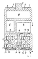
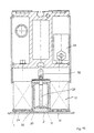
- Figures 1 to 3 is a first device for transport of workpieces W, which are hanging, tabular sheets or plates. These sheets or plates can basically be made of any material his. So the device is not only suitable for Transport of ferromagnetic or magnetizable workpieces W or sheet metal, but also for onward transport of aluminum plates. In addition, of course also glass plates, plastic plates or even wood-based panels be transported. Of course there is also a overlying transport possible and conceivable, such as it is in WO 97/38927, there FIG. 3, described in detail 30 becomes.
- the device in question is equipped with two conveyor belts 1 running in parallel, which are driven all around by means of the toothed wheels or pulleys 2 shown in FIG. 4.
- the conveyor belts 1 are, in the context of the variant shown, toothed belt belts 1 which engage with corresponding teeth in corresponding recesses (not shown here) on the belt pulleys 2 for driving them.
- the two conveyor belts or toothed belt belts 1 are guided past a holding device 3.
- the holding device 3 is essentially a hollow profile strip designed and has several chambers 4, 5. there the first chamber 4 serves as a compressed air chamber or duct and the second chamber 5 as a vacuum chamber or channel. By the compressed air chamber or the compressed air channel 4 becomes compressed air fed from a vacuum source connected to it 6 (see also Fig. 3) is converted into negative pressure.
- the vacuum source 6 is within the scope of the exemplary embodiment e.g. around an ejector, which is on the pressure side with the relevant compressed air and on the suction side the desired vacuum at one or more suction openings 7 generated. For this purpose, the vacuum source 6 to the associated suction opening 7 via a connecting line 8 connected.
- a connecting line 8 connected.
- the invention also allows variants of this type to that both the first chamber 4 and the second chamber 5 are subjected to negative pressure. Also a simultaneous one Guiding overpressure through the chambers 4, 5 is conceivable.
- the holding device 3 can be located on a central head Anchor 9 on a frame, on a ceiling or the like Fixed point to be anchored.
- the anchor 9 is in the middle arranged between the two rotating conveyor belts 1.
- the proposed structure enables a change or one Exchange of the relevant commercial conveyor belts 1, without that any components of the holder 3 removed Need to become.
- individual Intake openings 7 with respective segments of the holding device 3 can be combined into transport modules that are have each switch independently. That is required precisely around the transported workpieces W. to be able to throw off (see also EP 0 893 372 A1).
- the holding device 3 holds the workpieces W by generating of negative pressure at the described suction openings 7 to the respective conveyor belts 1 fixed.
- the workpieces W by means of a respective Conveyor belt 1 penetrating magnetic field on the conveyor belt 1 are recorded.
- the Switchable magnetic devices 10 are provided in the magnetic field, those with at least one permanent magnet 11 and one associated compensation coil 12 are equipped.
- the negative pressure source 6, which is connected to the suction opening 7 via the connecting line 8 in a sucking and / or repelling manner, provides for the required negative pressure at the respective suction opening 7. It is basically also conceivable to connect the connecting line 8 to the vacuum chamber 5 on the one hand, and to the compressed air chamber 4 on the other hand, in order to be able to represent the corresponding suction or repulsion forces. This is usually done using a pressure switch.
- the guide device 13 is rectangular in cross section Guide bar formed, like FIG. 1 immediately makes it clear.
- Cross-sectional training for example in the form of a Trapezes, conceivable.
- the respective guide device 13 in the middle in comparison to the associated Conveyor belt 1 arranged.
- two guide devices are also conceivable 13 per conveyor belt 1 can be realized.
- the guiding devices 13 can be magnetically conductive, so that there is a north pole and a south pole forms in the associated guide device 13.
- the conveyor belt supports of the conveyor belt 1 are included in the Longitudinal edges 14 of the guide device 13 corresponding Contact surfaces 15 equipped. This will make a flawless axial guidance of the respective conveyor belt 1 reached. The applies even more when two (or more) management institutions 13 per conveyor belt 1 can be realized.
- the respective conveyor belt support is in cross section for the most part rectangular with the width of the conveyor belt Support width formed so that the conveyor belt 1 except for that between the longitudinal edges 14 of the device side Conveyor belt supports 2 formed (rectangular or trapezoidal) Recess has a rectangular cross section.
- the guide device 13 or the rectangular guide web 13, which as a component of a web 16 can be formed.
- This web 16 can be made magnetically conductive, so that when implemented of two guide devices 13 per conveyor belt 1 described poles (N, S) inevitably arise at the ends.
- Steel strands 17 in the conveyor belt 1 ensure that when switched on Magnetic device 10 a perfect concern of the conveyor belt 1 guaranteed on the holding device 3 is. In particular, the steel strands 10 ensure that none Sagging of the conveyor belt 1 occurs.
- the respectively between the parallel conveyor belts 1 located suction openings 7 form the end of funnel-like suction nozzles 18.
- the suction nozzles 18 and the suction openings 7 can be compared in their distance A. adjust the workpieces W. That is through a double arrow indicated in the figures and is realized in detail so that the suction nozzles 18 with the connecting line 8th are connected by a thread.
- the intake nozzles 18 or suction openings 7 optionally in the vertical direction be moved so that the distance A of the suction opening 7 can be varied from the respective workpiece W.
- the exemplary embodiments also indicate a variation in such a way that the connecting line 8 into a (vacuum) Chamber or a vacuum channel U opens, the / the e.g. partitioned off with the aid of a sliding closure piece 19 becomes.
- the suction nozzles 18 and the suction openings 7 as part of this variant in total in the Closure piece 19 for vacuum channel U arranged.
- the closure piece 19 can in turn in the direction of Adjust the double arrow so that the desired variation of the Distance A of the suction opening 7 from the respective workpiece W - as described above - succeed.
- the magnetic device 10 engages 10 within the scope of the exemplary embodiment according to FIG. 1 on a permanent magnet 11 and an associated compensation coil 12 back.
- an outer U-anchor 20 is included an outer U-base 20a and outer U-legs 20b realized.
- an inner one U-anchor 21 which in the same way is an inner U-base 21a and inner U-legs 21b.
- the permanent magnet 11 which is a ring magnet or two or more bar magnets made of strontium ferrite or neodymium iron boron, is arranged between the two respective U bases 20a and 21a.
- a conventional (oval or round) winding coil is used as the compensation coil 12, which is arranged horizontally and its length is adapted to a respective transport module.
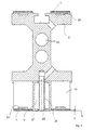
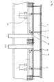
- the device according to FIGS. 1 and 2 shown in partial longitudinal section. Consequently recognizes one of the two commercially available conveyor belts 1.
- the raised guide device 13 or comparable Measures the workpiece W has a distance A of one End face or opening plane 22 of the holding device 3.
- the thickness of the conveyor belt 1 the distance A.
- the opening level 22 is with suction openings 7 as well interspersed with ventilation and blow-out openings 23.
- the Intake openings 7 and the ventilation and exhaust openings 23 are alternately in the longitudinal extent of the holding device 3rd arranged side by side, each suction opening 7 a own ventilation and blow-out opening 23 is assigned.
- each suction opening 7 a own ventilation and blow-out opening 23 is assigned.
- the ventilation and blow-out openings 23 can also optionally with excess pressure or compressed air.
- Ventilation lines 25 are provided at one end of the ventilation lines 25 Ventilation openings 26 are in one Wall (not shown here) facing workpieces 27.
- the Ventilation lines 25 are only at their other end open to the environment.
- the wall 27, which is the opening plane 22 of the ventilation openings 26 is opposite to one by the Workpieces W (not shown here) facing outside the conveyor belts 1 defined conveyor plane F at a distance A set back.
- the gap Z is limited by the conveyor level F, the two conveyor belts 1 and the outside of the Wall 27.
- the suction openings 7 are also provided.
- the suction openings 7 are connected to the wall 27 Intake orifices 28 formed.
- the intake panels 28 can e.g. be screwed into the wall 27.
- the intake panels 28 are conical on their back side facing the vacuum channel U. trained in the manner of a valve seat.
- At 29 are compressed air sockets protruding into the vacuum duct U. referred to, on which axially displaceable nozzle piston 30 is added are. Return springs 31 force the nozzle piston 30 in an open position, i.e. a position in which the suction openings 7 are connected to the vacuum duct U.
- the compressed air nozzle 29 are over at their other ends Compressed air feeds 32 connected to a compressed air duct 33.
- Valves 34 are switched into the compressed air supply lines 32, which are preferably electrically switchable.
- the Valves 34 can in particular be controllable in groups.
- the ventilation openings are 26 and the suction openings 7 in succession each at the same distance along a conveying direction arranged.
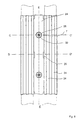
- FIG. 7 The variant shown in FIG. 7 is similar to that shown in FIG. 6.
- the conveyor belts 1 are each in two grooves 24 guided.
- the end of the compressed air nozzle 29 extends to close the inside of the intake panel 28.
- the suction opening 7 is in this Case closed to a certain extent dynamically, even if the vacuum channel U is still pressurized.
- the two conveyor belts 1 are here again each guided in two grooves 24. Between the two Transport belts 1, the opening level 22 can be seen, in which the intake panels 28 are screwed in with the intake openings 7 are. There are also the openings of the compressed air nozzle 29 recognizable.
- the ventilation openings 26 are in here Shape of two edges arranged at the opening plane 22 Slots formed. The slots face each other. They are located approximately in the middle between two suction openings 7th
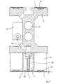
- FIG. 9 shows a cross-sectional view along the section line C - C 'in Fig. 8.
- the suction opening 7 is funnel-shaped here educated.
- the compressed air connection 29 projects into the area of the Intake opening 7.
- the air is released from the gap Z through a between the compressed air nozzle 29 and one in the intake panel 28 located breakthrough suction formed annular gap.
- the vacuum duct U is received in a ventilation duct 35.
- the ventilation duct 35 can be equipped with a (not shown here) Means to control the through the ventilation duct 35 passing amount of air. It can doing e.g. to be an air blind.
- the proposed one The design is particularly compact.
- FIG. 10 shows a cross-sectional view along the section line D - D 'in Fig. 8. From this view the connection is clear between the ventilation duct 35 and the slot-shaped ventilation openings 26 out.
- FIG. 11 is a longitudinal section along the section line E - E ' shown in Fig. 8. From this comes in particular the groups Interconnection of the compressed air nozzle 29. Their compressed air supply 32 are connected in groups to valves 34.
- tabular workpieces W For transporting, made of a ferromagnetic material, in particular, tabular workpieces W is the conveyor belts by means of the magnetic devices 10 1 penetrating magnetic field generated. The workpieces W stick on the conveyor belts 1. To throw off the workpieces W the magnetic field is switched off in a predetermined discharge area.
- the vacuum channel U For transporting from a non-ferromagnetic material manufactured, in particular tabular, workpieces W, e.g. Aluminum sheets, the vacuum channel U with a vacuum source (not shown here) with vacuum applied. A vacuum flow from the Gap Z through the suction openings 7 into the vacuum channel U. Due to the negative pressure in the gap Z, there is also Air through the ventilation openings 26 in the gap Z sucked. A dynamic negative pressure develops through the effect of which the workpieces W are held on the conveyor belts 1 become.
- a vacuum source not shown here
- Valves 34 preferably in groups, opened.
- the nozzle piston 30 compressed air is blown into the Z gap. The dynamic negative pressure in the gap Z suddenly collapses. The on the conveyor belts 1 adhering workpieces are discarded precisely.
- the operation of the devices described is advantageous the vacuum channel U constantly with a constant Vacuum applied.
- the precise dropping of the workpieces In this case, W can be applied quickly and easily the compressed air nozzle 29 with compressed air in a predetermined Range can be reached.
- the proposed procedure is much faster than the mere interruption or that Switching off the vacuum flow in the specified range.
- the proposed device By means of the proposed device it is possible to both Ferromagnetic and non-ferromagnetic workpieces to transport and to throw off precisely.
- the construction the device is particularly simple and compact educated.
Landscapes
- Engineering & Computer Science (AREA)
- Mechanical Engineering (AREA)
- Belt Conveyors (AREA)
- Feeding Of Articles By Means Other Than Belts Or Rollers (AREA)
- Specific Conveyance Elements (AREA)
- Load-Engaging Elements For Cranes (AREA)
- Delivering By Means Of Belts And Rollers (AREA)
Claims (27)
- Dispositif destiné au transport de pièces à usiner, en particulier de pièces à usiner suspendues en forme de panneau telles que des tôles ou des plaques avec
au moins une courroie du convoyeur (1) avec renvoi d'entraínement sur un dispositif de retenue (3) pour le transport de pièces à usiner (W) maintenues par adhérence,
un mécanisme réglable ou pouvant être commandé (6) destiné à la production de dépression étant prévu pour le maintien des pièces à usiner sur la courroie du convoyeur (1),
pour lequel un plan d'ouverture (22) décrit par des orifices d'aspiration (7) par rapport à un plan d'amenée (F) formé par la face extérieure de la courroie du convoyeur (1) est décalé d'un intervalle (A) par rapport au dispositif de retenue (3) de façon qu'un écartement (Z) soit formé entre une pièce à usiner (W) qui adhère à la courroie du convoyeur (1) et le plan d'ouverture (22) et que la pièce à usiner (W) soit retenue sur la courroie du convoyeur (1) par une dépression qui se forme dans l'écartement (Z),
caractérisé par le fait qu'un mécanisme (8, 23, 25 26, 29, 30, 32) est prévu pour la ventilation de l'écartement (Z) de façon que la pièce à usiner soit retenue sur la courroie du convoyeur (1) par suite de formation d'une dépression dynamique. - Dispositif selon la revendication 1, les orifices d'aspiration (7) étant prévus sur une des parois (27) face aux pièces à usiner d'un canal de dépression (U) essentiellement parallèle au sens de transport des pièces à usiner (W).
- Dispositif selon la revendication 2, les orifices d'aspiration (7) étant formés par des buses d'aspiration (28) aménagées dans la paroi (27).
- Dispositif selon l'une des revendications précédentes, le mécanisme de ventilation (8, 23, 25, 26, 29, 30, 32) présentant à intervalles réguliers des orifices de ventilation (23, 26) sur le côté du dispositif de retenue (3) face aux pièces à usiner (W) de façon qu'une dépression dynamique essentiellement constante se règle sur l'ensemble de la longueur de l'écartement (Z).
- Dispositif selon la revendication 4, les orifices de ventilation (23, 26) étant aménagés sur la paroi (27) face aux pièces à usiner (W) du canal de dépression (U).
- Dispositif selon l'une des revendications 4 ou 5, chaque orifice de ventilation (23, 26) formant l'extrémité d'un conduit de ventilation (25) pénétrant dans le canal de dépression (U).
- Dispositif selon la revendication 6, les conduits de ventilation (25) étant reliés à un canal de ventilation (35).
- Dispositif selon l'une des revendications précédentes, un mécanisme pour la commande et/ou le réglage de la dépression dynamique étant prévu.
- Dispositif selon l'une des revendications précédentes, un mécanisme étant prévu pour la production optionnelle d'une montée d'air comprimé interrompant la dépression dynamique.
- Dispositif selon la revendication 9, la montée d'air comprimé du canal de dépression (U) étant dirigée vers l'écartement (Z) par les orifices d'aspiration (7).
- Dispositif selon l'une des revendications 9 ou 10, le mécanisme pour la production optionnelle d'une montée d'air comprimé présentant des buses d'air comprimé (29, 30) disposées de manière coaxiale par rapport aux orifices d'aspiration (11).
- Dispositif selon la revendication 11, les buses d'air comprimé (29, 30) pouvant être déplacées de manière axiale par rapport aux orifices d'aspiration (7).
- Dispositif selon l'une des revendications 11 ou 12, les orifices d'aspiration (7) pouvant être fermés au moyen des buses d'air comprimé (29, 30).
- Dispositif selon l'une des revendications précédentes 11 à 13, les buses d'air comprimé (29, 30) étant aménagées dans le canal de dépression (U).
- Dispositif selon l'une des revendications précédentes 4 à 14, respectivement un orifice de ventilation (26) et, le cas échéant, une buse d'air comprimé (30) étant attribué à chaque orifice d'aspiration (7).
- Dispositif selon l'une des revendications précédentes 4 à 15, alternativement les orifices d'aspiration (7) et les orifices de ventilation (23, 26) étant disposés successivement dans le sens longitudinal du dispositif de retenue (3).
- Dispositif selon l'une des revendications précédentes 11 à 16, les buses d'air comprimé (29, 30) pouvant être alimentées en air comprimé pour éjecter la pièce à usiner.
- Dispositif selon l'une des revendications précédentes, des aimants (10), de préférence commutables électriquement, sont aménagés dans le dispositif de retenue (3) de façon que des pièces à usiner (W) magnétiques puissent être retenues optionnellement par un champ magnétique adhérant à la courroie du convoyeur (1).
- Dispositif selon l'une des revendications précédentes 2 à 18, le canal de dépression (U) étant disposé entre deux aimants (10).
- Procédé pour le transport de pièces à usiner, en particulier de pièces suspendues en forme de panneau telles que des tôles ou des plaques, au moins une courroie du convoyeur (1) étant avec renvoi sur un dispositif de retenue (3) pour le transport de pièces à usiner (W) maintenues par adhérence,
un mécanisme réglable ou pouvant être commandé (6) destiné à la production d'une dépression étant prévu pour le maintien des pièces à usiner (W) sur la courroie du convoyeur (1),
pour lequel un plan d'ouverture (2) décrit par des orifices d'aspiration (7) par rapport à un plan d'amenée (F) formé par la face extérieure de la courroie du convoyeur (1) est décalé d'un intervalle (A) par rapport au dispositif de retenue (3) de façon qu'un écartement (Z) soit formé entre une pièce à usiner (W) qui adhère à la courroie du convoyeur (1) et le plan d'ouverture (22) et que la pièce à usiner (W) soit retenue sur la courroie du convoyeur (1) par une dépression (U) qui se forme dans l'écartement (Z),
caractérisé par le fait qu'un mécanisme (8, 23, 25, 26, 29, 30, 32) est prévu pour la ventilation de l'écartement (Z) de façon que la pièce à usiner (W) soit retenue sur la courroie du convoyeur (1) par suite de formation d'une dépression dynamique dans l'écartement (Z). - Procédé selon la revendication 20, le mécanisme pour la ventilation le long du dispositif de retenue (3) présentant à intervalles réguliers des orifices de ventilation (23, 26) de façon qu'une dépression dynamique essentiellement constante se règle sur l'ensemble de la longueur de l'écartement (Z).
- Procédé selon la revendication 20 ou 21, la dépression dynamique étant interrompue par une montée d'air comprimé dirigée dans l'écartement (Z) pour éjecter les pièces à usiner (W).
- Procédé selon la revendication 22, la montée d'air comprimé étant dirigée d'un canal de dépression (U) vers l'écartement (Z) par les orifices d'aspiration (7).
- Procédé selon l'une des revendications 20 à 23, la dépression dynamique étant commandée et/ou réglée au moyen du mécanisme (8, 23, 25, 26, 29, 30, 32) pour la ventilation de l'écartement (Z).
- Procédé selon l'une des revendications 22 à 24, des buses d'air comprimé (29, 30) formant la montée d'air comprimé étant déplacées dans le sens axial des orifices d'aspiration (7) à alimentation en air comprimé.
- Procédé selon la revendication 25, les orifices d'aspiration (7) étant fermés à alimentation des buses d'air comprimé (29, 30) en air comprimé, de préférence au moyen des buses d'air comprimé (29, 30).
- Procédé selon l'une des revendications 22 à 26, la montée d'air comprimé étant produite dans un groupe défini d'orifices d'aspiration (7) successifs.
Applications Claiming Priority (3)
| Application Number | Priority Date | Filing Date | Title |
|---|---|---|---|
| DE10104510 | 2001-01-31 | ||
| DE10104510A DE10104510B4 (de) | 2001-01-31 | 2001-01-31 | Vorrichtung zum Transport von Werkstücken |
| PCT/DE2002/000304 WO2002060788A2 (fr) | 2001-01-31 | 2002-01-29 | Dispositif et procede de transport de pieces |
Publications (3)
| Publication Number | Publication Date |
|---|---|
| EP1355838A2 EP1355838A2 (fr) | 2003-10-29 |
| EP1355838B1 true EP1355838B1 (fr) | 2004-09-15 |
| EP1355838B2 EP1355838B2 (fr) | 2011-05-04 |
Family
ID=7672479
Family Applications (1)
| Application Number | Title | Priority Date | Filing Date |
|---|---|---|---|
| EP02706640A Expired - Lifetime EP1355838B2 (fr) | 2001-01-31 | 2002-01-29 | Dispositif et procede de transport de pieces |
Country Status (6)
| Country | Link |
|---|---|
| US (1) | US6823986B2 (fr) |
| EP (1) | EP1355838B2 (fr) |
| AT (1) | ATE276174T1 (fr) |
| DE (2) | DE10104510B4 (fr) |
| ES (1) | ES2229093T5 (fr) |
| WO (1) | WO2002060788A2 (fr) |
Cited By (2)
| Publication number | Priority date | Publication date | Assignee | Title |
|---|---|---|---|---|
| US10000342B2 (en) | 2016-01-07 | 2018-06-19 | Fagor Arrasate, S. Coop. | Conveying device for conveying goods and method for conveying goods |
| DE102020111238A1 (de) | 2020-04-24 | 2021-10-28 | Schuler Pressen Gmbh | Verfahren und Vorrichtung zum Vereinzeln von Platinen |
Families Citing this family (20)
| Publication number | Priority date | Publication date | Assignee | Title |
|---|---|---|---|---|
| ES2181588B1 (es) * | 2001-05-23 | 2004-06-01 | Asm, S.A. | Maquina transportadora y apiladora para chapas magneticas y no magneticas. |
| DE10342482B3 (de) * | 2003-09-15 | 2004-05-27 | Heidelberger Druckmaschinen Ag | Verfahren und Vorrichtung zur Steuerung der Vakuumverteilung in einem Belichter für Druckvorlagen |
| KR100898793B1 (ko) * | 2005-12-29 | 2009-05-20 | 엘지디스플레이 주식회사 | 액정표시소자용 기판 합착 장치 |
| DE112008003604A5 (de) * | 2007-11-05 | 2010-10-14 | Hennecke Systementwicklung | Einzelplattenförderer, Endloseinzelplattenförderer und Anordnung aus wenigstens zwei Endloseinzelplattenförderern |
| DE202008003610U1 (de) * | 2008-03-16 | 2008-05-21 | Jonas & Redmann Automationstechnik Gmbh | Transportbandsystem mit mindestens einem Transportband zum Transportieren von flachem Transportgut, insbesondere von Substraten wie Siliziumwafer und Solarzellen |
| TWI586599B (zh) * | 2009-07-22 | 2017-06-11 | 契摩曼&許爾波運用技術有限公司 | 用於抓取及輸送平坦工件的裝置 |
| WO2011009447A2 (fr) * | 2009-07-22 | 2011-01-27 | Zimmermann & Schilp Handhabungstechnik Gmbh | Dispositif pour recevoir et transporter des pièces à usiner plates |
| DE202010007281U1 (de) * | 2010-05-27 | 2010-08-19 | Neuhäuser GmbH | Magnetfördereinrichtung |
| EP2431307A3 (fr) * | 2010-09-16 | 2012-04-04 | Montech AG | Transporteur à courroie à vide et soupape de régulation de vide dudit transporteur |
| DE202010013140U1 (de) | 2010-12-16 | 2011-05-05 | Neuhäuser GmbH | Vorrichtung zum Transport von Werkstücken |
| IT1404269B1 (it) * | 2011-02-23 | 2013-11-15 | Bottero Spa | Convogliatore a cinghia per l'avanzamento di una lastra di vetro. |
| MX372125B (es) * | 2013-10-14 | 2020-03-03 | Automatic Feed Company | Sistema de transportador aéreo. |
| ITPC20130026A1 (it) * | 2013-12-05 | 2015-06-06 | Fulmec Di Fulcini Fulvio | Dispositivo per il bloccaggio e la movimentazione di un pezzo in una macchina utensile e macchina utensile provvista di detto dispositivo |
| DE102016214094A1 (de) * | 2016-07-29 | 2018-02-01 | Asys Automatisierungssysteme Gmbh | Vorrichtung zum Greifen und Transportieren von Substraten |
| DE102016214095A1 (de) * | 2016-07-29 | 2018-02-01 | Asys Automatisierungssysteme Gmbh | Vorrichtung zum Greifen und Transportieren von Substraten |
| DE102016121396A1 (de) | 2016-11-09 | 2018-05-09 | Phoenix Contact Gmbh & Co. Kg | Fördersystem zum Fördern mindestens eines Werkstücks |
| EP3569530B1 (fr) | 2018-05-17 | 2020-11-04 | Fagor Arrasate, S.Coop. | Dispositif de transport pour transporter des marchandises |
| CN109671659A (zh) * | 2018-12-24 | 2019-04-23 | 苏州沃特维自动化系统有限公司 | 电池片连续悬浮上料系统 |
| EP4349742B1 (fr) | 2022-10-04 | 2025-11-26 | Neuhäuser GmbH | Dispositif de nettoyage pour courroie de transport |
| DE202025107819U1 (de) | 2025-12-18 | 2026-05-07 | Neuhaeuser Gmbh | Vorrichtung zum Transport von Werkstücken |
Family Cites Families (21)
| Publication number | Priority date | Publication date | Assignee | Title |
|---|---|---|---|---|
| US3182998A (en) * | 1962-12-21 | 1965-05-11 | American Can Co | Conveyor |
| US3628654A (en) * | 1969-10-01 | 1971-12-21 | Edward F Haracz | Vacuum belt conveyors |
| US3708058A (en) * | 1971-01-08 | 1973-01-02 | Gaf Corp | Vacuum belt conveyor |
| US3802699A (en) * | 1971-03-22 | 1974-04-09 | Littell F Machine Co | Conveying apparatus with overlapping means for stacking purposes |
| JPS552362B2 (fr) * | 1972-09-11 | 1980-01-19 | ||
| DE3686781D1 (de) * | 1985-05-04 | 1992-10-29 | Seibu Giken Kk | Vorrichtung zum halten und/oder foerdern einer platte mittels eines fluids ohne koerperliche beruehrung. |
| DE3539876A1 (de) * | 1985-11-11 | 1987-05-14 | Karl Lenhardt | Vorrichtung fuer das schlupffreie foerdern von stueckgut in beliebiger position, insbesondere in geneigter oder im wesentlichen vertikaler stellung |
| JP2505273Y2 (ja) * | 1990-01-26 | 1996-07-24 | 池上通信機株式会社 | 被検体搬送装置 |
| DE4342753A1 (de) * | 1993-12-15 | 1995-06-22 | Schuler Gmbh L | Mit Saugluft arbeitende Vorrichtung zum hängenden Transport von Blechen |
| US5857605A (en) * | 1995-06-26 | 1999-01-12 | Marquip, Inc. | Vacuum assisted web drive for corrugator double backer |
| US6102191A (en) * | 1996-04-15 | 2000-08-15 | Tridelta Magnetsysteme Gmbh | Device for transporting flat, especially plate-like objects |
| US5878868A (en) * | 1996-05-06 | 1999-03-09 | Ikegami Tsushinki Co., Ltd. | Object inspection apparatus |
| DE19636160A1 (de) * | 1996-09-06 | 1998-03-12 | Nsm Magnettechnik Gmbh | Bandfördereinrichtung für die hängende Beförderung von Transportgütern mit Unterdruck |
| DE19727361C5 (de) * | 1997-06-27 | 2004-02-05 | Wemhöner Fördertechnik GmbH & Co KG | Fördervorrichtung |
| ES2143881T5 (es) * | 1997-07-24 | 2004-06-16 | Neuhauser Gmbh + Co. | Dispositivo para el transporte de piezas, en particular de piezas suspendidas en forma tubular. |
| DE19833313C2 (de) * | 1998-06-25 | 2003-10-30 | Schuler Automation Gmbh & Co | Bandförderer zum Transport von plattenförmigen Werkstücken |
| ATE308476T1 (de) * | 1999-03-22 | 2005-11-15 | Ascor Inc | Vakuumunterstützte hubbalkenvorrichtung |
| EP1061020A1 (fr) † | 1999-06-15 | 2000-12-20 | Systraplan Gesellschaft für Planung und Bau von materialflusstechnischen Anlagen mbH u. Co. KG | Dispositif au sol pour alimenter ou évacuer des lignes de procédé pour articles plats |
| DE19942498B4 (de) * | 1999-09-06 | 2008-02-07 | Nsm Magnettechnik Gmbh & Co. Kg | Bandfördereinrichtung für den insbesondere hängenden Transport von Transportgütern mittels Unterdruck |
| DE29915611U1 (de) * | 1999-09-07 | 2000-02-24 | NSM Magnettechnik GmbH & Co. KG, 59399 Olfen | Transportvorrichtung |
| SE523483C2 (sv) † | 2000-09-18 | 2004-04-20 | Straalfors Ab | Anordning för transport av ark i en anordning i vilken ingår en höghastighetsprinter |
-
2001
- 2001-01-31 DE DE10104510A patent/DE10104510B4/de not_active Expired - Fee Related
-
2002
- 2002-01-29 EP EP02706640A patent/EP1355838B2/fr not_active Expired - Lifetime
- 2002-01-29 US US10/470,821 patent/US6823986B2/en not_active Expired - Fee Related
- 2002-01-29 ES ES02706640T patent/ES2229093T5/es not_active Expired - Lifetime
- 2002-01-29 WO PCT/DE2002/000304 patent/WO2002060788A2/fr not_active Ceased
- 2002-01-29 AT AT02706640T patent/ATE276174T1/de active
- 2002-01-29 DE DE50201012T patent/DE50201012D1/de not_active Expired - Lifetime
Cited By (3)
| Publication number | Priority date | Publication date | Assignee | Title |
|---|---|---|---|---|
| US10000342B2 (en) | 2016-01-07 | 2018-06-19 | Fagor Arrasate, S. Coop. | Conveying device for conveying goods and method for conveying goods |
| DE102020111238A1 (de) | 2020-04-24 | 2021-10-28 | Schuler Pressen Gmbh | Verfahren und Vorrichtung zum Vereinzeln von Platinen |
| WO2021213990A1 (fr) | 2020-04-24 | 2021-10-28 | Schuler Pressen Gmbh | Procédé et dispositif permettant d'individualiser des plaques |
Also Published As
| Publication number | Publication date |
|---|---|
| WO2002060788A3 (fr) | 2003-01-03 |
| EP1355838A2 (fr) | 2003-10-29 |
| US6823986B2 (en) | 2004-11-30 |
| DE10104510A1 (de) | 2003-07-31 |
| ATE276174T1 (de) | 2004-10-15 |
| EP1355838B2 (fr) | 2011-05-04 |
| ES2229093T3 (es) | 2005-04-16 |
| WO2002060788A2 (fr) | 2002-08-08 |
| DE50201012D1 (de) | 2004-10-21 |
| US20040060801A1 (en) | 2004-04-01 |
| ES2229093T5 (es) | 2011-09-29 |
| DE10104510B4 (de) | 2005-06-23 |
Similar Documents
| Publication | Publication Date | Title |
|---|---|---|
| EP1355838B1 (fr) | Dispositif et procede de transport de pieces | |
| EP0893372B1 (fr) | Dispositif pour le transport de pièces d'oeuvre, notamment de pièces suspendues tabulaires | |
| EP0541630B1 (fr) | Dispositif de refroidissement de profiles extrudes | |
| EP0850697B1 (fr) | Dispositif pour l'application de matériaux fluides sur un substrat, en particulier pour l'application intermittente de colles fluides | |
| EP1081067B2 (fr) | Convoyeur à courroie en particulier pour le transport suspendu par dépression de marchandises | |
| EP3446991B1 (fr) | Dispositif de rétractation et procédé d'aspiration d'air à partir d'un espace intérieur d'un dispositif de rétractation | |
| DE19636086A1 (de) | Magnetbandförderer für den hängenden Transport von Blechen o. dgl. | |
| DE10213705B4 (de) | Vorrichtung zum Fördern eines Bogenstroms von einem Bogenstapel zu einer bogenverarbeitenden Maschine | |
| EP2253384B2 (fr) | Dispositif de revêtement pour pièces allongées | |
| EP0904242B1 (fr) | Dispositif pour transporter des articles plats, se presentant notamment sous forme de plaques | |
| DE102005057426A1 (de) | Unterdruck-Bandfördervorrichtung zum Führen einer laufenden Bahn | |
| EP0733574A2 (fr) | Dispositif pour traiter des cahiers de feuilles ou similaires | |
| EP3292049B1 (fr) | Dispositif et procédé d'étiquetage de produits individuels | |
| EP0002055B1 (fr) | Dispositif et procédé pour la trempe thermique simultanée de plusieurs feuilles de verre suspendues côte à côte en position de repos | |
| DE2645464C2 (de) | Einrichtung zum unmittelbaren Fördern von leichten Gegenständen in einer Rinne | |
| DE20219672U1 (de) | Vorrichtung zum Transport von Werkstücken | |
| EP1699721B2 (fr) | Dispositif de guidage flottant d'un materiau en bande | |
| DE19731901C2 (de) | Vorrichtung zum insbesondere hängenden Transport von Werkstücken, insbesondere tafelförmigen Werkstücken wie Blechen oder Platten | |
| DE102005001568A1 (de) | Vorrichtung zum Transport von Werkstücken | |
| DE3521691A1 (de) | Verfahren und vorrichtung zum seitlichen ausrichten von bogen | |
| DE102009032907B3 (de) | Vorrichtung zum Entfernen von Rückständen von der Oberfläche eines bewegten Bandes sowie Bandbearbeitungsanlage | |
| DE1942439A1 (de) | Einrichtung zum Anliefern von Schriftstuecken | |
| DE102006033007B3 (de) | Vorrichtung zur Luftkühlung von Presssträngen | |
| EP1792861B1 (fr) | Dispositif de transport à bande sous vide pour guider une bande en mouvement | |
| DE19833311C2 (de) | Bandförderer zum Transport von plattenförmigen Werkstücken |
Legal Events
| Date | Code | Title | Description |
|---|---|---|---|
| PUAI | Public reference made under article 153(3) epc to a published international application that has entered the european phase |
Free format text: ORIGINAL CODE: 0009012 |
|
| 17P | Request for examination filed |
Effective date: 20030606 |
|
| AK | Designated contracting states |
Kind code of ref document: A2 Designated state(s): AT BE CH CY DE DK ES FI FR GB GR IE IT LI LU MC NL PT SE TR |
|
| GRAP | Despatch of communication of intention to grant a patent |
Free format text: ORIGINAL CODE: EPIDOSNIGR1 |
|
| GRAS | Grant fee paid |
Free format text: ORIGINAL CODE: EPIDOSNIGR3 |
|
| GRAA | (expected) grant |
Free format text: ORIGINAL CODE: 0009210 |
|
| AK | Designated contracting states |
Kind code of ref document: B1 Designated state(s): AT BE CH CY DE DK ES FI FR GB GR IE IT LI LU MC NL PT SE TR |
|
| PG25 | Lapsed in a contracting state [announced via postgrant information from national office to epo] |
Ref country code: TR Free format text: LAPSE BECAUSE OF FAILURE TO SUBMIT A TRANSLATION OF THE DESCRIPTION OR TO PAY THE FEE WITHIN THE PRESCRIBED TIME-LIMIT Effective date: 20040915 Ref country code: GB Free format text: LAPSE BECAUSE OF FAILURE TO SUBMIT A TRANSLATION OF THE DESCRIPTION OR TO PAY THE FEE WITHIN THE PRESCRIBED TIME-LIMIT Effective date: 20040915 Ref country code: IE Free format text: LAPSE BECAUSE OF FAILURE TO SUBMIT A TRANSLATION OF THE DESCRIPTION OR TO PAY THE FEE WITHIN THE PRESCRIBED TIME-LIMIT Effective date: 20040915 Ref country code: FR Free format text: LAPSE BECAUSE OF FAILURE TO SUBMIT A TRANSLATION OF THE DESCRIPTION OR TO PAY THE FEE WITHIN THE PRESCRIBED TIME-LIMIT Effective date: 20040915 Ref country code: NL Free format text: LAPSE BECAUSE OF FAILURE TO SUBMIT A TRANSLATION OF THE DESCRIPTION OR TO PAY THE FEE WITHIN THE PRESCRIBED TIME-LIMIT Effective date: 20040915 Ref country code: FI Free format text: LAPSE BECAUSE OF FAILURE TO SUBMIT A TRANSLATION OF THE DESCRIPTION OR TO PAY THE FEE WITHIN THE PRESCRIBED TIME-LIMIT Effective date: 20040915 |
|
| REG | Reference to a national code |
Ref country code: CH Ref legal event code: EP Ref country code: GB Ref legal event code: FG4D Free format text: NOT ENGLISH |
|
| REG | Reference to a national code |
Ref country code: IE Ref legal event code: FG4D Free format text: GERMAN |
|
| REF | Corresponds to: |
Ref document number: 50201012 Country of ref document: DE Date of ref document: 20041021 Kind code of ref document: P |
|
| PG25 | Lapsed in a contracting state [announced via postgrant information from national office to epo] |
Ref country code: DK Free format text: LAPSE BECAUSE OF FAILURE TO SUBMIT A TRANSLATION OF THE DESCRIPTION OR TO PAY THE FEE WITHIN THE PRESCRIBED TIME-LIMIT Effective date: 20041215 Ref country code: GR Free format text: LAPSE BECAUSE OF FAILURE TO SUBMIT A TRANSLATION OF THE DESCRIPTION OR TO PAY THE FEE WITHIN THE PRESCRIBED TIME-LIMIT Effective date: 20041215 Ref country code: SE Free format text: LAPSE BECAUSE OF FAILURE TO SUBMIT A TRANSLATION OF THE DESCRIPTION OR TO PAY THE FEE WITHIN THE PRESCRIBED TIME-LIMIT Effective date: 20041215 |
|
| PG25 | Lapsed in a contracting state [announced via postgrant information from national office to epo] |
Ref country code: CY Free format text: LAPSE BECAUSE OF FAILURE TO SUBMIT A TRANSLATION OF THE DESCRIPTION OR TO PAY THE FEE WITHIN THE PRESCRIBED TIME-LIMIT Effective date: 20050129 Ref country code: LU Free format text: LAPSE BECAUSE OF NON-PAYMENT OF DUE FEES Effective date: 20050129 |
|
| PG25 | Lapsed in a contracting state [announced via postgrant information from national office to epo] |
Ref country code: BE Free format text: LAPSE BECAUSE OF NON-PAYMENT OF DUE FEES Effective date: 20050131 Ref country code: MC Free format text: LAPSE BECAUSE OF NON-PAYMENT OF DUE FEES Effective date: 20050131 |
|
| NLV1 | Nl: lapsed or annulled due to failure to fulfill the requirements of art. 29p and 29m of the patents act | ||
| GBV | Gb: ep patent (uk) treated as always having been void in accordance with gb section 77(7)/1977 [no translation filed] |
Effective date: 20040915 |
|
| REG | Reference to a national code |
Ref country code: ES Ref legal event code: FG2A Ref document number: 2229093 Country of ref document: ES Kind code of ref document: T3 |
|
| REG | Reference to a national code |
Ref country code: IE Ref legal event code: FD4D |
|
| PLAQ | Examination of admissibility of opposition: information related to despatch of communication + time limit deleted |
Free format text: ORIGINAL CODE: EPIDOSDOPE2 |
|
| PLAR | Examination of admissibility of opposition: information related to receipt of reply deleted |
Free format text: ORIGINAL CODE: EPIDOSDOPE4 |
|
| PLBQ | Unpublished change to opponent data |
Free format text: ORIGINAL CODE: EPIDOS OPPO |
|
| PLBI | Opposition filed |
Free format text: ORIGINAL CODE: 0009260 |
|
| PLAX | Notice of opposition and request to file observation + time limit sent |
Free format text: ORIGINAL CODE: EPIDOSNOBS2 |
|
| BERE | Be: lapsed |
Owner name: SCHULER AUTOMATION G.M.B.H. & CO. KG Effective date: 20050131 |
|
| 26 | Opposition filed |
Opponent name: NSM MAGNETTECHNIK GMBH Effective date: 20050603 |
|
| EN | Fr: translation not filed | ||
| PLBB | Reply of patent proprietor to notice(s) of opposition received |
Free format text: ORIGINAL CODE: EPIDOSNOBS3 |
|
| PG25 | Lapsed in a contracting state [announced via postgrant information from national office to epo] |
Ref country code: CH Free format text: LAPSE BECAUSE OF NON-PAYMENT OF DUE FEES Effective date: 20060131 Ref country code: LI Free format text: LAPSE BECAUSE OF NON-PAYMENT OF DUE FEES Effective date: 20060131 |
|
| REG | Reference to a national code |
Ref country code: CH Ref legal event code: PL |
|
| PLAY | Examination report in opposition despatched + time limit |
Free format text: ORIGINAL CODE: EPIDOSNORE2 |
|
| PLBC | Reply to examination report in opposition received |
Free format text: ORIGINAL CODE: EPIDOSNORE3 |
|
| BERE | Be: lapsed |
Owner name: *SCHULER AUTOMATION G.M.B.H. & CO. K.G. Effective date: 20050131 |
|
| PG25 | Lapsed in a contracting state [announced via postgrant information from national office to epo] |
Ref country code: PT Free format text: LAPSE BECAUSE OF NON-PAYMENT OF DUE FEES Effective date: 20050215 |
|
| APAH | Appeal reference modified |
Free format text: ORIGINAL CODE: EPIDOSCREFNO |
|
| APBP | Date of receipt of notice of appeal recorded |
Free format text: ORIGINAL CODE: EPIDOSNNOA2O |
|
| APBQ | Date of receipt of statement of grounds of appeal recorded |
Free format text: ORIGINAL CODE: EPIDOSNNOA3O |
|
| APBU | Appeal procedure closed |
Free format text: ORIGINAL CODE: EPIDOSNNOA9O |
|
| PUAH | Patent maintained in amended form |
Free format text: ORIGINAL CODE: 0009272 |
|
| STAA | Information on the status of an ep patent application or granted ep patent |
Free format text: STATUS: PATENT MAINTAINED AS AMENDED |
|
| 27A | Patent maintained in amended form |
Effective date: 20110504 |
|
| AK | Designated contracting states |
Kind code of ref document: B2 Designated state(s): AT BE CH CY DE DK ES FI FR GB GR IE IT LI LU MC NL PT SE TR |
|
| REG | Reference to a national code |
Ref country code: DE Ref legal event code: R102 Ref document number: 50201012 Country of ref document: DE Effective date: 20110504 |
|
| REG | Reference to a national code |
Ref country code: ES Ref legal event code: DC2A Ref document number: 2229093 Country of ref document: ES Kind code of ref document: T5 Effective date: 20110929 |
|
| PGFP | Annual fee paid to national office [announced via postgrant information from national office to epo] |
Ref country code: DE Payment date: 20120216 Year of fee payment: 11 |
|
| PGFP | Annual fee paid to national office [announced via postgrant information from national office to epo] |
Ref country code: IT Payment date: 20120126 Year of fee payment: 11 |
|
| PGFP | Annual fee paid to national office [announced via postgrant information from national office to epo] |
Ref country code: AT Payment date: 20120123 Year of fee payment: 11 |
|
| PGFP | Annual fee paid to national office [announced via postgrant information from national office to epo] |
Ref country code: ES Payment date: 20120124 Year of fee payment: 11 |
|
| REG | Reference to a national code |
Ref country code: AT Ref legal event code: MM01 Ref document number: 276174 Country of ref document: AT Kind code of ref document: T Effective date: 20130131 |
|
| PG25 | Lapsed in a contracting state [announced via postgrant information from national office to epo] |
Ref country code: AT Free format text: LAPSE BECAUSE OF NON-PAYMENT OF DUE FEES Effective date: 20130131 Ref country code: DE Free format text: LAPSE BECAUSE OF NON-PAYMENT OF DUE FEES Effective date: 20130801 |
|
| REG | Reference to a national code |
Ref country code: DE Ref legal event code: R119 Ref document number: 50201012 Country of ref document: DE Effective date: 20130801 |
|
| PG25 | Lapsed in a contracting state [announced via postgrant information from national office to epo] |
Ref country code: IT Free format text: LAPSE BECAUSE OF NON-PAYMENT OF DUE FEES Effective date: 20130129 |
|
| REG | Reference to a national code |
Ref country code: ES Ref legal event code: FD2A Effective date: 20140321 |
|
| PG25 | Lapsed in a contracting state [announced via postgrant information from national office to epo] |
Ref country code: ES Free format text: LAPSE BECAUSE OF NON-PAYMENT OF DUE FEES Effective date: 20130130 |