EP1357331A2 - Bande lumineuse flexible comprenant des lampes-diodes du type puce-sur-panneau et procédé de fabrication d'une telle bande - Google Patents
Bande lumineuse flexible comprenant des lampes-diodes du type puce-sur-panneau et procédé de fabrication d'une telle bande Download PDFInfo
- Publication number
- EP1357331A2 EP1357331A2 EP03252581A EP03252581A EP1357331A2 EP 1357331 A2 EP1357331 A2 EP 1357331A2 EP 03252581 A EP03252581 A EP 03252581A EP 03252581 A EP03252581 A EP 03252581A EP 1357331 A2 EP1357331 A2 EP 1357331A2
- Authority
- EP
- European Patent Office
- Prior art keywords
- based led
- led lamps
- string
- led lamp
- inner layer
- Prior art date
- Legal status (The legal status is an assumption and is not a legal conclusion. Google has not performed a legal analysis and makes no representation as to the accuracy of the status listed.)
- Granted
Links
- 238000004519 manufacturing process Methods 0.000 title claims abstract description 11
- 239000004020 conductor Substances 0.000 claims abstract description 49
- 238000005476 soldering Methods 0.000 claims description 13
- 239000000463 material Substances 0.000 claims description 12
- 238000000034 method Methods 0.000 claims description 11
- 239000011888 foil Substances 0.000 claims description 8
- 239000002184 metal Substances 0.000 claims description 8
- 229910052751 metal Inorganic materials 0.000 claims description 8
- 229920003023 plastic Polymers 0.000 claims description 8
- RYGMFSIKBFXOCR-UHFFFAOYSA-N Copper Chemical compound [Cu] RYGMFSIKBFXOCR-UHFFFAOYSA-N 0.000 claims description 6
- 239000011889 copper foil Substances 0.000 claims description 6
- 238000001125 extrusion Methods 0.000 claims description 6
- 238000004080 punching Methods 0.000 claims description 4
- 238000003466 welding Methods 0.000 claims description 4
- 239000000853 adhesive Substances 0.000 claims description 3
- 230000001070 adhesive effect Effects 0.000 claims description 3
- 230000008878 coupling Effects 0.000 claims description 3
- 238000010168 coupling process Methods 0.000 claims description 3
- 238000005859 coupling reaction Methods 0.000 claims description 3
- 238000000465 moulding Methods 0.000 claims description 3
- 230000002708 enhancing effect Effects 0.000 claims 1
- 238000005286 illumination Methods 0.000 abstract description 4
- 229910000679 solder Inorganic materials 0.000 description 5
- 239000012141 concentrate Substances 0.000 description 4
- 230000008901 benefit Effects 0.000 description 3
- 230000003139 buffering effect Effects 0.000 description 2
- 238000009434 installation Methods 0.000 description 1
- 238000012986 modification Methods 0.000 description 1
- 230000004048 modification Effects 0.000 description 1
Images


Classifications
-
- F—MECHANICAL ENGINEERING; LIGHTING; HEATING; WEAPONS; BLASTING
- F21—LIGHTING
- F21S—NON-PORTABLE LIGHTING DEVICES; SYSTEMS THEREOF; VEHICLE LIGHTING DEVICES SPECIALLY ADAPTED FOR VEHICLE EXTERIORS
- F21S4/00—Lighting devices or systems using a string or strip of light sources
- F21S4/20—Lighting devices or systems using a string or strip of light sources with light sources held by or within elongate supports
- F21S4/22—Lighting devices or systems using a string or strip of light sources with light sources held by or within elongate supports flexible or deformable, e.g. into a curved shape
- F21S4/26—Lighting devices or systems using a string or strip of light sources with light sources held by or within elongate supports flexible or deformable, e.g. into a curved shape of rope form, e.g. LED lighting ropes, or of tubular form
-
- F—MECHANICAL ENGINEERING; LIGHTING; HEATING; WEAPONS; BLASTING
- F21—LIGHTING
- F21S—NON-PORTABLE LIGHTING DEVICES; SYSTEMS THEREOF; VEHICLE LIGHTING DEVICES SPECIALLY ADAPTED FOR VEHICLE EXTERIORS
- F21S4/00—Lighting devices or systems using a string or strip of light sources
- F21S4/20—Lighting devices or systems using a string or strip of light sources with light sources held by or within elongate supports
- F21S4/22—Lighting devices or systems using a string or strip of light sources with light sources held by or within elongate supports flexible or deformable, e.g. into a curved shape
- F21S4/24—Lighting devices or systems using a string or strip of light sources with light sources held by or within elongate supports flexible or deformable, e.g. into a curved shape of ribbon or tape form, e.g. LED tapes
-
- F—MECHANICAL ENGINEERING; LIGHTING; HEATING; WEAPONS; BLASTING
- F21—LIGHTING
- F21V—FUNCTIONAL FEATURES OR DETAILS OF LIGHTING DEVICES OR SYSTEMS THEREOF; STRUCTURAL COMBINATIONS OF LIGHTING DEVICES WITH OTHER ARTICLES, NOT OTHERWISE PROVIDED FOR
- F21V17/00—Fastening of component parts of lighting devices, e.g. shades, globes, refractors, reflectors, filters, screens, grids or protective cages
- F21V17/10—Fastening of component parts of lighting devices, e.g. shades, globes, refractors, reflectors, filters, screens, grids or protective cages characterised by specific fastening means or way of fastening
- F21V17/101—Fastening of component parts of lighting devices, e.g. shades, globes, refractors, reflectors, filters, screens, grids or protective cages characterised by specific fastening means or way of fastening permanently, e.g. welding, gluing or riveting
-
- F—MECHANICAL ENGINEERING; LIGHTING; HEATING; WEAPONS; BLASTING
- F21—LIGHTING
- F21Y—INDEXING SCHEME ASSOCIATED WITH SUBCLASSES F21K, F21L, F21S and F21V, RELATING TO THE FORM OR THE KIND OF THE LIGHT SOURCES OR OF THE COLOUR OF THE LIGHT EMITTED
- F21Y2103/00—Elongate light sources, e.g. fluorescent tubes
- F21Y2103/10—Elongate light sources, e.g. fluorescent tubes comprising a linear array of point-like light-generating elements
-
- F—MECHANICAL ENGINEERING; LIGHTING; HEATING; WEAPONS; BLASTING
- F21—LIGHTING
- F21Y—INDEXING SCHEME ASSOCIATED WITH SUBCLASSES F21K, F21L, F21S and F21V, RELATING TO THE FORM OR THE KIND OF THE LIGHT SOURCES OR OF THE COLOUR OF THE LIGHT EMITTED
- F21Y2115/00—Light-generating elements of semiconductor light sources
- F21Y2115/10—Light-emitting diodes [LED]
Definitions
- the present invention relates to LED (Light Emitting Diode) means and more particularly to a flexible rod light device containing a string of chip on board (C.O.B.) based LED lamps and manufacturing method thereof.
- LED Light Emitting Diode
- a process of manufacturing a conventional flexible rod light is shown in FIG. 13. First, solder a terminal 2a of a LED lamp 2 to one end of a conductor section 3. Next, pull the conductor section 3 to pass a side of the LED lamp 2. Then, solder a terminal 2b of a second LED lamp 2 to the other end of the conductor section 3. Then, repeat above three processes to form a string of LED lamps. Next, put a continuous sleeve 1 around the string of LED lamps. Then, wrapping the sleeve 1 with a plastic material (not shown) by extrusion to form a jacket. As a result, the flexible rod light is formed.
- the prior art suffered from several disadvantages. For example, there is no support means between any two adjacent LED lamps 2 with the conductor section 3 bent therebetween. Further, the LED lamps 2 and the conductor sections 3 tend to be stuck within the sleeve 1 during the manufacturing process. This is particularly true when the sleeve 1 has a length longer than a predetermined one, resulting in an interrupt of the manufacturing process. In a less serious case, a distance between two adjacent LED lamps 2 may be different from that of another two adjacent LED lamps 2. And in turn, the already bent conductor section 3 is further bent or extended. As an end, a desired configuration of equal spaced apart LED lamps 2 is not obtainable. Consequently, a uniform light emitted from the light device is made impossible.
- LED lamps 2 tend to displace slightly in the sleeve 1, i.e., not reliably secured. As such, light emitted from a displaced LED lamp 2 may not concentrate in a direction parallel to, for example, X-Z plane, i.e., being oblique relative to the X-Z plane.
- the light device comprises a flexible elongate plate-shaped inner layer formed of a transparent or half-transparent plastic material including two parallel upward flanges on sides and a lengthwise top groove between the flanges; a string of C.O.B. based LED lamps comprising a plurality of series connected units each including a C.O.B. based LED lamp, two conductor sections coupled to opposite ends of the C.O.B. based LED lamp, and a resistor interconnecting the other conductor section of a unit and one conductor section of an adjacent unit so that the string of C.O.B.
- based LED lamps are secured on the groove by clinging between the flanges; a pair of main wires disposed within the flanges wherein front most and rearmost conductor sections are rested on the main wires in front and rear sides of the inner layer respectively; and a jacket, formed of the same material as the inner layer, wrapped up the inner layer and the string of C.O.B. based LED lamps.
- a method of manufacturing a flexible rod light device having concentrated light and increased flexibility to withstand a pulling thereof comprising the steps of (a) wrapping a parallel pair of main wires in sides of an inner layer formed of a flexible elongate plastic material by molding wherein the inner layer includes two parallel upward flanges on the sides and a lengthwise top groove between the flanges; (b) soldering one end of a resistor to the other end of one conductor section and the other end thereof to one end of another adjacent conductor section, and interconnecting the conductor sections by an C.O.B. based LED lamp by soldering; (c) continuing step (b) to form a string of C.O.B.
- based LED lamps including a plurality of units each including the C.O.B. based LED lamp, two conductor sections, and the resistor; (d) placing the string of C.O.B. based LED lamps on the groove and securing the same between the flanges; (e) disposing front most and rearmost conductor sections on the main wire in front and rear sides of the inner layer respectively; and (f) wrapping up the inner layer and the string of C.O.B. based LED lamps by a material the same as the inner layer by extruding to form a jacket.
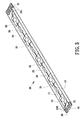
- the light device comprises an inner layer 10, a string of C.O.B. based LED lamps 20, a pair of main wires 30 and 31, and a jacket 40.
- the light device comprises an inner layer 10, a string of C.O.B. based LED lamps 20, a pair of main wires 30 and 31, and a jacket 40.
- the inner layer 10 is a flexible elongate plate-shaped member formed of a transparent (or half-transparent) plastic material.
- the inner layer 10 comprises two parallel upward flanges 12 and 13 on both sides and a lengthwise top groove 11 between the flanges 12 and 13.
- the string of C.O.B. based LED lamps 20 comprises a plurality of units each including a C.O.B. based LED lamp 21 (i.e., C.O.B. based LED lamp 21 mounted on a board), two conductor sections 23 coupled to opposite ends of the C.O.B. based LED lamp 21 by soldering, and a resistor 22 interconnecting the other conductor section 23 of a unit and one conductor section 23 of an adjacent unit by soldering.
- C.O.B. based LED lamps 21 are series connected. Further, the string of C.O.B. based LED lamps 20 are secured on the groove 11 by clinging between the flanges 12 and 13.
- the pair of main wires 30 and 31 are disposed within the flanges 12 and 13.
- a front most conductor section 230 is disposed on the main wire 30 in a front side of the inner layer 10 by a tool.
- a rearmost conductor section 231 is disposed on the main wire 31 in a rear side of the inner layer 10 by a tool.
- the main wires 30 and 31 interconnect a power source (not shown) and the string of C.O.B. based LED lamps 20 to form an electric circuit.
- the jacket 40 having the same plastic material as the inner layer 10, is formed to wrap up the inner layer 10 and the string of C.O.B. based LED lamps 20 by extrusion.
- FIG. 4 specifically, there is shown a side plan view of the light device of the present invention. A smoothness of flat top and bottom surface 41 and 42 of the jacket 40 can be seen clearly. Also, light emitted from the C.O.B. based LED lamp 21 (as indicated by arrow) concentrates in a direction perpendicular to the top surface 41, thus obtaining an increased illumination.
- FIG. 5 specifically, there is shown another embodiment of the jacket 40 of the present invention wherein a plurality of parallel troughs 410 and 420 are formed on the top and bottom surfaces 41 and 42 respectively.
- a process of manufacturing the flexible rod light device of the invention comprises the steps of:
- the benefits of this invention include: the C.O.B. based LED lamps 21 are fastened and have the same orientation. Enhanced flexibility of the conductor sections 23 on the groove 11 (i.e., X-Y plane as assumed) to withstand a pulling of the light device. Protection the resistors 22 against damage. Easy installation is effected due to the flat top and bottom surfaces 41 and 42 of the jacket 40. Light emitted from C.O.B. based LED lamps 21 (as indicated by arrow) can concentrate in a direction perpendicular to the top surface 41, i.e., increased illumination.
- Each unit comprises a C.O.B. based LED lamp 21, a SMD resistor (or current control IC) 22a mounted on the C.O.B. based LED lamp 21 by soldering, and a conductor section 23 coupled between the C.O.B. based LED lamps 21 of two adjacent units by soldering.
- step 2 may be slightly adjusted as the following: form each unit of the string of C.O.B. based LED lamps 20 by passing through a soldering paste or by spot welding on a section of wire of copper foil.
- FIG. 7 there is shown a third preferred embodiment of the invention.
- An elongate copper foil section 24 is used to replace the conductor section for interconnecting the C.O.B. based LED lamps 21 of two adjacent units by soldering.
- SMD resistor (or current control IC) 22a is mounted on a bottom of the C.O.B. based LED lamp 21.
- FIG. 8 there is shown a fourth preferred embodiment of the invention.
- the difference of the third and the fourth embodiments is that the elongate copper foil section 24 is replaced by a conductor section 23a and a flexible sleeve 25 is sleeved on the conductor section 23a.
- a benefit of permitting a pulling of the sleeve 25 without disengaging the conductor section 23a from the adjacent C.O.B. based LED lamp 21 is obtained.
- an enhanced flexibility of the conductor section is achieved.
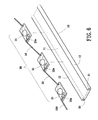
- FIG. 9 there is shown a fifth preferred embodiment of the invention.
- the elongate copper foil section 24 is replaced by an elongate metal foil section 27.
- a temporary tape 26 having a plurality of equally spaced apart rectangular openings 261 (formed by punching) each sized for positioning the C.O.B. based LED lamp 21 and small portions of the elongate metal foil sections 27 therein is provided.
- the tape 26 is removed once the string of C.O.B. based LED lamps 20 has been secured on the groove 11.
- the coupling of the C.O.B. based LED lamp 21 and the elongate metal foil sections 27 may be effected by means of a solder machine having a plurality of soldering means for simultaneous soldering.
- FIG. 10 there is shown a sixth preferred embodiment of the invention.
- a plurality of equally spaced apart rectangular recesses 15 are formed on the groove 11 by punching wherein each recess 15 is sized to receive and secure the C.O.B. based LED lamp 21 therein.
- a plurality of bubbles are formed on top of each recess 15 by controlling extrusion temperature and extrusion speed of the jacket.
- a flexibility of the light device is made possible because the bubbles can provide a buffering effect between the recess 15 and the C.O.B. based LED lamp 21 when the light device is bent.
- a plurality of raised points are formed on top of each recess 15. The raised points also can provide a buffering effect between the recess 15 and the C.O.B. based LED lamp 21 when the light device is bent.
- FIG. 11 there is shown a seventh preferred embodiment of the invention.
- the difference of the fifth and the seventh embodiments is that the tape 26 is secured on top of the inner layer 10 by means of adhesive. Such also can achieve the purpose of positioning and securing the string of C.O.B. based LED lamps 20 on the inner layer 10.
- FIG. 12 there is shown an eighth preferred embodiment of the invention.
- the difference of the seventh and the eighth embodiments are that a plurality of equally spaced apart slots 16 are formed on either side of the groove 11 abutted on the flanges 12 and 13 and a plurality of equally spaced apart latched members 263 are formed on either side of the string of C.O.B. based LED lamps 20 wherein each latched member 263 is inserted into and secure in each corresponding slot 16.
- side surfaces 43 and 44 of the jacket 40 can be made flat. Thus, a substantially rectangular or square cross-section of the light is obtained.
Landscapes
- Engineering & Computer Science (AREA)
- General Engineering & Computer Science (AREA)
- Led Device Packages (AREA)
- Fastening Of Light Sources Or Lamp Holders (AREA)
- Non-Portable Lighting Devices Or Systems Thereof (AREA)
- Illuminated Signs And Luminous Advertising (AREA)
Applications Claiming Priority (2)
| Application Number | Priority Date | Filing Date | Title |
|---|---|---|---|
| CNB021171971A CN100547282C (zh) | 2002-04-25 | 2002-04-25 | 可挠性发光体装置及其制造方法 |
| CN02117197 | 2002-04-25 |
Publications (3)
| Publication Number | Publication Date |
|---|---|
| EP1357331A2 true EP1357331A2 (fr) | 2003-10-29 |
| EP1357331A3 EP1357331A3 (fr) | 2006-04-26 |
| EP1357331B1 EP1357331B1 (fr) | 2008-08-06 |
Family
ID=28680795
Family Applications (1)
| Application Number | Title | Priority Date | Filing Date |
|---|---|---|---|
| EP03252581A Expired - Lifetime EP1357331B1 (fr) | 2002-04-25 | 2003-04-24 | Bande lumineuse flexible comprenant des lampes-diodes du type puce-sur-panneau et procédé de fabrication d'une telle bande |
Country Status (7)
| Country | Link |
|---|---|
| EP (1) | EP1357331B1 (fr) |
| JP (1) | JP3970800B2 (fr) |
| KR (1) | KR100967192B1 (fr) |
| CN (1) | CN100547282C (fr) |
| AT (1) | ATE403827T1 (fr) |
| CA (1) | CA2426500C (fr) |
| DE (1) | DE60322619D1 (fr) |
Cited By (25)
| Publication number | Priority date | Publication date | Assignee | Title |
|---|---|---|---|---|
| WO2006099773A1 (fr) | 2005-03-21 | 2006-09-28 | He Shan Lide Electronic Enterprise Company Ltd. | Lampe tubulaire flexible à effet clignotant circulant |
| US7340830B2 (en) * | 2003-10-28 | 2008-03-11 | Li-Wen Liu | Method of manufacturing LED light string |
| ES2315036A1 (es) * | 2004-07-09 | 2009-03-16 | Lightled, S.A. | Pantalla luminosa. |
| DE102008009808A1 (de) * | 2008-02-19 | 2009-08-27 | Lighting Innovation Group Ag | LED-Lichtleiste höherer Schutzart |
| EP1583147A3 (fr) * | 2004-04-01 | 2009-10-28 | Yuan Lin | Dispositif semiconducteur flexible totalement en couleur pour source de lumière |
| DE102009035369A1 (de) * | 2009-07-30 | 2011-02-03 | Osram Gesellschaft mit beschränkter Haftung | Leuchtmodul, Leuchtband mit mehreren zusammenhängenden Leuchtmodulen und Verfahren zum Konfektionieren eines Leuchtbands |
| WO2011110217A1 (fr) | 2010-03-09 | 2011-09-15 | Tri-O-Light Bv | Bande lumineuse |
| DE102010013286A1 (de) * | 2010-03-29 | 2011-09-29 | Heraeus Noblelight Gmbh | LED-Lampe zur homogenen Ausleuchtung von Hohlkörpern |
| CN101556030B (zh) * | 2008-04-09 | 2012-02-15 | 矽诚科技股份有限公司 | 发光二极管灯串与灯组 |
| CN102588782A (zh) * | 2012-02-01 | 2012-07-18 | 区其富 | 一种led照明装置及应用该照明装置的灯具 |
| CN102644875A (zh) * | 2012-04-05 | 2012-08-22 | 区其富 | 一种照明单元及应用该照明单元的灯具 |
| DE102007017604B4 (de) * | 2006-10-09 | 2012-12-06 | Chang-Gui Liu | Verfahren zur Herstellung einer Lampenreihe |
| US8427048B2 (en) | 2007-03-15 | 2013-04-23 | Sharp Kabushiki Kaisha | Light emitting device and method for manufacturing the same |
| US8496351B2 (en) | 2006-09-12 | 2013-07-30 | Huizhou Light Engine Ltd. | Integrally formed single piece light emitting diode light wire and uses thereof |
| US8651698B2 (en) | 2007-12-21 | 2014-02-18 | 3M Innovative Properties Company | Lighting assemblies and methods of making same |
| US8789971B2 (en) | 2006-09-12 | 2014-07-29 | Huizhou Light Engine Ltd | Integrally formed single piece light emitting diode light wire |
| US8807796B2 (en) | 2006-09-12 | 2014-08-19 | Huizhou Light Engine Ltd. | Integrally formed light emitting diode light wire and uses thereof |
| CN104934515A (zh) * | 2015-06-26 | 2015-09-23 | 浙江亿米光电科技有限公司 | 柔性灯片及其加工工艺应用该灯片的照明装置及制造方法 |
| ITUB20153160A1 (it) * | 2015-08-19 | 2017-02-19 | Osram Spa | Dispositivo di illuminazione e corrispondente procedimento |
| WO2017080705A1 (fr) * | 2015-11-09 | 2017-05-18 | Robert Bosch Gmbh | Unité d'éclairage |
| EP3188264A1 (fr) * | 2016-02-26 | 2017-07-05 | Liquidleds Lighting Corp. | Source lumineuse à diode électroluminescente et lampe |
| EP3392559A4 (fr) * | 2015-12-15 | 2018-10-24 | CRRC Qingdao Sifang Co., Ltd. | Éclairage de véhicule ferroviaire |
| US10408391B2 (en) | 2016-11-30 | 2019-09-10 | Tactotek Oy | Illuminated structure and related method of manufacture |
| US10598314B2 (en) | 2017-03-31 | 2020-03-24 | Liquidleds Lighting Corp. | LED lamp |
| US12293965B2 (en) | 2020-08-03 | 2025-05-06 | Feit Electric Company, Inc. | Omnidirectional flexible light emitting device |
Families Citing this family (29)
| Publication number | Priority date | Publication date | Assignee | Title |
|---|---|---|---|---|
| JP4432703B2 (ja) * | 2004-09-29 | 2010-03-17 | 豊田合成株式会社 | 発光装置の輝度制御方法及び制御データ生成装置 |
| WO2006081707A1 (fr) * | 2005-02-06 | 2006-08-10 | He Shan Lide Electronic Enterprise Company Ltd. | Tube lumineux d'un nouveau type |
| JP2013058771A (ja) * | 2005-10-28 | 2013-03-28 | Proteras Co Ltd | フレキシブル発光体 |
| FR2895781B1 (fr) * | 2005-12-29 | 2014-10-10 | Saint Gobain | Structure lumineuse comportant au moins une diode electroluminescente, sa fabrication et ses applications |
| CN101143251B (zh) * | 2006-09-11 | 2013-09-04 | 林原 | 超薄型逃生指引装置 |
| JP4479839B2 (ja) * | 2007-08-10 | 2010-06-09 | パナソニック電工株式会社 | パッケージおよび半導体装置 |
| CN101825243B (zh) * | 2009-03-06 | 2013-05-08 | 刘昌贵 | 一种制作灯带的方法及灯带 |
| CN101852360B (zh) * | 2009-04-03 | 2012-10-10 | 刘昌贵 | 一种制作灯串的方法、灯串及灯带 |
| DE102009032984B3 (de) * | 2009-07-14 | 2011-03-03 | Osram Gesellschaft mit beschränkter Haftung | Biegbare Leuchtmodule und Verfahren zum Herstellen von biegbaren Leuchtmodulen |
| CN101799135A (zh) * | 2010-02-21 | 2010-08-11 | 迪亚士照明有限公司 | 柔性灯带的制作工艺 |
| US8474998B2 (en) * | 2010-03-08 | 2013-07-02 | Ge Lighting Solutions Llc | Rail and clip mounting for LED modules for fluorescent application replacement |
| JP5442534B2 (ja) * | 2010-06-04 | 2014-03-12 | シャープ株式会社 | 発光装置 |
| CN102401253A (zh) * | 2010-09-13 | 2012-04-04 | 欧司朗有限公司 | 灯条以及制造灯条的方法和模具 |
| DE102010048703B4 (de) | 2010-10-19 | 2015-11-05 | Döllken-Kunststoffverarbeitung Gmbh | Verfahren zum kontinuierlichen Herstellen eines LED-Bandes |
| DE102010048705B4 (de) | 2010-10-19 | 2016-09-29 | Döllken-Weimar Gmbh | Vorrichtung und Verfahren zum kontinuierlichen Herstellen eines LED-Bandes |
| JP5857223B2 (ja) * | 2012-03-14 | 2016-02-10 | パナソニックIpマネジメント株式会社 | コネクタ及びこれを用いた照明装置及びこれを用いた照明器具 |
| KR101281030B1 (ko) * | 2012-09-21 | 2013-07-09 | 백인기 | 엘이디 바 |
| KR101401890B1 (ko) * | 2012-12-06 | 2014-05-29 | 강원대학교산학협력단 | 착탈 가능한 도로 조명 장치 |
| CN104019399A (zh) * | 2014-05-19 | 2014-09-03 | 青岛恒青电器有限公司 | 一种户外灯带 |
| CN104406084B (zh) * | 2014-10-26 | 2018-01-23 | 李乔 | 一种用于装饰的抗拉式led软灯条 |
| CN104456249B (zh) * | 2014-12-01 | 2017-09-12 | 深圳市熠鸿光电科技有限公司 | Led光源模组 |
| CN104565965A (zh) * | 2015-01-21 | 2015-04-29 | 中山市格林曼光电科技有限公司 | 一种led灯带 |
| CN106051510A (zh) * | 2016-06-14 | 2016-10-26 | 深圳市灿升实业发展有限公司 | 新型led柔性线条灯的制作方法及新型led柔性线条灯 |
| KR101980072B1 (ko) * | 2016-10-24 | 2019-05-21 | 이희준 | 반도체 칩 실장용 플렉서블 기판 및 이를 이용한 반도체 패키지 |
| KR20190002000U (ko) | 2018-01-29 | 2019-08-07 | 김준열 | 채널간판용 플렉서블 엘이디 기판 |
| CN112955693B (zh) * | 2018-07-18 | 2023-05-05 | 亮锐有限责任公司 | 具有插入器的柔性发光二极管照明条 |
| CN110792941A (zh) * | 2019-11-13 | 2020-02-14 | 惠州市科利尔照明有限责任公司 | 一种可多方向弯曲的led灯带 |
| US11592166B2 (en) | 2020-05-12 | 2023-02-28 | Feit Electric Company, Inc. | Light emitting device having improved illumination and manufacturing flexibility |
| CN114352956B (zh) | 2021-12-07 | 2022-09-30 | 东莞市欧思科光电科技有限公司 | Led灯带的制造方法 |
Family Cites Families (5)
| Publication number | Priority date | Publication date | Assignee | Title |
|---|---|---|---|---|
| JPH06174497A (ja) * | 1992-12-09 | 1994-06-24 | Toshiba Lighting & Technol Corp | 発光ダイオードアレイおよびメータならびに照明装置 |
| JPH08171833A (ja) * | 1994-12-16 | 1996-07-02 | Tokyo Sensor:Kk | 帯状スイッチ装置 |
| DE19627856A1 (de) * | 1996-07-11 | 1998-01-15 | Happich Fahrzeug & Ind Teile | Beleuchtungsleiste und Verfahren zur Herstellung |
| US5934792A (en) * | 1997-02-24 | 1999-08-10 | Itc, Inc. | Flexible lighting system |
| CA2386226A1 (fr) * | 1999-10-04 | 2001-04-12 | J. Marc Hutchins | Systeme de support du type gorge pour systeme d'eclairage allonge |
-
2002
- 2002-04-25 CN CNB021171971A patent/CN100547282C/zh not_active Expired - Lifetime
-
2003
- 2003-04-21 JP JP2003115889A patent/JP3970800B2/ja not_active Expired - Fee Related
- 2003-04-24 CA CA2426500A patent/CA2426500C/fr not_active Expired - Lifetime
- 2003-04-24 EP EP03252581A patent/EP1357331B1/fr not_active Expired - Lifetime
- 2003-04-24 AT AT03252581T patent/ATE403827T1/de not_active IP Right Cessation
- 2003-04-24 DE DE60322619T patent/DE60322619D1/de not_active Expired - Lifetime
- 2003-04-25 KR KR1020030026305A patent/KR100967192B1/ko not_active Expired - Fee Related
Non-Patent Citations (1)
| Title |
|---|
| None |
Cited By (42)
| Publication number | Priority date | Publication date | Assignee | Title |
|---|---|---|---|---|
| US7340830B2 (en) * | 2003-10-28 | 2008-03-11 | Li-Wen Liu | Method of manufacturing LED light string |
| EP1583147A3 (fr) * | 2004-04-01 | 2009-10-28 | Yuan Lin | Dispositif semiconducteur flexible totalement en couleur pour source de lumière |
| ES2315036A1 (es) * | 2004-07-09 | 2009-03-16 | Lightled, S.A. | Pantalla luminosa. |
| ES2315036B1 (es) * | 2004-07-09 | 2010-01-11 | Lightled, S.A. | Pantalla luminosa. |
| EP1862726A4 (fr) * | 2005-03-21 | 2008-05-14 | He Shan Lide Electronic Entpr | Lampe tubulaire flexible à effet clignotant circulant |
| WO2006099773A1 (fr) | 2005-03-21 | 2006-09-28 | He Shan Lide Electronic Enterprise Company Ltd. | Lampe tubulaire flexible à effet clignotant circulant |
| US8807796B2 (en) | 2006-09-12 | 2014-08-19 | Huizhou Light Engine Ltd. | Integrally formed light emitting diode light wire and uses thereof |
| US8789971B2 (en) | 2006-09-12 | 2014-07-29 | Huizhou Light Engine Ltd | Integrally formed single piece light emitting diode light wire |
| US8496351B2 (en) | 2006-09-12 | 2013-07-30 | Huizhou Light Engine Ltd. | Integrally formed single piece light emitting diode light wire and uses thereof |
| DE102007017604B4 (de) * | 2006-10-09 | 2012-12-06 | Chang-Gui Liu | Verfahren zur Herstellung einer Lampenreihe |
| US9755115B2 (en) | 2007-03-15 | 2017-09-05 | Sharp Kabushiki Kaisha | Light emitting device and method for manufacturing the same |
| US8841838B2 (en) | 2007-03-15 | 2014-09-23 | Sharp Kabushiki Kaisha | Light emitting device and method for manufacturing the same |
| US9966504B2 (en) | 2007-03-15 | 2018-05-08 | Sharp Kabushiki Kaisha | Light emitting device and method for manufacturing the same |
| US9478716B2 (en) | 2007-03-15 | 2016-10-25 | Sharp Kabushiki Kaisha | Light emitting device and method for manufacturing the same |
| US9484502B2 (en) | 2007-03-15 | 2016-11-01 | Sharp Kabushiki Kaisha | Light emitting device and method for manufacturing the same |
| US8427048B2 (en) | 2007-03-15 | 2013-04-23 | Sharp Kabushiki Kaisha | Light emitting device and method for manufacturing the same |
| US8651698B2 (en) | 2007-12-21 | 2014-02-18 | 3M Innovative Properties Company | Lighting assemblies and methods of making same |
| DE102008009808A1 (de) * | 2008-02-19 | 2009-08-27 | Lighting Innovation Group Ag | LED-Lichtleiste höherer Schutzart |
| CN101556030B (zh) * | 2008-04-09 | 2012-02-15 | 矽诚科技股份有限公司 | 发光二极管灯串与灯组 |
| DE102009035369A1 (de) * | 2009-07-30 | 2011-02-03 | Osram Gesellschaft mit beschränkter Haftung | Leuchtmodul, Leuchtband mit mehreren zusammenhängenden Leuchtmodulen und Verfahren zum Konfektionieren eines Leuchtbands |
| US9109765B2 (en) | 2009-07-30 | 2015-08-18 | Osram Gmbh | Lighting module, lighting strip including a plurality of contiguous lighting modules, and method for preparing a lighting strip |
| DE102009035369B4 (de) | 2009-07-30 | 2018-03-22 | Osram Gmbh | Leuchtmodul, Leuchtband mit mehreren zusammenhängenden Leuchtmodulen und Verfahren zum Konfektionieren eines Leuchtbands |
| WO2011110217A1 (fr) | 2010-03-09 | 2011-09-15 | Tri-O-Light Bv | Bande lumineuse |
| DE102010013286B4 (de) * | 2010-03-29 | 2012-03-22 | Heraeus Noblelight Gmbh | LED-Lampe zur homogenen Ausleuchtung von Hohlkörpern |
| DE102010013286A1 (de) * | 2010-03-29 | 2011-09-29 | Heraeus Noblelight Gmbh | LED-Lampe zur homogenen Ausleuchtung von Hohlkörpern |
| US9188289B2 (en) | 2010-03-29 | 2015-11-17 | Heraeus Noblelight Gmbh | LED lamp for homogeneously illuminating hollow bodies |
| CN102588782B (zh) * | 2012-02-01 | 2014-03-05 | 区其富 | 一种led照明装置及应用该照明装置的灯具 |
| CN102588782A (zh) * | 2012-02-01 | 2012-07-18 | 区其富 | 一种led照明装置及应用该照明装置的灯具 |
| CN102644875A (zh) * | 2012-04-05 | 2012-08-22 | 区其富 | 一种照明单元及应用该照明单元的灯具 |
| CN104934515A (zh) * | 2015-06-26 | 2015-09-23 | 浙江亿米光电科技有限公司 | 柔性灯片及其加工工艺应用该灯片的照明装置及制造方法 |
| ITUB20153160A1 (it) * | 2015-08-19 | 2017-02-19 | Osram Spa | Dispositivo di illuminazione e corrispondente procedimento |
| WO2017080705A1 (fr) * | 2015-11-09 | 2017-05-18 | Robert Bosch Gmbh | Unité d'éclairage |
| EP3392559A4 (fr) * | 2015-12-15 | 2018-10-24 | CRRC Qingdao Sifang Co., Ltd. | Éclairage de véhicule ferroviaire |
| US10822001B2 (en) | 2015-12-15 | 2020-11-03 | Crrc Qingdao Sifang Co., Ltd. | Rail vehicle lighting device |
| EP3188264A1 (fr) * | 2016-02-26 | 2017-07-05 | Liquidleds Lighting Corp. | Source lumineuse à diode électroluminescente et lampe |
| US9945532B2 (en) | 2016-02-26 | 2018-04-17 | Liquidleds Lighting Corp. | Light-emitting diode light source and lamp |
| EP3188264B1 (fr) | 2016-02-26 | 2018-07-25 | Liquidleds Lighting Corp. | Source lumineuse à diode électroluminescente et lampe |
| EP3493259A1 (fr) * | 2016-02-26 | 2019-06-05 | Liquidleds Lighting Corp. | Source lumineuse à diode électroluminescente et lampe |
| EP3413361B1 (fr) * | 2016-02-26 | 2020-09-02 | Liquidleds Lighting Corp. | Source lumineuse à diode électroluminescente et lampe |
| US10408391B2 (en) | 2016-11-30 | 2019-09-10 | Tactotek Oy | Illuminated structure and related method of manufacture |
| US10598314B2 (en) | 2017-03-31 | 2020-03-24 | Liquidleds Lighting Corp. | LED lamp |
| US12293965B2 (en) | 2020-08-03 | 2025-05-06 | Feit Electric Company, Inc. | Omnidirectional flexible light emitting device |
Also Published As
| Publication number | Publication date |
|---|---|
| CA2426500A1 (fr) | 2003-10-25 |
| CN100547282C (zh) | 2009-10-07 |
| EP1357331B1 (fr) | 2008-08-06 |
| EP1357331A3 (fr) | 2006-04-26 |
| ATE403827T1 (de) | 2008-08-15 |
| KR100967192B1 (ko) | 2010-07-05 |
| CA2426500C (fr) | 2011-04-05 |
| CN1453498A (zh) | 2003-11-05 |
| DE60322619D1 (de) | 2008-09-18 |
| JP3970800B2 (ja) | 2007-09-05 |
| JP2003347593A (ja) | 2003-12-05 |
| KR20030084759A (ko) | 2003-11-01 |
Similar Documents
| Publication | Publication Date | Title |
|---|---|---|
| US6866398B2 (en) | Flexibe rod light device formed of chip on board based LED lamps and manufacturing method thereof | |
| EP1357331B1 (fr) | Bande lumineuse flexible comprenant des lampes-diodes du type puce-sur-panneau et procédé de fabrication d'une telle bande | |
| US6682205B2 (en) | Flexible rod light and manufacturing method thereof | |
| EP1357330B1 (fr) | Rampe d'éclairage flexible et méthode de fabrication | |
| US7140751B2 (en) | Full-color flexible light source device | |
| JP3862723B2 (ja) | 発光モジュール | |
| US20080239716A1 (en) | Light strip | |
| US11690172B2 (en) | LED lighting systems and methods | |
| US20040007981A1 (en) | Chained led light source structure | |
| EP1583147A2 (fr) | Dispositif semiconducteur flexible totalement en couleur pour source de lumière | |
| EP2373123A2 (fr) | Procédé et structure de voyant miniaturisé | |
| CN109973837B (zh) | 具有稳定的引线框架的led模块 | |
| CA2342440A1 (fr) | Gestion thermique par del | |
| US12016121B2 (en) | Interconnectable circuit boards adapted for three-dimensional constructions as lighting sources | |
| US20130188357A1 (en) | Channel letter lighting system using high output white light emitting diodes | |
| US20100149811A1 (en) | Channel letter lighting system using high output white light emitting diodes | |
| EP1426674A2 (fr) | LED-modules empilables | |
| CN217030932U (zh) | 一种方便安装的磁吸灯带 | |
| JP2025500823A (ja) | 3次元ledのためのled電気接点 | |
| CN110822315B (zh) | 抗弯折柔性灯带 | |
| CN113483282A (zh) | 一种具有倒装led芯片的柔性灯带及其制作方法 | |
| JPH03188609A (ja) | 小型コイルの製造方法 | |
| CN121346194A (zh) | 一种可在任意位置裁剪的灯带 | |
| CN105280271A (zh) | 扁平电缆及其制造方法 | |
| WO2014138464A1 (fr) | Système d'éclairage de lettre boîtier à l'aide de diodes électroluminescentes blanches à rendement élevé |
Legal Events
| Date | Code | Title | Description |
|---|---|---|---|
| PUAI | Public reference made under article 153(3) epc to a published international application that has entered the european phase |
Free format text: ORIGINAL CODE: 0009012 |
|
| AK | Designated contracting states |
Kind code of ref document: A2 Designated state(s): AT BE BG CH CY CZ DE DK EE ES FI FR GB GR HU IE IT LI LU MC NL PT RO SE SI SK TR |
|
| AX | Request for extension of the european patent |
Extension state: AL LT LV MK |
|
| PUAL | Search report despatched |
Free format text: ORIGINAL CODE: 0009013 |
|
| AK | Designated contracting states |
Kind code of ref document: A3 Designated state(s): AT BE BG CH CY CZ DE DK EE ES FI FR GB GR HU IE IT LI LU MC NL PT RO SE SI SK TR |
|
| AX | Request for extension of the european patent |
Extension state: AL LT LV MK |
|
| 17P | Request for examination filed |
Effective date: 20061026 |
|
| AKX | Designation fees paid |
Designated state(s): AT BE BG CH CY CZ DE DK EE ES FI FR GB GR HU IE IT LI LU MC NL PT RO SE SI SK TR |
|
| RIC1 | Information provided on ipc code assigned before grant |
Ipc: F21S 4/00 20060101AFI20080207BHEP Ipc: F21Y 101/02 20060101ALI20080207BHEP |
|
| 17Q | First examination report despatched |
Effective date: 20080225 |
|
| GRAP | Despatch of communication of intention to grant a patent |
Free format text: ORIGINAL CODE: EPIDOSNIGR1 |
|
| GRAS | Grant fee paid |
Free format text: ORIGINAL CODE: EPIDOSNIGR3 |
|
| GRAA | (expected) grant |
Free format text: ORIGINAL CODE: 0009210 |
|
| AK | Designated contracting states |
Kind code of ref document: B1 Designated state(s): AT BE BG CH CY CZ DE DK EE ES FI FR GB GR HU IE IT LI LU MC NL PT RO SE SI SK TR |
|
| REG | Reference to a national code |
Ref country code: GB Ref legal event code: FG4D |
|
| REG | Reference to a national code |
Ref country code: CH Ref legal event code: EP |
|
| REG | Reference to a national code |
Ref country code: IE Ref legal event code: FG4D |
|
| REF | Corresponds to: |
Ref document number: 60322619 Country of ref document: DE Date of ref document: 20080918 Kind code of ref document: P |
|
| PG25 | Lapsed in a contracting state [announced via postgrant information from national office to epo] |
Ref country code: ES Free format text: LAPSE BECAUSE OF FAILURE TO SUBMIT A TRANSLATION OF THE DESCRIPTION OR TO PAY THE FEE WITHIN THE PRESCRIBED TIME-LIMIT Effective date: 20081117 |
|
| PG25 | Lapsed in a contracting state [announced via postgrant information from national office to epo] |
Ref country code: AT Free format text: LAPSE BECAUSE OF FAILURE TO SUBMIT A TRANSLATION OF THE DESCRIPTION OR TO PAY THE FEE WITHIN THE PRESCRIBED TIME-LIMIT Effective date: 20080806 Ref country code: SI Free format text: LAPSE BECAUSE OF FAILURE TO SUBMIT A TRANSLATION OF THE DESCRIPTION OR TO PAY THE FEE WITHIN THE PRESCRIBED TIME-LIMIT Effective date: 20080806 Ref country code: FI Free format text: LAPSE BECAUSE OF FAILURE TO SUBMIT A TRANSLATION OF THE DESCRIPTION OR TO PAY THE FEE WITHIN THE PRESCRIBED TIME-LIMIT Effective date: 20080806 |
|
| PG25 | Lapsed in a contracting state [announced via postgrant information from national office to epo] |
Ref country code: BE Free format text: LAPSE BECAUSE OF FAILURE TO SUBMIT A TRANSLATION OF THE DESCRIPTION OR TO PAY THE FEE WITHIN THE PRESCRIBED TIME-LIMIT Effective date: 20080806 |
|
| PG25 | Lapsed in a contracting state [announced via postgrant information from national office to epo] |
Ref country code: DK Free format text: LAPSE BECAUSE OF FAILURE TO SUBMIT A TRANSLATION OF THE DESCRIPTION OR TO PAY THE FEE WITHIN THE PRESCRIBED TIME-LIMIT Effective date: 20080806 Ref country code: BG Free format text: LAPSE BECAUSE OF FAILURE TO SUBMIT A TRANSLATION OF THE DESCRIPTION OR TO PAY THE FEE WITHIN THE PRESCRIBED TIME-LIMIT Effective date: 20081106 |
|
| PG25 | Lapsed in a contracting state [announced via postgrant information from national office to epo] |
Ref country code: PT Free format text: LAPSE BECAUSE OF FAILURE TO SUBMIT A TRANSLATION OF THE DESCRIPTION OR TO PAY THE FEE WITHIN THE PRESCRIBED TIME-LIMIT Effective date: 20090106 Ref country code: SK Free format text: LAPSE BECAUSE OF FAILURE TO SUBMIT A TRANSLATION OF THE DESCRIPTION OR TO PAY THE FEE WITHIN THE PRESCRIBED TIME-LIMIT Effective date: 20080806 Ref country code: CZ Free format text: LAPSE BECAUSE OF FAILURE TO SUBMIT A TRANSLATION OF THE DESCRIPTION OR TO PAY THE FEE WITHIN THE PRESCRIBED TIME-LIMIT Effective date: 20080806 Ref country code: RO Free format text: LAPSE BECAUSE OF FAILURE TO SUBMIT A TRANSLATION OF THE DESCRIPTION OR TO PAY THE FEE WITHIN THE PRESCRIBED TIME-LIMIT Effective date: 20080806 |
|
| PLBE | No opposition filed within time limit |
Free format text: ORIGINAL CODE: 0009261 |
|
| STAA | Information on the status of an ep patent application or granted ep patent |
Free format text: STATUS: NO OPPOSITION FILED WITHIN TIME LIMIT |
|
| 26N | No opposition filed |
Effective date: 20090507 |
|
| PG25 | Lapsed in a contracting state [announced via postgrant information from national office to epo] |
Ref country code: EE Free format text: LAPSE BECAUSE OF FAILURE TO SUBMIT A TRANSLATION OF THE DESCRIPTION OR TO PAY THE FEE WITHIN THE PRESCRIBED TIME-LIMIT Effective date: 20080806 |
|
| REG | Reference to a national code |
Ref country code: CH Ref legal event code: PL |
|
| PG25 | Lapsed in a contracting state [announced via postgrant information from national office to epo] |
Ref country code: CH Free format text: LAPSE BECAUSE OF NON-PAYMENT OF DUE FEES Effective date: 20090430 Ref country code: SE Free format text: LAPSE BECAUSE OF FAILURE TO SUBMIT A TRANSLATION OF THE DESCRIPTION OR TO PAY THE FEE WITHIN THE PRESCRIBED TIME-LIMIT Effective date: 20081106 Ref country code: LI Free format text: LAPSE BECAUSE OF NON-PAYMENT OF DUE FEES Effective date: 20090430 |
|
| PG25 | Lapsed in a contracting state [announced via postgrant information from national office to epo] |
Ref country code: IE Free format text: LAPSE BECAUSE OF NON-PAYMENT OF DUE FEES Effective date: 20090424 Ref country code: MC Free format text: LAPSE BECAUSE OF NON-PAYMENT OF DUE FEES Effective date: 20090430 |
|
| PG25 | Lapsed in a contracting state [announced via postgrant information from national office to epo] |
Ref country code: GR Free format text: LAPSE BECAUSE OF FAILURE TO SUBMIT A TRANSLATION OF THE DESCRIPTION OR TO PAY THE FEE WITHIN THE PRESCRIBED TIME-LIMIT Effective date: 20081107 |
|
| PG25 | Lapsed in a contracting state [announced via postgrant information from national office to epo] |
Ref country code: LU Free format text: LAPSE BECAUSE OF NON-PAYMENT OF DUE FEES Effective date: 20090424 |
|
| PG25 | Lapsed in a contracting state [announced via postgrant information from national office to epo] |
Ref country code: HU Free format text: LAPSE BECAUSE OF FAILURE TO SUBMIT A TRANSLATION OF THE DESCRIPTION OR TO PAY THE FEE WITHIN THE PRESCRIBED TIME-LIMIT Effective date: 20090207 |
|
| PG25 | Lapsed in a contracting state [announced via postgrant information from national office to epo] |
Ref country code: TR Free format text: LAPSE BECAUSE OF FAILURE TO SUBMIT A TRANSLATION OF THE DESCRIPTION OR TO PAY THE FEE WITHIN THE PRESCRIBED TIME-LIMIT Effective date: 20080806 |
|
| PG25 | Lapsed in a contracting state [announced via postgrant information from national office to epo] |
Ref country code: CY Free format text: LAPSE BECAUSE OF FAILURE TO SUBMIT A TRANSLATION OF THE DESCRIPTION OR TO PAY THE FEE WITHIN THE PRESCRIBED TIME-LIMIT Effective date: 20080806 |
|
| PG25 | Lapsed in a contracting state [announced via postgrant information from national office to epo] |
Ref country code: IT Free format text: LAPSE BECAUSE OF NON-PAYMENT OF DUE FEES Effective date: 20130424 |
|
| PGFP | Annual fee paid to national office [announced via postgrant information from national office to epo] |
Ref country code: IT Payment date: 20140430 Year of fee payment: 11 |
|
| PGRI | Patent reinstated in contracting state [announced from national office to epo] |
Ref country code: IT Effective date: 20140701 |
|
| PGRI | Patent reinstated in contracting state [announced from national office to epo] |
Ref country code: IT Effective date: 20140701 |
|
| REG | Reference to a national code |
Ref country code: FR Ref legal event code: PLFP Year of fee payment: 14 |
|
| REG | Reference to a national code |
Ref country code: FR Ref legal event code: PLFP Year of fee payment: 15 |
|
| REG | Reference to a national code |
Ref country code: FR Ref legal event code: PLFP Year of fee payment: 16 |
|
| PGFP | Annual fee paid to national office [announced via postgrant information from national office to epo] |
Ref country code: NL Payment date: 20190429 Year of fee payment: 17 |
|
| PGFP | Annual fee paid to national office [announced via postgrant information from national office to epo] |
Ref country code: FR Payment date: 20190430 Year of fee payment: 17 |
|
| PGFP | Annual fee paid to national office [announced via postgrant information from national office to epo] |
Ref country code: GB Payment date: 20190902 Year of fee payment: 17 |
|
| PGFP | Annual fee paid to national office [announced via postgrant information from national office to epo] |
Ref country code: DE Payment date: 20191029 Year of fee payment: 17 |
|
| REG | Reference to a national code |
Ref country code: DE Ref legal event code: R119 Ref document number: 60322619 Country of ref document: DE |
|
| REG | Reference to a national code |
Ref country code: NL Ref legal event code: MM Effective date: 20200501 |
|
| PG25 | Lapsed in a contracting state [announced via postgrant information from national office to epo] |
Ref country code: FR Free format text: LAPSE BECAUSE OF NON-PAYMENT OF DUE FEES Effective date: 20200430 Ref country code: DE Free format text: LAPSE BECAUSE OF NON-PAYMENT OF DUE FEES Effective date: 20201103 |
|
| GBPC | Gb: european patent ceased through non-payment of renewal fee |
Effective date: 20200424 |
|
| PG25 | Lapsed in a contracting state [announced via postgrant information from national office to epo] |
Ref country code: NL Free format text: LAPSE BECAUSE OF NON-PAYMENT OF DUE FEES Effective date: 20200501 |
|
| PG25 | Lapsed in a contracting state [announced via postgrant information from national office to epo] |
Ref country code: GB Free format text: LAPSE BECAUSE OF NON-PAYMENT OF DUE FEES Effective date: 20200424 |