EP1358945B2 - Düsenanordnung für eine Vorrichtung zum Auftragen von fliessfähigem Material auf ein Substrat - Google Patents
Düsenanordnung für eine Vorrichtung zum Auftragen von fliessfähigem Material auf ein Substrat Download PDFInfo
- Publication number
- EP1358945B2 EP1358945B2 EP03017309A EP03017309A EP1358945B2 EP 1358945 B2 EP1358945 B2 EP 1358945B2 EP 03017309 A EP03017309 A EP 03017309A EP 03017309 A EP03017309 A EP 03017309A EP 1358945 B2 EP1358945 B2 EP 1358945B2
- Authority
- EP
- European Patent Office
- Prior art keywords
- substrate
- liquid
- mouthpiece
- valve body
- supply channel
- Prior art date
- Legal status (The legal status is an assumption and is not a legal conclusion. Google has not performed a legal analysis and makes no representation as to the accuracy of the status listed.)
- Expired - Lifetime
Links
- 239000000758 substrate Substances 0.000 title claims description 73
- 239000000463 material Substances 0.000 title description 57
- 230000009969 flowable effect Effects 0.000 title description 6
- 239000007788 liquid Substances 0.000 claims description 13
- 238000009825 accumulation Methods 0.000 claims description 4
- 238000011144 upstream manufacturing Methods 0.000 claims description 2
- 239000011344 liquid material Substances 0.000 claims 3
- 239000012530 fluid Substances 0.000 claims 2
- 239000011248 coating agent Substances 0.000 claims 1
- 238000000576 coating method Methods 0.000 claims 1
- 239000000853 adhesive Substances 0.000 description 27
- 230000001070 adhesive effect Effects 0.000 description 27
- 230000000712 assembly Effects 0.000 description 8
- 238000000429 assembly Methods 0.000 description 8
- 239000010408 film Substances 0.000 description 4
- 230000000694 effects Effects 0.000 description 2
- 238000002474 experimental method Methods 0.000 description 2
- 239000004831 Hot glue Substances 0.000 description 1
- 230000001154 acute effect Effects 0.000 description 1
- 239000011888 foil Substances 0.000 description 1
- 230000001105 regulatory effect Effects 0.000 description 1
- 125000006850 spacer group Chemical group 0.000 description 1
- 239000010409 thin film Substances 0.000 description 1
Images


Classifications
-
- B—PERFORMING OPERATIONS; TRANSPORTING
- B05—SPRAYING OR ATOMISING IN GENERAL; APPLYING FLUENT MATERIALS TO SURFACES, IN GENERAL
- B05C—APPARATUS FOR APPLYING FLUENT MATERIALS TO SURFACES, IN GENERAL
- B05C5/00—Apparatus in which liquid or other fluent material is projected, poured or allowed to flow on to the surface of the work
- B05C5/02—Apparatus in which liquid or other fluent material is projected, poured or allowed to flow on to the surface of the work the liquid or other fluent material being discharged through an outlet orifice by pressure, e.g. from an outlet device in contact or almost in contact, with the work
- B05C5/027—Coating heads with several outlets, e.g. aligned transversally to the moving direction of a web to be coated
- B05C5/0275—Coating heads with several outlets, e.g. aligned transversally to the moving direction of a web to be coated flow controlled, e.g. by a valve
-
- B—PERFORMING OPERATIONS; TRANSPORTING
- B05—SPRAYING OR ATOMISING IN GENERAL; APPLYING FLUENT MATERIALS TO SURFACES, IN GENERAL
- B05C—APPARATUS FOR APPLYING FLUENT MATERIALS TO SURFACES, IN GENERAL
- B05C5/00—Apparatus in which liquid or other fluent material is projected, poured or allowed to flow on to the surface of the work
- B05C5/02—Apparatus in which liquid or other fluent material is projected, poured or allowed to flow on to the surface of the work the liquid or other fluent material being discharged through an outlet orifice by pressure, e.g. from an outlet device in contact or almost in contact, with the work
- B05C5/0225—Apparatus in which liquid or other fluent material is projected, poured or allowed to flow on to the surface of the work the liquid or other fluent material being discharged through an outlet orifice by pressure, e.g. from an outlet device in contact or almost in contact, with the work characterised by flow controlling means, e.g. valves, located proximate the outlet
- B05C5/0237—Fluid actuated valves
-
- B—PERFORMING OPERATIONS; TRANSPORTING
- B05—SPRAYING OR ATOMISING IN GENERAL; APPLYING FLUENT MATERIALS TO SURFACES, IN GENERAL
- B05C—APPARATUS FOR APPLYING FLUENT MATERIALS TO SURFACES, IN GENERAL
- B05C5/00—Apparatus in which liquid or other fluent material is projected, poured or allowed to flow on to the surface of the work
- B05C5/02—Apparatus in which liquid or other fluent material is projected, poured or allowed to flow on to the surface of the work the liquid or other fluent material being discharged through an outlet orifice by pressure, e.g. from an outlet device in contact or almost in contact, with the work
- B05C5/0254—Coating heads with slot-shaped outlet
Definitions
- the present invention relates to an applicator device according to the preamble of claim 1.
- Such an application device of the type mentioned is z. B. from the EP-A-0 329 829 and from US 3,854,631 known.
- Such a device for applying flowable material to a movable substrate in particular for the intermittent application of liquid adhesive, for example, used to coat film-shaped substrates with liquid adhesive, such as hot melt adhesive, surface.
- Such application devices are often provided with at least one feed channel for supplying flowable material, at least one nozzle arrangement with at least one outlet channel connected to the feed channel and opening into an outlet opening for dispensing material and with a valve arrangement for interrupting the flow of material, a movable valve body and a Valve seat, wherein the valve body cooperates with the valve seat such that the material flow is interrupted by movement of the valve body in a closed position and released into an open position.
- a so-called intermittent order is made, i.
- intervals in which the valve body is in the open position and material is applied to the substrate alternate with intervals in which the valve body is in the closed position, so that the material application is interrupted.
- intermittent order very short intervals are often realized in order to realize order zones with small distances to each other.
- the flow of material must be interrupted up to 1000 times per minute in some applications.
- the request pattern created on the substrate is made the requirement that a material application zone on the substrate has sharply delimited edges.
- a material application zone on the substrate has sharply delimited edges.
- Prior art nozzle assemblies e.g. B. EP 0 329 829
- have a substantially straight contact portion which establishes contact between the nozzle assembly and the substrate.
- the disadvantage here is that it can come to material accumulation between the nozzle assembly and the substrate. This can result in fuzzy boundary lines at the application zones on the substrate.
- the present invention has for its object to provide an application device of the type mentioned, can be made with the sharply defined material application zones on a substrate.
- the object is achieved with an application device according to claim 1.
- Such an applicator device ensures that a substrate in contact with the contact area is always optimally guided to the outlet opening of the nozzle arrangement.
- an optimal alignment of the substrate is always realized relative to the outlet opening.
- the film-like substrate is pressed by means of rollers with a (small) contact pressure against the contact area of the nozzle assembly.
- the substrate is not exactly arranged in a plane, but may have a slightly curved course. Such a curved course in the prior art devices having a substantially straight contact portion results in material accumulation between the nozzle assembly and the substrate.
- the contact region extends, starting from the outlet opening, counter to the direction of movement of the substrate.
- a previously described guidance of the film is thus realized.
- the curved portion is formed partially circular in cross section. In this way, a cheap guide can be realized in a structurally simple manner.
- the application behavior can be optimized according to the invention in that a tear-off edge is formed in the direction of movement of the substrate, just behind the outlet opening, at which the substrate comes out of contact with the contact section on its path of movement. In this way it can be prevented that accumulates material between the substrate - in the form of a film - and the lower portion of the nozzle assembly, which prevents a clean, sharply limited application of adhesive.
- the nozzle arrangement is designed as a slot nozzle arrangement in which the feed channel for the material opens via the channel of the mouthpiece receiver into a distributor channel, to which at least one outlet channel with a slot-shaped outlet opening is connected downstream.
- the outer contact area extends from the exit opening in a direction opposite to the direction of application of the workable material to the substrate.
- the invention is advantageously further developed in that a straight through-bore is formed in the mouthpiece receptacle as a channel for supplying material in the distribution channel, which is fed with material from the supply channel and whose lower outlet opening opens into the distribution channel.
- the through-hole is arranged obliquely in relation to a main surface of the substrate during operation.
- This embodiment can be further developed in that the longitudinal axis of the through-hole forms an angle of approximately 45 ° with the main surface of the substrate.
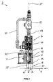
- the device shown for the application of liquid adhesive to a relative to the device in the direction of the arrow shown movable substrate 1 has an applicator head 2.
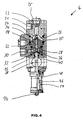
- the upper part of the applicator head 2 comprises an electro-pneumatically actuable control part 4 (see. Fig. 4 ) mounted on a base 6.
- a nozzle assembly 8 is mounted on the underside of the base 6.
- the base 6 is in turn mounted on a stationary carrier, not shown.
- the control part 4 is connected by means of two compressed air lines 10, 11 to a compressed air source, not shown, which provides approximately a pressure of 6 bar. With the help of a solenoid valve 12, the control part 4 can be acted upon with compressed air.
- the base 6 is formed with a bore 7 into which a lower portion of the control part 4 is inserted.
- In the base 6 are in the upper part of two connecting holes 21, 23, which can be selectively connected to a compressed air line.
- the bore 23 is closed with a plug 25.
- valve assembly essentially comprises a valve body 14, a rod-shaped shank portion 16 connected thereto, and a valve seat 44.
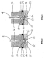
- the valve body 14 cooperates with the valve seat 44 such that material flow is achieved by movement of the valve body 14 is interrupted in a closed position and released by movement in an open position. The valve body 14 comes into contact with the valve seat by movement against the flow direction of the material to interrupt the flow of material.
- a differential pressure piston 18 is attached to the upper movable shaft portion 16.
- the piston 18 is arranged axially displaceably in a bore 20 in a base body 22.
- the piston 18 is formed with a central bore 20 in which a part of the shaft portion 16 is arranged.
- a nut 24 is screwed, which secures the piston 18 to the shaft portion 16.
- a gas-filled space 26 is provided, which is acted upon by gas pressure. As a result, a force can be applied to the piston 18.
- a further gas-filled space 28 is formed within the bore 20 in the base body 22, which is acted upon by means of a connection channel 30 through the line with compressed air 10.
- the piston 18 has an upper active surface 34, which is larger than a lower active surface 36, so that at the same pressure in the spaces 26 and 30, different forces acting on the piston 18 act.
- the piston would - in Fig. 4 down - are pressed in the direction of the nozzle assembly 8, so that the valve body 14 is pressed into its open position.
- the piston 18 is sealed in a manner not described in detail with O-rings relative to the base body 22.
- a spiral spring 32 is arranged, which acts with its spring force on the piston 18 and this - in Fig. 4 upwards - biased in the closed position of the valve assembly.
- the solenoid valve 12 (FIG. Fig. 1 ) open.
- a pressure is generated in the space 26 which corresponds approximately to that of the compressed air source and which acts on the active surface 34.
- the pressure of the compressed air source prevails throughout.
- the piston 18 is moved in the direction of the substrate 1.
- the solenoid valve 12 is switched so that the pressure in the space 26 is reduced.
- compressed air is discharged from the solenoid valve 12 to the environment.
- the piston 18 is pressed by the force acting on the effective surface 36 resulting force "up” and the valve body 14 is moved to the closed position.
- the spring force of the spring 32 supports.
- the shaft portion 16 of the valve 14 has a notch 38 as a mark, which is visible from the outside through a viewing window 40 in the control part 4, so that the position of the movable, attached to the shaft portion 16 valve body 14 is externally visible.
- an adhesive feed channel 46 is formed in a lower portion of the control member 4 which can be fed by means of a connector 48 with adhesive from an adhesive source ,
- the feed channel 46 is formed substantially as a cylindrical bore within a (ring) body 50.
- a ring 52 is fixed, which is also provided with a central through-hole which is part of the feed channel 46.
- valve seat 44 is formed in the FIGS. 2 and 3 is shown as an annular edge.
- the valve seat 44 may be adapted to the shape of the valve body 14. It can be sanded and hardened.
- O-ring 54 of the ring 52 is realtiv sealed to the base 6.
- the valve body 14 is disposed within a substantially cylindrical space 56 formed in the base 6. The space 56 is followed in the flow direction by a passage 58, can flow through the adhesive into the nozzle assembly 8.
- the integrally formed with the shaft portion 16 valve body 14 is formed as well as the shaft portion 16 rotationally symmetrical and has a subsequent to the shaft portion 16 frusto-conical portion 60 which is in contact with the valve seat 44 in the closed position, as in Fig. 3 is shown.
- the section 60 is followed downstream by a substantially circular disk-shaped portion 62 which further downstream in a turn frusto-conical portion 64 which marks the lower end of the body 14.
- the body 14 initially has a widening cross section, then a constant cross section and further downstream a tapering cross section. It has an outer diameter which is greater than the inner diameter of the feed channel 46, so that upon movement of the shaft portion 16 together with the valve body 14 latter comes to rest on the valve seat 44.
- the diameter of the shaft portion 16 is less than that of the feed channel 46, so that an annular channel is formed between the two.
- valve body 14 may be formed substantially as a ball or disc, which is attached to the shaft portion 16, preferably formed integrally therewith.
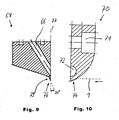
- a passage opens into a channel 66 formed inside the nozzle arrangement 8 which is designed as a slot nozzle arrangement, which channel is formed in an in Fig. 9 illustrated mouthpiece receptacle 68 is formed as a straight through hole.
- the channel 66 is disposed obliquely relative to a vertical axis.
- a mouthpiece 70 mounted separately in Fig. 10 is shown and screwed by means of a bore 71 arranged bolt on the mouthpiece receptacle 68. I'm mounted in Fig.
- FIG. 1 illustrated state opens an elliptical lower opening of the inclined channel 66 in a horizontally disposed in operation distribution channel 72, in which the adhesive is passed into a plurality of outlet channels, not shown, arranged in a conventional manner by means of a between the mouthpiece receptacle 66 and the mouthpiece 70 Spacer plates are formed.
- the outlet channels are formed as elongated slots and open at a lower end of the nozzle assembly 8 (FIG. Fig. 1 ) into slit-shaped outlet openings, from which material can be dispensed.
- the nozzle arrangement 8 has an outer contact area 74, which is in contact with the substrate moving at least in part relative to the outlet opening during the application and which is arranged on the mouthpiece 70.
- the contact region 74 has, as from the Fig. 1 and 10 it can be seen, a relative to the substrate 1 diverging, curved portion. It extends from an exit opening opposite to the direction of movement of the substrate 1 - in Fig. 1 to the left - and is in cross section ( Fig. 10 ) formed part-circular.
- the substrate is flat and lies against the contact region 74, it may however have a slightly curved course, for example if it is designed as a foil guided by rollers.
- the moving substrate 1 is guided from the curved portion of the contact area 74 to the exit opening or the plurality of exit openings of the slot nozzle arrangement arranged in juxtaposition to one another, as in FIG Fig. 10 is indicated by a dashed line. If the outlet opening of the nozzle arrangement during operation is not aligned exactly relative to the substrate 1, for example because the substrate is not guided by a guide device exactly on a desired path or because the entire application head 2 is not exactly located in a desired position on the carrier, then Substrate from the contact portion also guided to the outlet opening.
- the nozzle arrangement 8 has a tear-off edge 76 which is arranged on the mouthpiece receptacle 68.
- the tear-off edge runs an edge 79 of the mouthpiece receptacle 68 in an opposite to an axis 77 (and thus in the Fig. With respect to a vertical axis) acute angle.
- the angle between the edge 79 and the axis 77 is about 20 °.
- FIGS. 5 and 6 show an alternative embodiment of a device according to the invention for applying flowable material, in which two previously described with reference to Fig. 1 to 4 described application heads 78, 80 attached to a base 82 and are arranged substantially perpendicular to each other.
- the device thus has two supply channels which supply a common nozzle arrangement 84 with adhesive.
- the two valve arrangements of the application heads 78 and 80 are controlled electro-pneumatically by means of a control device 77.
- the nozzle assembly 84 has, as previously with reference to FIGS FIGS. 9 and 10 described, a mouthpiece receptacle 86 and attached to this mouthpiece 88.
- the mouthpiece 88 is formed with a curved contact region 74 which at least partially engages a substrate.
- the two valve arrangements of the application heads 78, 80 are controllable such that in a first operating state both valve assemblies release the feed channel 46 for a material flow at the same time and in a second operating state the valve arrangements alternately release or close the respective feed channel 46. In this way, either an alternately intermittent operation of the two guns 78, 80 or a simultaneous flow of material through both guns 78, 80 can be realized. If the two feed channels 46 are fed from different material sources (not shown), during the first operating state the two materials originating from the different material sources can be mixed with one another and applied to a substrate or alternately apply the different materials in the second operating state.
- Fig. 7 shows a part of the application head 78 and the control device 77 and compressed air lines 90, 92, through which the control part for moving the valve body 14 can be acted upon with compressed air.
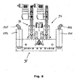
- FIG. 8 Figure 5 shows another alternate embodiment of a flowable material applicator having two guns 94, 96 arranged in parallel and feeding a slot nozzle assembly 98 with material.
- the applicator heads 94, 96 of this device are formed substantially identical, as the basis of the Fig. 1 - 4th described application head 2, and are controllable in the same way as previously with reference to the Fig. 5-7 described device, so that reference is made to the above description.
- By means of two ports 100, 102 and two adhesive filters 104, 106 is adhesive to two terminals 48 in the control part 4 (see. Fig. 4 ).
- the adhesive streams are independent of each other by means of two individually controllable valve arrangements of the applicator heads 94, 96 way described controllable and feed the common slot nozzle assembly 98th
- liquid adhesive or other flowable material by means of supply lines (not shown) in a gun 2, introduced and introduced into the feed channel 46 of a control part 4.
- the material flows into the nozzle assembly 8, there through the obliquely formed in the mouthpiece receiver 68 channel 66 in the substantially horizontal distribution channel 72 in the mouthpiece 70.
- the material is distributed in the distribution channel 72 on a plurality of slot-shaped outlet channels and flows toward the plurality of slit-shaped exit openings at the lower end of the nozzle assembly 8 to be discharged therefrom and applied to the moving substrate 1.
- the substrate may be a thin film of plastic, which is guided by means of several rollers.
- the substrate lies substantially in one plane and is in contact with the contact region 74, more precisely with a part of the curved portion of the contact region 74.
- the nozzle assembly 8 is formed as a slot nozzle arrangement for a flat application, it could also be formed as a nozzle assembly whose outlet openings have other shapes.
- the application heads can be controlled with the aid of the control device 77 such that a continuous or discontinuous intermittent material application is made to the substrate.
- the valve body 14 can be opened or closed up to about 1200 times during one minute.
- the piston 18 In intermittent operation, the piston 18 is acted upon by the lines 10, 11, 90, 92 with compressed air, which can be provided in the spaces 26 and 28 with varying pressures.
- the piston 18 In the open position of the valve body 14, the piston 18 by a force acting in the direction of the substrate 1 downward force in the in Fig. 2 pressed position shown.
- the solenoid valve 12 Fig. 1
- compressed air acts on the piston 18. Since the effective area 34 is greater than the effective area 36, the piston is moved in the direction of the substrate 1.
- the force of the spring 32 acts on the piston 18 on the one hand, and at the same time generates a force in the same direction, the size of which can be calculated essentially as the product of pressure and effective area 36.
- the piston 18 is now moved upwardly together with the shaft portion 16, so that the valve body 14 is moved toward the valve seat 44 until it is in contact with the valve body 44, as in Fig. 3 is shown.
- valve body 14 By the movable arrangement of the valve body 14, this acts within the cylindrical space 56 during the closing movement in the manner of a piston disposed within a cylinder and generates a pressure reduction in the cylindrical space 56. Further adhesive adheres to the surface of the valve body 14, so that the adhering Material together with the opposite to the flow direction of the material during the material application moving valve body 14 is "pulled" up.
- valve assemblies of the two guns can be controlled with the aid of the control device that the valve assemblies alternately enable or close the supply channel for a material flow, so that a job image can be produced on the substrate 1, which has very small gaps between individual application zones and small widths of the application zones depending on a predetermined speed of the substrate 1. This may be desirable, for example, if the integral substrate 1 during the application is to be separated later into several parts, each of which is provided with a defined zone with material application.
- the device can be switched by means of the control device in such a way that both application heads have simultaneously opened valve arrangements, so that material flows through both supply channels is conveyed to the outlet openings (or an outlet opening) and applied. If one of the two valve assemblies is brought into the closed position, in which the material flow is interrupted by the supply channel, while the other valve assembly remains in the open position, as compared to the operating condition in which both valve assemblies are in the open position, a lesser material leakage through the opening (or outlet). If one valve arrangement is operated continuously and the other is operated intermittently, an application pattern can be produced on the substrate 1, which zone has stronger and lower application on the substrate.
Landscapes
- Coating Apparatus (AREA)
Description
- Die vorliegende Erfindung betrifft eine Auftragsvorrichtung nach dem Oberbegriff des Anspruchs 1.
- Eine solche Auftragsvorrichtung der eingangs genannten Art ist z. B. aus der
EP-A-0 329 829 und ausUS 3,854,631 bekannt. - In der Industrie wird eine derartige Vorrichtung zum Auftragen von fließfähigem Material auf ein bewegbares Substrat, insbesondere zum intermittierenden Auftragen von flüssigem Klebstoff beispielsweise eingesetzt, um folienförmige Substrate mit flüssigem Klebstoff, etwa Heißschmelzkleber, flächig zu beschichten. Solche Auftragsvorrichtungen sind oft versehen mit mindestens einem Zuführkanal zum Zuführen von fließfähigem Material, mindestens einer Düsenanordnung mit mindestens einem mit dem Zuführkanal verbundenen und in eine Austrittsöffnung zum Abgeben von Material mündenden Austrittskanal sowie mit einer Ventilanordnung zum Unterbrechen des Materialflusses, die einen bewegbaren Ventilkörper sowie einen Ventilsitz aufweist, wobei der Ventilkörper mit dem Ventilsitz derart zusammenwirkt, dass der Materialfluss durch Bewegung des Ventilkörpers in eine Schließstellung unterbrochen und in eine Öffnungsstellung freigegeben wird. Häufig wird ein sogenannter intermittierender Auftrag vorgenommen, d.h. dass Intervalle, in denen der Ventilkörper in der Öffnungsstellung ist und Material auf das Substrat aufgetragen wird, sich mit Intervallen abwechseln, in denen der Ventilkörper in der Schließstellung ist, so dass der Materialauftrag unterbrochen ist. Beim intermittierenden Auftrag werden häufig sehr kurze Intervalle verwirklicht, um Auftragszonen mit geringen Abständen zueinander realisieren zu können. Der Materialfluss muss bei manchen Anwendungen bis zu 1000 Mal pro Minute unterbrochen werden.
- An das auf dem Substrat entstehende Auftragsmuster wird die Anforderung gestellt, dass eine Materialauftragszone auf dem Substrat scharf begrenzte Ränder aufweist. Im Falle eines flächigen Auftrags mit Hilfe einer bekannten Schlitzdüsenanordnung ist es insbesondere erwünscht, dass die - in Bewegungsrichtung des Substrats relativ zur Auftragsvorrichtung - seitlichen Ränder, aber auch die vorderen und hinteren Ränder einer Materialauftragszone scharf begrenzt sind.
- Düsenanordnungen nach dem Stand der Technik, z. B.
EP 0 329 829 , haben einen im Wesentlichen geraden Kontaktabschnitt, der den Kontakt zwischen Düsenanordnung und Substrat herstellt. Nachteilig ist hierbei, dass es zwischen der Düsenanordnung und dem Substrat zu Materialansammlungen kommen kann. Hieraus können unscharfe Begrenzungslinien an den Auftragszonen auf dem Substrat entstehen. - Der vorliegenden Erfindung liegt die Aufgabe zugrunde, eine Auftragsvorrichtung der eingangs genannten Art anzugeben, mit der scharf begrenzte Materialauftragszonen auf einem Substrat hergestellt werden können.
- Die Aufgabe wird mit einer Auftragsvorrichtung gemäß Anspruch 1 gelöst.
- Mit einer derartigen Auftragsvorrichtung wird gewährleistet, dass ein mit dem Kontaktbereich in Berührung stehendes Substrat stets optimal zu der Austrittsöffnung der Düsenanordnung geführt wird. Speziell in dem Fall, in dem ein flexibles, folienartiges Substrat mit Material flächig mit Hilfe einer Schlitzdüsenanordnung beschichtet werden soll, wird stets eine optimale Ausrichtung des Substrats relativ zur Austrittsöffnung verwirklicht. In diesem Fall kommt es regelmäßig dazu, dass das folienartige Substrat mit Hilfe von Rollen mit einer (geringen) Anpresskraft an den Kontaktbereich der Düsenanordnung angepresst wird. Dabei ist das Substrat nicht exakt in einer Ebene angeordnet, sondern kann einen leicht gekrümmten Verlauf aufweisen. Ein derartiger gekrümmter Verlauf hat bei den aus dem Stand der Technik bekannten Vorrichtungen, die einen im wesentlichen geraden Kontaktabschnitt aufweisen, zur Folge, dass es zwischen der Düsenanordnung und dem Substrat zu Materialansammlungen kommen kann. Wird nun die Strömung im intermittierenden Betrieb ständig unterbrochen und wieder freigegeben, so können die Materialansammlungen dazu führen, dass unscharfe Begrenzungslinien an den Auftragszonen auf dem Substrat entstehen. Mit Hilfe des gekrümmten, relativ zum Substrat divergierenden Abschnitts des äußeren Kontaktbereichs wird eine sich bewegende Folie exakt zu der Austrittsöffnung geführt. Zwischenräume, in denen sich Material in unerwünschter Weise ansammeln kann, werden erfindungsgemäß vermieden. Ferner können Beschädigungen des folienartigen Substrates durch den gekrümmten Verlauf vermieden werden.
- Der Kontaktbereich erstreckt sich ausgehend von der Austrittsöffnung entgegen der Bewegungsrichtung des Substrats. Im Einlaufbereich einer Folie in Bewegungsrichtung vor der Austrittsöffnung wird somit eine zuvor beschriebene Führung der Folie realisiert.
- Gemäß einer Weiterbildung der Erfindung ist der gekrümmte Abschnitt im Querschnitt teilkreisförmig ausgebildet. Auf diese Weise lässt sich eine günstige Führung auf konstruktiv einfache Weise realisieren.
- Das Auftragsverhalten lässt sich gemäß der Erfindung dadurch optimieren, dass in Bewegungsrichtung des Substrats dicht hinter der Austrittsöffnung eine Abrisskante ausgebildet ist, an der das Substrat auf seiner Bewegungsbahn außer Berührung von dem Kontaktabschnitt kommt. Auf diese Weise kann verhindert werden, dass sich zwischen dem Substrat - in Form einer Folie - und dem unteren Abschnitt der Düsenanordnung Material ansammelt, das einen sauberen, scharf begrenzten Klebstoffauftrag verhindert.
- Die erfindungsgemäßen Wirkungen werden besonders deutlich, wenn die Düsenanordnung als Schlitzdüsenanordnung ausgebildet ist, bei der der Zuführkanal für das Material über den Kanal der Mundstückaufnahme in einen Verteilerkanal mündet, an dem stromabwärts mindestens ein Austrittskanal mit einer schlitzförmigen Austrittsöffnung angeschlossen ist. Der äußere Kontaktbereich erstreckt sich dabei von der Austrittsöffnung in eine Richtung, die der Richtung der Auftragung des fleißfähigen Materials auf das Substrat entgegengesetzt ist.
- Die Erfindung wird in vorteilhafter Weise weitergebildet, indem in der Mundstückaufnahme eine gerade Durchgangsbohrung als Kanal zum Zuführen von Material in dem Verteilerkanal ausgebildet ist, die von dem Zuführkanal mit Material gespeist wird und deren untere Austrittsöffnung in den Verteilerkanal mündet. In strömungstechnisch besonders günstiger Weise ist die Durchgangsbohrung im Betrieb schräg gegenüber einer Haupt-Oberfläche des Substrats angeordnet. Auf diese Weise können - im Stand der Technik häufig vorhandene - komplizierte Bohrungssysteme innerhalb der Düsenanordnung vermieden werden, bei der häufig Sacklöcher innerhalb der Mundstückaufnahme ausgebildet sind, in denen "Toträume" in bezug auf die Strömung des Materials vorhanden sind, die einen sauberen Klebstoffauftrag insbesondere im intermittierenden Betrieb entgegenwirken. Dieses ist darauf zurückzuführen, dass aufgrund der schrägen Anordnung der Durchgangsbohrung ein minimierter Strömungsweg in der Mundstückaufnahme ausgebildet ist. Während der im intermittierenden Betrieb in der Strömung auftretenden Druckschwankungen ist somit ein minimales Materialvolumen vorhanden, das aufgrund dieser Druckschwankungen komprimiert und expandiert wird, was zu einem nicht abrupten Unterbrechen des Auftrags führt. Durch minimale Strömungswege kann dieser störende Effekt verringert werden.
- Diese Ausführungsform kann dahingehend weitergebildet werden, dass die Längsachse der Durchgangsbohrung einen Winkel von ungefähr 45 ° mit der Haupt-Oberfläche des Substrats bildet.
- Die Erfindung wird nachfolgend anhand von mehreren Ausführungsbeispielen der erfindungsgemäßen Vorrichtung unter Bezugnahme auf die beiliegenden Zeichnungen beschrieben. Es zeigen:
- Fig. 1
- eine Vorrichtung zum Auftragen von flüssigem Klebstoff auf ein Substrat mit einem Auftragskopf in einer Teilschnittsdarstellung, an die eine erfindungsgemäße Düsenanordnung montierbar ist;
- Fig. 2
- eine Schnittdarstellung eines Teils einer Ventitanordnung der Vorrichtung aus
Fig. 1 in geöffneter Stellung; - Fig. 3
- den in
Fig. 2 dargestellter Abschnitt in einer geschlossenen Stellung; - Fig. 4
- ein Steuerteil der in
Fig. 1 dargestellten Vorrichtung in einer Schnittdarstellung; - Fig. 5
- eine Seitenansicht einer Vorrichtung zum Auftragen von Klebstoff mit zwei Auftragsköpfen und zwei Ventilanordnungen;
- Fig. 6
- eine Teilschnittdarstellung der Vorrichtung aus
Fig. 5 ; - Fig. 7
- eine vergrößerte Darstellung eines Auftragskopfs der in den
Fig. 5 und 6 dargestellten Vorrichtung; - Fig. 8
- eine alternative Vorrichtung zum Auftragen von Klebstoff mit zwei Auftragsköpfen und zwei Ventilanordnungen;
- Fig. 9
- eine Mundstückaufnahme einer erfindungsgemäßen Düsenanordnung für eine Vorrichtung in einem Querschnitt; und
- Fig. 10
- ein Mundstück einer erfindungsgemäßen Düsenanordnung einer Vorrichtung in einem Querschnitt.
- Die in
Fig. 1 dargestellte Vorrichtung zum Auftragen von flüssigem Klebstoff auf ein relativ zu der Vorrichtung in Richtung des eingezeichneten Pfeils bewegbaren Substrat 1 weist einen Auftragskopf 2 auf. Der obere Teil des Auftragskopfes 2 umfaßt ein elektro-pneumatisch betätigbares Steuerteil 4 (vgl.Fig. 4 ), das an ein Grundteil 6 montiert ist. Eine Düsenanordnung 8 ist an der Unterseite des Grundteils 6 montiert. Das Grundteil 6 ist seinerseits an einem nicht dargestellten, ortsfesten Träger montiert. Das Steuerteil 4 ist mittels zweier Druckluftleitungen 10, 11 an eine nicht dargestellte Druckluftquelle angeschlossen, die etwa einen Druck von 6 bar bereitstellt. Mit Hilfe eines Magnetventils 12 kann das Steuerteil 4 mit Druckluft beaufschlagt werden. Das Grundteil 6 ist mit einer Bohrung 7 ausgebildet, in die ein unterer Abschnitt des Steuerteils 4 eingesetzt ist. In dem Grundteil 6 sind im oberen Bereich zwei Anschlußbohrungen 21, 23, die wahlweise mit einer Druckluftleitung verbunden werden können. Im inFig. 4 dargestellten Ausführungsbeispiel ist die Bohrung 23 mit einem Stopfen 25 verschlossen. - Das in
Fig. 4 vergrößert dargestellte Steuerteil 4 ist mit einer in denFig. 2 und 3 teilweise dargestellten Ventilanordnung zum Regulieren der von der Düsenanordnung 8 abgegebenen und auf das Substrat 1 aufzutragenen Klebstoffmenge ausgebildet, um den Klebstofffluß unterbrechen und freigeben zu können. Die Ventilanordnung umfaßt im wesentlichen einen Ventilkörper 14, einen mit diesem verbundenen stabförmigen Schaftabschnitt 16, und einen Ventilsitz 44. Der Ventilkörper 14 wirkt mit dem Ventilsitz 44 derart zusammen, dass der Materialfluß durch Bewegung des Ventilkörpers 14 in eine Schließstellung unterbrochen und durch Bewegung in eine Öffnungsstellung freigegeben wird. Der Ventilkörper 14 kommt durch eine Bewegung entgegen der Flußrichtung des Materials mit dem Ventilsitz in Berührung, um den Materialfluß zu unterbrechen. - Ein Differenzdruck-Kolben 18 ist an dem oberen bewegbaren Schaftabschnitt 16 befestigt. Der Kolben 18 ist in einer Bohrung 20 in einem Grundkörper 22 axial verschieblich angeordnet. Der Kolben 18 ist mit einer zentralen Bohrung 20 ausgebildet, in der ein Teil des Schaftabschnitts 16 angeordnet ist. Auf ein am Ende des Schaftabschnitts 16 ausgebildetes Außengewinde ist eine Mutter 24 aufgeschraubt, die den Kolben 18 an dem Schaftabschnitt 16 sichert.
- Oberhalb des Kolbens 18 ist ein mit Gas befüllbarer Raum 26 vorgesehen, der mit Gasdruck beaufschlagbar ist. Hierdurch kann eine Kraft auf den Kolben 18 aufgebracht werden. Unterhalb des Kolbens 18 ist ein weiterer mit Gas befüllbarer Raum 28 innerhalb der Bohrung 20 in dem Grundkörper 22 ausgebildet, der mittels eines Anschluß-Kanals 30 durch die Leitung mit Druckluft 10 beaufschlagbar ist. Der Kolben 18 weist eine obere Wirkfläche 34 auf, die größer ist als eine untere Wirkfläche 36, so dass bei gleichem Druck in den Räumen 26 bzw. 30 unterschiedlich große resultierende Kräft auf den Kolben 18 wirken. Bei gleichen Drücken würde der Kolben - in
Fig. 4 nach unten - in Richtung auf die Düsenanordnung 8 gedrückt werden, so dass der Ventilkörper 14 in seine Öffnungsstellung gedrückt wird. Der Kolben 18 ist in nicht näher beschriebener Weise mit O-Ringen gegenüber dem Grundkörper 22 abgedichtet. - In dem Raum 28 ist konzentrisch zum im wesentlichen zylindrischen Schaftabschnitt 16 eine Spiral-Feder 32 angeordnet, die mit ihrer Federkraft auf den Kolben 18 wirkt und diesen - in
Fig. 4 nach oben - in die Schließstellung der Ventilanordnung vorspannt. - Zum Öffnen der Ventilanordnung und somit Freigeben des Klebstoffflusses wird im Ausführungsbeispiel das Magnetventil 12 (
Fig. 1 ) geöffnet. Dadurch wird in dem Raum 26 ein Druck erzeugt, der etwa dem der Druckluftquelle entspricht und der auf die Wirkfläche 34 wirkt. Im Raum 28 herrscht durchgehend der Druck der Druckluftquelle. Da die Wirkfläche 34 größer ist als die Wirkfläche 28, wird der Kolben 18 in Richtung auf das Substrat 1 bewegt. Zum Schließen der Ventilanordnung und somit Unterbrechen des Klebstofftlusses wird das Magnetventil 12 derart geschaltet, dass der Druck in dem Raum 26 reduziert wird. Zu diesem Zweck wird Druckluft aus dem Magnetventil 12 an die Umgebung abgelassen. Durch diese Druckreduzierung in dem Raum 26 wird der Kolben 18 durch die an der Wirkfläche 36 angreifende resultierende Kraft "nach oben" gedrückt und der Ventilkörper 14 wird in die Schließstellung bewegt. Hierbei wirkt die Federkraft der Feder 32 unterstützend. - Wie am besten aus
Fig. 4 ersichtlich ist, weist der Schaftabschnitt 16 des Ventils 14 eine Einkerbung 38 als Markierung auf, die von außen durch ein Sichtfenster 40 in dem Steuerteil 4 sichtbar ist, so dass die Stellung des beweglichen, am Schaftabschnitt 16 befestigten Ventilkörpers 14 von außen erkennbar ist. - Zum Zuführen von Klebstoff zu der Düsenanordnung 8, von der der Klebstoff abgegeben und auf das Substrat 1 aufgetragen wird, ist in einem unteren Abschnitt des Steuerteils 4 ein Klebstoff-Zuführkanal 46 ausgebildet, der mittels eines Anschlusses 48 mit Klebstoff aus einer Klebstoffquelle gespeist werden kann. Der Zuführkanal 46 ist im wesentlichen als zylindrische Bohrung innerhalb eines (Ring-) Körpers 50 ausgebildet. Am unteren Ende des Körpers 50 ist ein Ring 52 befestigt, der ebenfalls mit einer zentralen Durchgangsbohrung versehen ist, die Teil des Zuführkanals 46 ist.
- An dem Ring 52 ist der Ventilsitz 44 ausgebildet, der in den
Fig. 2 und 3 als ringförmige Kante dargestellt ist. Der Ventilsitz 44 kann an die Form des Ventilkörpers 14 angepaßt sein. Er kann geschliffen und gehärtet sein. Mittels eines O-Rings 54 ist der Ring 52 realtiv zum Grundteil 6 abgedichtet. Wie aus denFig. 2 und 3 ersichtlich ist, ist der Ventilkörper 14 innerhalb eines im wesentlichen zylindrischen Raumes 56 angeordnet, der in dem Grundteil 6 ausgebildet ist. Dem Raum 56 schließt sich in Strömungsrichtung ein Durchlaß 58 an, durch den Klebstoff in die Düsenanordnung 8 strömen kann. - Der einstückig mit dem Schaftabschnitt 16 ausgebildete Ventilkörper 14 ist ebenso wie der Schaftabschnitt 16 rotationssymetrisch ausgebildet und weist einen sich an den Schaftabschnitt 16 anschließenden kegelstumpfförmigen Abschnitt 60 auf, der mit dem Ventilsitz 44 in der Schließstellung in Berührung ist, wie in
Fig. 3 dargestellt ist. An den Abschnitt 60 schließt sich stromabwärts ein im wesentlichen kreisscheibenförmiger Abschnitt 62 an, der weiter stromabwärts in einen wiederum kegelstumpfförmigen Abschnitt 64 übergeht, der das unteres Ende des Körpers 14 markiert. Ausgehend von dem Schaftabschnitt 16 hat der Körper 14 zunächst einen sich erweiternden Querschnitt, dann einen konstantbleibenden Querschnitt und weiter stromabwärts einen sich verjüngenden Querschnitt. Er weist einen Außendurchmesser auf, der größer ist als der Innendurchmesser des Zuführ-Kanals 46, so dass bei Bewegung des Schaftabschnitts 16 zusammen mit dem Ventilkörper 14 letzterer an dem Ventilsitz 44 zur Anlage kommt. Der Durchmesser des Schaftabschnitts 16 ist geringer als der des Zuführkanals 46, so dass zwischen beiden ein Ringkanal ausgebildet ist. - Alternativ kann der Ventilkörper 14 im wesentlichen als Kugel oder Kreisscheibe ausgebildet sein, die an dem Schaftabschnitt 16 angebracht, vorzugsweise einstückig mit dieser ausgebildet ist.
- Ein Durchlass mündet in einen innerhalb der als Schlitzdüsenanordnung ausgebildeten Düsenanordnung 8 ausgebildeten Kanal 66, der in einer in
Fig. 9 dargestellten Mundstückaufnahme 68 als gerade Durchgangsbohrung ausgebildet ist. InFig. 9 ist der Kanal 66 schräg relativ zu einer Vertikalachse angeordnet. An die Mundstückaufnahme 68 ist, wie ausFig. 1 ersichtlich ist, ein Mundstück 70 montiert, das separat inFig. 10 dargestellt ist und mittels eines in einer Bohrung 71 angeordneten Bolzens an der Mundstückaufnahme 68 angeschraubt ist. Im montierten inFig. 1 dargestellten Zustand mündet eine elliptische, untere Öffnung des schrägverlaufenden Kanals 66 in einen im Betrieb horizontal angeordneten Verteilerkanal 72, in dem der Klebstoff in mehrere nicht dargestellte Austrittskanäle geleitet wird, die in an sich bekannter Weise mittels eines zwischen der Mundstückaufnahme 66 und dem Mundstück 70 angeordneten Distanzbleches gebildet sind. Die Austrittskanäle sind als längliche Schlitze ausgebildet und münden an einem unteren Ende der Düsenanordnung 8 (Fig. 1 ) in schlitzförmige Austrittsöffnungen, von denen Material abgegeben werden kann. - Nahe der Austrittsöffnungen weist die Düsenanordnung 8 einen während des Auftrags mindestens teilweise mit dem sich relativ zur Austrittsöffnung bewegenden Substrat in Kontakt befindlichen, äußeren Kontaktbereich 74 auf, der an dem Mundstück 70 angeordnet ist. Der Kontaktbereich 74 hat, wie aus den
Fig. 1 und10 ersichtlich ist, einen relativ zum Substrat 1 divergierenden, gekrümmten Abschnitt. Er erstreckt sich ausgehend von einer Austrittsöffnung entgegen der Bewegungsrichtung des Substrats 1 - inFig. 1 nach links - und ist im Querschnitt (Fig. 10 ) teilkreisförmig ausgebildet. InFig. 1 ist das Substrat eben dargestellt und liegt an dem Kontaktbereich 74, es kann aber einen leicht gekrümmeten Verlauf aufweisen, beispielsweise wenn es als von Rollen geführte Folie ausgebildet ist. - Das sich bewegende Substrat 1 wird von dem gekrümmten Abschnitt des Kontaktbereichs 74 zu der Austrittsöffnung oder den mehreren in Reihe nebenenander angeordneten Austrittsöffnungen der Schlitzdüsenanordnung geführt, wie in
Fig. 10 durch eine gestrichelte Linie angedeutet ist. Ist die Austrittsöffnung der Düsenanordnung im Betrieb nicht exakt relativ zum Substrat 1 ausgerichtet, beispielsweise weil das Substrat von einer Führungsvorrichtung nicht genau auf einer gewünschten Bahn geführt wird oder weil der gesamte Auftragskopf 2 nicht exakt in einer gewünschten Position am Träger angeordnet ist, dann wird das Substrat von dem Kontaktabschnitt ebenfalls zu der Austrittsöffnung geführt. Versuche haben beispielsweise ergeben, dass in dem Fall, dass das Substrat 1 im wesentlichen horizontal angeordnet ist und relativ hierzu eine Auftragskopf-Achse 75, die parallel zu einen Austrittskanal in der Düsenanordnung angeordnet ist, um bis zu etwa 20% gegenüber einer Vertikalachse geneigt ist, ein guter Klebstoffauftrag noch realisiert werden kann, da das Substrat in diesem Fall von dem Kontaktbereich 74 so zu einer Austrittsöffnung- geführt wird, dass ein sauberer Klebstoffauftrag realisiert werden kann. - In Bewegungsrichtung des Substrats 1 hinter einer Austrittsöffnung weist die Düsenanordnung 8 eine Abrißkante 76 auf, die an der Mundstückaufnahme 68 angeordnet ist. In Bewegungsrichtung des Substrats hinter der Abrißkante verläuft ein Rand 79 der Mundstückaufnahme 68 in einem gegenüber einer Achse 77 (und damit in den Fig. gegenüber einer Vertikalachse) spitzen Winkel. In dem in
Fig. 9 dargestellten Ausführungsbeispiel beträgt der Winkel zwischen dem Rand 79 und der Achse 77 etwa 20°. - Die
Fig. 5 und 6 zeigen ein alternatives Ausführungsbeispiel einer erfindungsgemäßen Vorrichtung zum Auftragen von fließfähigem Material, bei der zwei zuvor anhand derFig. 1 bis 4 beschriebene Auftragsköpfe 78, 80 an einem Grundteil 82 befestigt und im wesentlichen rechtwinklig zueinander angeordnet sind. Die Vorrichtung weist somit zwei Zuführkanäle auf, die eine gemeinsame Düsenanordnung 84 mit Klebstoff versorgen. Die beiden Ventilanordnungen der Auftragsköpfe 78 und 80 sind mittels einer Steuereinrichtung 77 elektro-pneumatisch steuerbar. Die Düsenanordnung 84 weist, wie zuvor anhand derFig. 9 und 10 beschrieben, eine Mundstückaufnahme 86 sowie ein an dieser befestigtes Mundstück 88 auf. Das Mundstück 88 ist mit einem gekrümmten Kontaktbereich 74 ausgebildet, der mindestens teilweise mit einem Substrat in Eingriff kommt. - Die beiden Ventilanordnungen der Auftragsköpfe 78, 80 sind so steuerbar, dass in einem ersten Betriebszustand beide Ventilanordnungen zeitgleich den Zuführkanal 46 für einen Materialfluß freigeben und in einem zweiten Betriebszustand die Ventilanordnungen abwechselnd den jeweiligen Zuführkanal 46 freigeben bzw. verschließen. Auf diese Weise kann entweder ein abwechselnd intermittierender Betrieb der beiden Auftragsköpfe 78, 80 oder ein gleichzeitiger Materialfluß durch beide Auftragsköpfe 78, 80 realisiert werden. Werden die beiden Zuführkanäle 46 aus unterschiedlichen Materialquellen gespeist (nicht dargestellt), so können während des ersten Betriebszustandes die beiden aus den unterschiedlichen Materialquellen stammenden Materialen miteinander vermischt werden und auf ein Substrat aufgetragen werden oder in dem zweiten Betriebszustand abwechselnd die unterschiedlichen Materialen auftragen.
-
Fig. 7 zeigt einen Teil des Auftrageskopfs 78 und die Steuereinrichtung 77 sowie Durckluftleitungen 90, 92, durch die das Steuerteil zur Bewegung des Ventilkörpers 14 mit Druckluft beaufschlagt werden kann. -
Fig. 8 zeigt ein weiteres alternatives Ausführungsbeispiel einer Vorrichtung zum Auftragen von fließfähigem Material mit zwei Auftragsköpfen 94, 96 die parallel zueinander angeordnet sind und eine Schlitzdüsenanordnung 98 mit Material speisen. Die Auftragsköpfe 94, 96 dieser Vorrichtung sind im wesentlichen identisch ausgebildet, wie der anhand derFig. 1 - 4 beschriebene Auftragskopf 2, und sind auf gleiche Weise steuerbar, wie die zuvor anhand derFig. 5 - 7 beschriebene Vorrichtung, so dass auf die vorstehende Beschreibung Bezug genommen wird. Mittels zweier Anschlüsse 100, 102 sowie zweier Klebstoff-Filter 104, 106 wird Klebstoff zu zwei Anschlüssen 48 in dem Steuerteil 4 (vgl.Fig. 4 ) eingeleitet. Die Klebstoffströme sind mittels zweier individuell steuerbarer Ventilanordnungen der Auftragsköpfe 94, 96 unabhängig voneinander auf die zuvor beschriebene Weise steuerbar und speisen die gemeinsame Schlitzdüsenanordnung 98. - Nachfolgend ist die Betriebsweise der zuvor beschriebenen Vorrichtungen beschrieben:
- Aus einer oder mehrerer Klebstoffquellen wird flüssiger Klebstoff oder ein anderes fließfähiges Material mittels Zuführleitungen (nicht dargestellt) in einen Auftragskopf 2, eingeleitet und in den Zuführkanal 46 eines Steuerteils 4 eingeleitet. In der Öffnungsstellung des Ventilkörpers 4 strömt das Material in die Düsenanordnung 8, dort durch den schräg in der Mundstückaufnahme 68 ausgebildeten Kanal 66 in den im wesentlichen horizontalen Verteilerkanal 72 in dem Mundstück 70. Das Material wird in dem Verteilerkanal 72 auf mehrere schlitzförmige Austrittskanäle verteilt und strömt in Richtung auf die mehreren schlitzförmigen Austrittsöffnungen am unteren Ende der Düsenanordnung 8, um von diesem abgegeben und auf das sich bewegende Substrat 1 aufgetragen zu werden.
- Das Substrat kann eine dünne Folie aus Kunststoff sein, das mittels mehrerer Rollen geführt wird. In
Fig. 1 liegt das Substrat im wesentlichen in einer Ebene und steht mit dem Kontaktbereich 74, genauer gesagt mit einem Teil des gekrümmten Abschnitts des Kontaktbereichs 74 in Berührung. Versuche haben gezeigt, dass durch den relativ zum Substrat 1 divergierenden, gekrümmten Abschnitt des Kontaktbereichs 74 eine für den Materialauftrag optimale Führung und Anordnung des Substrats 1 relativ zur Austrittsöffnung verwirklicht wird. Durch die Abrißkante 76 in Bewegungsrichtung des Substrats hinter der Austrittsöffnung ist gewährleistet, dass sich zwischen der Mundstückaufnahme 68 und dem Substrat 1 kein Material staut, das im Falle eines sich Ablösens von dem Teil der Mundstückaufnahme 68, die dem Substrat 1 gegenüberliegt, zu einem ungleichmäßigen Auftrag von Material führen könnte. In den Ausführungsbeispielen ist die Düsenanordnung 8 als Schlitzdüsenanordnung für einen flächigen Auftrag ausgebildet, sie könnte ebenfalls als Düsenanordnung ausgebildet sein, deren Austrittsöffnungen andere Formen aufweisen. - Die Auftragsköpfe können mit Hilfe der Steuereinrichtung 77 derart gesteuert werden, dass ein kontinuierlicher oder diskontinuierlicher intermittierender Materialauftrag auf das Substrat vorgenommen wird. Durch eine entsprechende Steuerung der Druckluft kann der Ventilkörper 14 während einer Minute bis zu etwa 1200 Mal geöffnet bzw. geschlossen werden.
- Im intermittierenden Betrieb wird der Kolben 18 über die Leitungen 10, 11, 90, 92 mit Druckluft beaufschlagt, die in den Räumen 26 und 28 mit variierenden Drücken bereitgestellt werden kann. In der Öffnungsstellung des Ventilkörpers 14 wird der Kolben 18 durch eine in Richtung auf das Substrat 1 nach unten wirkende Kraft in die in
Fig. 2 dargestellte Stellung gedrückt. Hierzu wird das Magnetventil 12 (Fig 1 ) geöffnet, und Druckluft wirkt auf den Kolben 18. Da die Wirkfläche 34 größer ist, als die Wirkfläche 36, wird der Kolben in Richtung auf das Substrat 1 bewegt. Wird der Druck der Druckluft in dem Raum 26 gegenüber dem zuvor beschriebenen Zustand reduziert, indem ein Magnetventil betätigt wird, so wirkt auf den Kolben 18 einerseits die Kraft der Feder 32 nach oben, und gleichzeitig wird eine Kraft in die gleiche Richtung erzeugt, deren Größe sich im wesentlichen als das Produkt aus Druck und Wirkfläche 36 berechnen lässt. Der Kolben 18 wird nun zusammen mit dem Schaftabschnitt 16 nach oben bewegt, so dass der Ventilkörper 14 in Richtung auf den Ventilsitz 44 bewegt wird, bis er mit dem Ventilkörper 44 in Berührung ist, wie inFig. 3 dargestellt ist. - Durch die bewegliche Anordnung des Ventilkörpers 14 wirkt dieser innerhalb des zylinderischen Raumes 56 während der Schließbewegung nach Art eines innerhalb eines Zylinders angeordneten Kolbens und erzeugt eine Druckverminderung in dem zylindrischen Raum 56. Ferner haftet Klebstoff an der Oberfläche des Ventilkörpers 14 an, so dass das anhaftende Material zusammen mit dem sich entgegen der Flußrichtung des Materials während des Materialauftrags bewegenden Ventilkörper 14 nach oben "mitgezogen" wird.
- Durch die Bewegung des Ventilkörpers 14 stromaufwärts während des Schließens kommt es innerhalb des Zuführkanals 46, dem zylindrischen Raum 56, dem Durchlaß 58 sowie den Austrittskanälen zu einer (geringen) Rückströmung entgegen der Strömungsrichtung während des Materialauftrags, wie in
Fig. 3 durch die eingetragenen Pfeile angedeutet ist, so dass aufgrund dieser Rückströmung erreicht wird, dass während der Schließbewegung abrupt der Austritt von Material durch die Austrittsöffnungen und somit der Materialauftrag auf das Substrat 1 unterbrochen wird, so dass ein Auftragsmuster mit scharfen Begrenzungslinien ohne wesentliche Nachlaufzonen auf das Substrat aufgetragen werden kann. Durch eine Bewegung des Ventilkörpers 14 stromabwärts in Richtung auf die Öffnungsstellung wird von dem Ventilkörper 14 Material in Richtung auf den Durchlaß 58 gedrückt. - Dadurch, dass zwei bei den in den
Fig. 5 - 8 dargestellten Vorrichtungen je zwei Auftragsköpfe 78, 80, 94, 96 eine Düsenanordnung mit Material speisen, können die Ventilanordnungen der beiden Auftragsköpfe derart mit Hilfe der Steuereinrichtung gesteuert werden, dass die Ventilanordnungen abwechselnd den Zuführkanal für einen Materialfluß freigeben bzw. verschließen, so dass ein Auftragsbild auf dem Substrat 1 erzeugt werden kann, das in Abhängigkeit von einer vorgegebenen Geschwindigkeit des Substrats 1 sehr geringe Zwischenräume zwischen einzelnen Auftragszonen und geringe Breiten der Auftragszonen aufweist. Dies kann beispielweise erwünscht sein, wenn das während des Auftrags einstückige Substrat 1 später in mehrere Teile separiert werden soll, die jeweils eine definierte Zone mit Materialauftrag versehen sind. - Alternativ kann die Vorrichtung derart mit Hilfe der Steuereinrichtung geschaltet werden, dass beide Auftragsköpfe gleichzeitig geöffente Ventilanordnungen aufweisen, so dass durch beide Zuführkanäle Material zu den Austrittsöffnungen (oder einer Austrittsöffnung) gefördert und aufgetragen wird. Wird eine der beide Ventilanordnungen in die Schließstellung gebracht, in der der Materialfluß durch den Zuführkanal unterbrochen wird, während die andere Ventilanordnung in der Öffnungsstellung bleibt, so entsteht ein im Vergleich zu dem Betriebszustand, in dem beide Ventilanordnungen in der Öffnungsstellung sind, ein geringerer Materialsaustritt durch die Auftrittsöffnung (oder Austrittsöffnungen). Wird eine Ventilanordnung kontinuierlich und die andere intermittierend betrieben, so kann ein Auftragsbild auf dem Substrat 1 erzeugt werden, welches Zonen stärkeren und geringeren Auftrags auf dem Substrat aufweist.
Claims (5)
- Beschichtungs-Vorrichtung zum intermittierenden Auftragen von fließfähigem Material auf ein in eine Bewegungsrichtung bewegbares Substrat, mit einem Zuführkanal (46) zum Zuführen von fließfähigem Material stromabwärts, einem Ventilssitz (44),
einem Ventilkörper (14),
dadurch gekennzeichnet, dass der Ventilkörper (14) einen Abschnitt stromabwärts von dem Ventilsitz (44) aufweist, wobei der Ventilkörper (14) durch eine Bewegung entgegen der Flussrichtung des Materials mit dem Ventilsitz (44) in Berührung kommt, um den Materialfluss zu unterbrechen, und der Ventilkörper (14) durch Bewegung in Flussrichtung außer Kontakt von dem Ventilsitz (44) kommt, um den Materialfluss durch den Zuführkanal (46) freizugeben,
und dass die Vorrichtung eine Schlitzdüsenanordnung aufweist, mit einem Verteilerkanal (72), der in Verbindung mit dem Zuführkanal (46) steht, sowie
einer Mundstückaufnahme (68) mit einem Kanal (66), mit dem eine Verbindung für fließfähiges Material mit dem Zuführkanal (46) herstellbar ist, und einem Mundstück (70) zur Aufnahme von fließfähigem Material aus dem Kanal (66) und zum Auftragen von fließfähigem Material auf das Substrat durch eine Austrittsöffnung, wobei die Austrittsöffnung schlitzförmig ist zur Abgabe des fließfähigen Materials an das Substrat, wobei das Mundstück (70) an die Mundstückaufnahme (68) angebracht ist und einen äußeren Kontaktbereich (74) aufweist, der während des Auftrags fließfähigen Materials wenigstens teilweise mit dem Substrat in Kontakt kommt, wobei der äußere Kontaktbereich (74) einen gekrümmten Abschnitt hat, der während des Auftrags relativ zum Substrat divergiert und der sich ausgehend von der Austrittsöffnung entgegen der Bewegungsrichtung des Substrats erstreckt,
wobei
die Mundstückaufnahme (68) eine in Bewegungsrichtung des Substrats dicht hinter der Austrittsöffnung ausgebildete Abrisskante (76) hat, um eine Ansammlung von fließfähigem Material zwischen Substrat und Mundstückaufnahme (68) zu unterdrücken. - Vorrichtung nach Anspruch 1, bei der der Kanal (66) der Mundstückaufnahme (68) den Zuführkanal (46) und den Verteilerkanal (72) verbindet, um das fließfähige Material vom einen in den anderen zu speisen.
- Vorrichtung nach Anspruch 2, bei der der Kanal (66) der Mundstückaufnahme (68) als gerade Durchgangsbohrung mit einer schräg zu einer HauptOberfläche des Substrats verlaufenden Längsachse ausgebildet ist.
- Vorrichtung nach Anspruch 3, bei der die Längsachse des Kanals (66) der Mundstückaufnahme (68) einen Winkel von ungefähr 45° mit der HauptOberfläche des Substrats bildet.
- Vorrichtung nach Anspruch 1,
dadurch gekennzeichnet, dass der gekrümmte Abschnitt des äußeren Kontaktbereichs (74) im Querschnitt teilkreisförmig ausgebildet ist.
Priority Applications (1)
| Application Number | Priority Date | Filing Date | Title |
|---|---|---|---|
| DE29724771U DE29724771U1 (de) | 1996-12-23 | 1997-12-11 | Vorrichtung zum Auftragen von fließfähigem Material auf ein Substrat, insbesondere zum intermittierenden Auftragen von flüssigen Klebstoff |
Applications Claiming Priority (3)
| Application Number | Priority Date | Filing Date | Title |
|---|---|---|---|
| DE29622341U | 1996-12-23 | ||
| DE29622341U DE29622341U1 (de) | 1996-12-23 | 1996-12-23 | Vorrichtung zum Auftragen von fließfähigem Material auf ein Substrat, insbesondere zum intermittierenden Auftragen von flüssigem Klebstoff |
| EP97121817A EP0850697B1 (de) | 1996-12-23 | 1997-12-11 | Vorrichtung zum Auftragen von fliessfähigem Material auf ein Substrat, insbesondere zum intermittierenden Auftragen von flüssigem Klebstoff |
Related Parent Applications (2)
| Application Number | Title | Priority Date | Filing Date |
|---|---|---|---|
| EP97121817.7 Division | 1997-12-11 | ||
| EP97121817A Division EP0850697B1 (de) | 1996-12-23 | 1997-12-11 | Vorrichtung zum Auftragen von fliessfähigem Material auf ein Substrat, insbesondere zum intermittierenden Auftragen von flüssigem Klebstoff |
Publications (4)
| Publication Number | Publication Date |
|---|---|
| EP1358945A2 EP1358945A2 (de) | 2003-11-05 |
| EP1358945A3 EP1358945A3 (de) | 2004-03-10 |
| EP1358945B1 EP1358945B1 (de) | 2006-01-25 |
| EP1358945B2 true EP1358945B2 (de) | 2011-03-23 |
Family
ID=8033739
Family Applications (2)
| Application Number | Title | Priority Date | Filing Date |
|---|---|---|---|
| EP97121817A Expired - Lifetime EP0850697B1 (de) | 1996-12-23 | 1997-12-11 | Vorrichtung zum Auftragen von fliessfähigem Material auf ein Substrat, insbesondere zum intermittierenden Auftragen von flüssigem Klebstoff |
| EP03017309A Expired - Lifetime EP1358945B2 (de) | 1996-12-23 | 1997-12-11 | Düsenanordnung für eine Vorrichtung zum Auftragen von fliessfähigem Material auf ein Substrat |
Family Applications Before (1)
| Application Number | Title | Priority Date | Filing Date |
|---|---|---|---|
| EP97121817A Expired - Lifetime EP0850697B1 (de) | 1996-12-23 | 1997-12-11 | Vorrichtung zum Auftragen von fliessfähigem Material auf ein Substrat, insbesondere zum intermittierenden Auftragen von flüssigem Klebstoff |
Country Status (5)
| Country | Link |
|---|---|
| US (1) | US6164568A (de) |
| EP (2) | EP0850697B1 (de) |
| JP (1) | JP3902851B2 (de) |
| CA (1) | CA2225658A1 (de) |
| DE (3) | DE29622341U1 (de) |
Families Citing this family (31)
| Publication number | Priority date | Publication date | Assignee | Title |
|---|---|---|---|---|
| JP3399881B2 (ja) * | 1999-07-29 | 2003-04-21 | 東レエンジニアリング株式会社 | 間欠供給用バルブおよび間欠塗布装置 |
| DE29918424U1 (de) | 1999-10-19 | 2000-01-13 | Nordson Corporation, Westlake, Ohio | Vorrichtung zum Auftragen von Fluid auf ein Substrat |
| DE10010952A1 (de) * | 2000-03-06 | 2001-09-27 | Nordson Corp Westlake | Vorrichtung und Verfahren zum intermittierenden Auftragen von fliessfähigem Material |
| US6334554B1 (en) * | 2000-04-17 | 2002-01-01 | Illinois Tool Works Inc. | Snuffback valve for hot melt adhesive |
| US6592056B2 (en) * | 2000-07-04 | 2003-07-15 | Konica Corporation | Gluing device, bookbinding apparatus with the gluing device and image forming apparatus with bookbinding apparatus |
| GB2375978B (en) * | 2001-05-29 | 2004-08-04 | C B Kaymich & Company Ltd | Adhesive applicator apparatus |
| US6669057B2 (en) | 2001-10-31 | 2003-12-30 | Nordson Corporation | High-speed liquid dispensing modules |
| US6688580B2 (en) | 2001-10-31 | 2004-02-10 | Nordson Corporation | Adjustable die for a fluid dispenser and method |
| US6673152B2 (en) * | 2001-11-07 | 2004-01-06 | Nordson Corporation | Right angle gluer |
| US7455882B2 (en) | 2004-09-13 | 2008-11-25 | The Gillette Company | Method of applying adhesive to electrochemical cell components |
| DE102004058542A1 (de) * | 2004-12-03 | 2006-06-08 | Nordson Corporation, Westlake | Rotationsauftragskopf und Etikettieranlage zum Aufbringen von Etiketten |
| US7771556B2 (en) | 2005-07-01 | 2010-08-10 | Nordson Corporation | Apparatus and process to apply adhesive during labeling operations |
| US8061564B2 (en) * | 2006-11-15 | 2011-11-22 | Nordson Corporation | Liquid dispensing apparatus including an attachment member |
| US8474660B2 (en) * | 2006-11-15 | 2013-07-02 | Nordson Corporation | Dispensing apparatus having a pivot actuator |
| US8256374B2 (en) * | 2007-04-11 | 2012-09-04 | Nordson Corporation | Apparatus and methods for profile wrapping laminates |
| DE102008018881B4 (de) * | 2008-03-11 | 2020-10-01 | Atlas Copco Ias Gmbh | Verfahren und Vorrichtung zum Auftragen eines viskosen Materials auf ein Werkstück sowie Verwendung eines Nadelventils für eine Vorrichtung zum Auftragen eines viskosen Materials auf ein Werkstück |
| JP5735516B2 (ja) * | 2009-09-21 | 2015-06-17 | ノードソン コーポレーションNordson Corporation | 空気圧作動式液体吐出弁 |
| US9346075B2 (en) | 2011-08-26 | 2016-05-24 | Nordson Corporation | Modular jetting devices |
| US8708246B2 (en) | 2011-10-28 | 2014-04-29 | Nordson Corporation | Positive displacement dispenser and method for dispensing discrete amounts of liquid |
| DE202011107265U1 (de) * | 2011-10-31 | 2013-02-11 | Nordson Corporation | Abgabemodul, Auftragskopf und Düsenstock zur Abgabe eines Fluids, insbesondere Heißschmelzklebstoff |
| CN104096659A (zh) * | 2014-07-17 | 2014-10-15 | 苏州博众精工科技有限公司 | 一种点胶机构 |
| US10124303B2 (en) | 2014-09-05 | 2018-11-13 | Nordson Corporation | Apparatus and methods for dispensing small beads of viscous material |
| US9889599B2 (en) * | 2015-09-15 | 2018-02-13 | Illinois Tool Works Inc. | Multi-temperature contact applicator |
| WO2018034102A1 (ja) | 2016-08-16 | 2018-02-22 | 株式会社サンツール | サックパック式塗布ガンユニット |
| DE102016118694A1 (de) * | 2016-10-02 | 2018-04-05 | Ba Assembly & Turnkey Systems Gmbh | Vorrichtung zum Auftrag eines viskosen Materials |
| WO2018116508A1 (ja) * | 2016-12-23 | 2018-06-28 | 株式会社サンツール | サックバック式間欠塗布システム、サックバック式間欠塗布システムの遠隔運転方法およびサックバック式間欠塗布システムの遠隔運転装置。 |
| DE102018101801A1 (de) * | 2018-01-26 | 2019-08-01 | Scheugenpflug Ag | Verfahren zum flächigen, lückenlosen Auftragen eines viskosen Substrates auf einer Platte |
| CN110935592B (zh) * | 2019-12-11 | 2024-05-28 | 深圳市世宗自动化设备有限公司 | 点胶装置及具有它的点胶设备 |
| WO2022056136A1 (en) * | 2020-09-09 | 2022-03-17 | Spraying Systems Co. | Liquid dispensing spray nozzle assembly |
| CN115815052A (zh) * | 2022-12-13 | 2023-03-21 | 苏州希盟科技股份有限公司 | 流体喷射用撞针、喷嘴及流体喷射装置 |
| DE102024129743A1 (de) * | 2024-10-14 | 2026-04-16 | Ionysis Gmbh | Beschichtungsvorrichtung zum Beschichten einer transportierten Membran mit einer Katalysatorschicht-Tinte, Verfahren zur intermittierenden Beschichtung einer transportierten Membran mit einer Katalysatorschicht-Tinte |
Citations (1)
| Publication number | Priority date | Publication date | Assignee | Title |
|---|---|---|---|---|
| EP0945757B1 (de) † | 1992-10-20 | 2005-04-20 | Fuji Photo Film Co., Ltd. | Beschichtungsvorrichtung |
Family Cites Families (26)
| Publication number | Priority date | Publication date | Assignee | Title |
|---|---|---|---|---|
| US2766484A (en) * | 1951-10-24 | 1956-10-16 | Mccorquodale Colour Display | Apparatus for use in depositing fluid or viscous materials on surfaces |
| US3854631A (en) * | 1973-05-04 | 1974-12-17 | L Moen | Automatic dispenser for hot fluids under pressure |
| US4484711A (en) * | 1981-04-27 | 1984-11-27 | Spiridon Constantinescu | Shower head adapted to stop and to allow the flow of mixed water |
| AT376175B (de) * | 1982-10-07 | 1984-10-25 | Johannes Zimmer | Vorrichtung zum gleichmaessigen auftragen von fliessfaehigen medien |
| IT1180523B (it) * | 1984-08-22 | 1987-09-23 | Gd Spa | Valvola per l'erogazione di liquidi in particolare colla |
| US4678100A (en) * | 1985-06-17 | 1987-07-07 | Loctite Corporation | Variable flow rate dispensing valve assembly |
| US4667879A (en) * | 1985-08-21 | 1987-05-26 | Nordson Corporation | Thermoplastic material applicator having an adjustable slot nozzle |
| US4687137A (en) * | 1986-03-20 | 1987-08-18 | Nordson Corporation | Continuous/intermittent adhesive dispensing apparatus |
| JPS63143931A (ja) * | 1986-12-08 | 1988-06-16 | Nordson Kk | 液体の混合比率の設定調整方法とその装置 |
| DE3804856A1 (de) * | 1988-02-17 | 1989-08-31 | Macon Gmbh Klebstoff Auftragsg | Vorrichtung zum flaechigen auftragen von leim oder dergleichen |
| EP0329813A1 (de) * | 1988-02-26 | 1989-08-30 | Nordson Corporation | Ventilanordnung zum intermittierenden Auftragen eines flüssigen Klebstoffes auf ein Substrat |
| GB2219627B (en) * | 1988-06-10 | 1992-10-28 | Orbital Eng Pty | Improvements relating to nozzles for in-cylinder fuel injection systems |
| US5094399A (en) * | 1988-09-26 | 1992-03-10 | Technadyne Engineering Corporation | Application of thermal-cure materials |
| DE8812493U1 (de) * | 1988-10-04 | 1990-02-01 | Nordson Corp., Westlake, Ohio | Schlitzdüse |
| JPH0426065U (de) * | 1990-06-20 | 1992-03-02 | ||
| US5022358A (en) * | 1990-07-24 | 1991-06-11 | North American Philips Corporation | Low energy hydraulic actuator |
| DE4117999A1 (de) * | 1991-06-01 | 1992-12-03 | Erno Raumfahrttechnik Gmbh | Vorrichtung zur steuerung eines fluessigkeitsstromes |
| DE4211942C2 (de) * | 1992-04-09 | 1995-09-07 | Wallner Harald | Klebstoffauftragventil |
| US5277342A (en) * | 1992-12-11 | 1994-01-11 | Loctite Corporation | Sealless dispensing apparatus |
| DE4304068A1 (de) * | 1993-02-11 | 1994-08-18 | Peter Swoboda | Einspritzventil |
| JP3565574B2 (ja) * | 1993-12-27 | 2004-09-15 | 松下電器産業株式会社 | 粘性体塗布装置 |
| US5499745A (en) * | 1994-02-18 | 1996-03-19 | Nordson Corporation | Apparatus for mixing and dispensing two chemically reactive materials |
| FR2717107B1 (fr) * | 1994-03-11 | 1996-04-26 | Renault | Installation et procédé pour la distribution simultanée de plusieurs doses ponctuelles de volume déterminé d'un produit pâteux. |
| IT233246Y1 (it) * | 1994-04-13 | 2000-01-26 | Sagitta Off Mec | Dispositivo di erogazione continua di sostanze dense e/o vischiose con asta cilindrica coassialmente scorrevole |
| DE4447016A1 (de) * | 1994-12-30 | 1996-07-11 | Focke & Co | Düsenaggregat zum Auftragen von Leim |
| DE29613761U1 (de) * | 1996-08-09 | 1996-12-05 | Lenhardt Maschinenbau GmbH, 75242 Neuhausen | Vorrichtung zum Auftragen eines plastischen Abstandhalters auf eine Glastafel |
-
1996
- 1996-12-23 DE DE29622341U patent/DE29622341U1/de not_active Expired - Lifetime
-
1997
- 1997-12-11 DE DE59711829T patent/DE59711829D1/de not_active Expired - Lifetime
- 1997-12-11 DE DE59712557T patent/DE59712557D1/de not_active Expired - Lifetime
- 1997-12-11 EP EP97121817A patent/EP0850697B1/de not_active Expired - Lifetime
- 1997-12-11 EP EP03017309A patent/EP1358945B2/de not_active Expired - Lifetime
- 1997-12-22 US US08/996,390 patent/US6164568A/en not_active Expired - Lifetime
- 1997-12-23 CA CA002225658A patent/CA2225658A1/en not_active Abandoned
- 1997-12-24 JP JP35464197A patent/JP3902851B2/ja not_active Expired - Fee Related
Patent Citations (1)
| Publication number | Priority date | Publication date | Assignee | Title |
|---|---|---|---|---|
| EP0945757B1 (de) † | 1992-10-20 | 2005-04-20 | Fuji Photo Film Co., Ltd. | Beschichtungsvorrichtung |
Also Published As
| Publication number | Publication date |
|---|---|
| EP0850697A2 (de) | 1998-07-01 |
| JPH10192763A (ja) | 1998-07-28 |
| DE59711829D1 (de) | 2004-09-09 |
| EP0850697B1 (de) | 2004-08-04 |
| EP1358945A2 (de) | 2003-11-05 |
| EP0850697A3 (de) | 1999-07-21 |
| JP3902851B2 (ja) | 2007-04-11 |
| DE29622341U1 (de) | 1997-04-03 |
| EP1358945B1 (de) | 2006-01-25 |
| CA2225658A1 (en) | 1998-06-23 |
| DE59712557D1 (de) | 2006-04-13 |
| EP1358945A3 (de) | 2004-03-10 |
| US6164568A (en) | 2000-12-26 |
Similar Documents
| Publication | Publication Date | Title |
|---|---|---|
| EP1358945B2 (de) | Düsenanordnung für eine Vorrichtung zum Auftragen von fliessfähigem Material auf ein Substrat | |
| DE69224032T2 (de) | Verfahren und Vorrichtung zum Abgeben von mehreren Streifen einer viskosen Flüssigkeit | |
| DE69830681T2 (de) | Verfahren und Vorrichtung zum Schmelzblasen | |
| DE19714029C2 (de) | Auftragskopf | |
| DE69635817T2 (de) | Modul mit verminderter Öffnung und auswechselbarem Sitz | |
| EP1181105B1 (de) | Vorrichtung zum auftragen von fluid | |
| EP0297268A2 (de) | Vorrichtung zum Auftragen von flüssigen Klebstoffen auf ein Substrat | |
| EP1352691B1 (de) | Rotationskopf mit Verschlussleisten | |
| DE19882393B4 (de) | Beschichtungsvorrichtung | |
| DE2100771A1 (de) | Gerät zum Auftragen von Fluiden | |
| DE69802899T2 (de) | Selbstdichtende schlitzdüse | |
| EP2145695A1 (de) | Vorrichtung zur Klebstoffapplikation | |
| DE69024611T2 (de) | Schmiereinrichtung für Strickmaschine | |
| DE69327315T2 (de) | Verfahren und vorrichtung zum auftragen von fluid, insbesondere von hot melt, auf ein substrat durch ein sequentielles auftragegerät | |
| EP0224916A1 (de) | Vorrichtung zum intermittierenden Auftragen von flüssigem Klebstoff | |
| WO2022223377A1 (de) | Dosiermodul | |
| EP3956117B1 (de) | Mehrstoffdüse, insbesondere zweistoffdüse | |
| DE102008006205A1 (de) | Florstreichvorrichtung für eine Papier-/Kartonbahn | |
| EP0406529B1 (de) | Streicheinrichtung | |
| EP0366962B1 (de) | Schlitzdüse | |
| DE69903811T2 (de) | Verteilvorrichtung für ein fluid wie klebstoff | |
| DE202006014743U1 (de) | Vorrichtung zum Auftragen von Fluiden wie Klebstoff, insbesondere Schmelzkleber | |
| DE202006019724U1 (de) | Vorrichtung mit Schlitzdüsenanordnung zum Abgeben von Fluid | |
| DE29724771U1 (de) | Vorrichtung zum Auftragen von fließfähigem Material auf ein Substrat, insbesondere zum intermittierenden Auftragen von flüssigen Klebstoff | |
| DE2145131C3 (de) | Vorrichtung zum gleichmäßigen und stufenlos veränderbaren Einölen von kontinuierlich bewegtem Walzgut, insbesondere von Blechbändern oder -tafeln |
Legal Events
| Date | Code | Title | Description |
|---|---|---|---|
| PUAI | Public reference made under article 153(3) epc to a published international application that has entered the european phase |
Free format text: ORIGINAL CODE: 0009012 |
|
| AC | Divisional application: reference to earlier application |
Ref document number: 0850697 Country of ref document: EP Kind code of ref document: P |
|
| AK | Designated contracting states |
Kind code of ref document: A2 Designated state(s): CH DE ES FR GB IT LI |
|
| PUAL | Search report despatched |
Free format text: ORIGINAL CODE: 0009013 |
|
| RIN1 | Information on inventor provided before grant (corrected) |
Inventor name: HERING, ERNST Inventor name: BURMESTER, GUNTHER Inventor name: KUFNER, HUBERT Inventor name: GRUMMT, ANDREW Inventor name: BURMESTER, THOMAS Inventor name: SEEDORF, HANS-JOACHIM Inventor name: BORNKESSEL, ANDREAS Inventor name: MUELLER, MANFRED Inventor name: LOHSE, DONALD |
|
| AK | Designated contracting states |
Kind code of ref document: A3 Designated state(s): CH DE ES FR GB IT LI |
|
| RIC1 | Information provided on ipc code assigned before grant |
Ipc: 7B 05C 11/10 B Ipc: 7B 05C 5/02 A |
|
| 17P | Request for examination filed |
Effective date: 20040910 |
|
| AKX | Designation fees paid |
Designated state(s): DE GB |
|
| GRAP | Despatch of communication of intention to grant a patent |
Free format text: ORIGINAL CODE: EPIDOSNIGR1 |
|
| RTI1 | Title (correction) |
Free format text: NOZZLE ARRANGEMENT FOR A DEVICE FOR APPLYING A FLOWABLE MATERIAL ONTO A SUBSTRATE |
|
| GRAS | Grant fee paid |
Free format text: ORIGINAL CODE: EPIDOSNIGR3 |
|
| GRAA | (expected) grant |
Free format text: ORIGINAL CODE: 0009210 |
|
| AC | Divisional application: reference to earlier application |
Ref document number: 0850697 Country of ref document: EP Kind code of ref document: P |
|
| AK | Designated contracting states |
Kind code of ref document: B1 Designated state(s): DE GB |
|
| REG | Reference to a national code |
Ref country code: GB Ref legal event code: FG4D Free format text: NOT ENGLISH |
|
| REF | Corresponds to: |
Ref document number: 59712557 Country of ref document: DE Date of ref document: 20060413 Kind code of ref document: P |
|
| GBT | Gb: translation of ep patent filed (gb section 77(6)(a)/1977) |
Effective date: 20060503 |
|
| PLBI | Opposition filed |
Free format text: ORIGINAL CODE: 0009260 |
|
| PLAX | Notice of opposition and request to file observation + time limit sent |
Free format text: ORIGINAL CODE: EPIDOSNOBS2 |
|
| 26 | Opposition filed |
Opponent name: APRO TECHNOLOGIE GMBH Effective date: 20061024 Opponent name: ITW DYNATEC GMBH Effective date: 20061025 |
|
| PGFP | Annual fee paid to national office [announced via postgrant information from national office to epo] |
Ref country code: GB Payment date: 20061221 Year of fee payment: 10 |
|
| PLAF | Information modified related to communication of a notice of opposition and request to file observations + time limit |
Free format text: ORIGINAL CODE: EPIDOSCOBS2 |
|
| PLAF | Information modified related to communication of a notice of opposition and request to file observations + time limit |
Free format text: ORIGINAL CODE: EPIDOSCOBS2 |
|
| PLBB | Reply of patent proprietor to notice(s) of opposition received |
Free format text: ORIGINAL CODE: EPIDOSNOBS3 |
|
| PLBP | Opposition withdrawn |
Free format text: ORIGINAL CODE: 0009264 |
|
| GBPC | Gb: european patent ceased through non-payment of renewal fee |
Effective date: 20071211 |
|
| PLAB | Opposition data, opponent's data or that of the opponent's representative modified |
Free format text: ORIGINAL CODE: 0009299OPPO |
|
| PG25 | Lapsed in a contracting state [announced via postgrant information from national office to epo] |
Ref country code: GB Free format text: LAPSE BECAUSE OF NON-PAYMENT OF DUE FEES Effective date: 20071211 |
|
| APBM | Appeal reference recorded |
Free format text: ORIGINAL CODE: EPIDOSNREFNO |
|
| APBP | Date of receipt of notice of appeal recorded |
Free format text: ORIGINAL CODE: EPIDOSNNOA2O |
|
| APAH | Appeal reference modified |
Free format text: ORIGINAL CODE: EPIDOSCREFNO |
|
| PLAB | Opposition data, opponent's data or that of the opponent's representative modified |
Free format text: ORIGINAL CODE: 0009299OPPO |
|
| APBQ | Date of receipt of statement of grounds of appeal recorded |
Free format text: ORIGINAL CODE: EPIDOSNNOA3O |
|
| PLAB | Opposition data, opponent's data or that of the opponent's representative modified |
Free format text: ORIGINAL CODE: 0009299OPPO |
|
| R26 | Opposition filed (corrected) |
Opponent name: APRO TECHNOLOGIE GMBH Effective date: 20061024 |
|
| APBU | Appeal procedure closed |
Free format text: ORIGINAL CODE: EPIDOSNNOA9O |
|
| PUAH | Patent maintained in amended form |
Free format text: ORIGINAL CODE: 0009272 |
|
| STAA | Information on the status of an ep patent application or granted ep patent |
Free format text: STATUS: PATENT MAINTAINED AS AMENDED |
|
| 27A | Patent maintained in amended form |
Effective date: 20110323 |
|
| AK | Designated contracting states |
Kind code of ref document: B2 Designated state(s): DE GB |
|
| REG | Reference to a national code |
Ref country code: DE Ref legal event code: R102 Ref document number: 59712557 Country of ref document: DE Effective date: 20110323 |
|
| PGFP | Annual fee paid to national office [announced via postgrant information from national office to epo] |
Ref country code: DE Payment date: 20141211 Year of fee payment: 18 |
|
| REG | Reference to a national code |
Ref country code: DE Ref legal event code: R119 Ref document number: 59712557 Country of ref document: DE |
|
| PG25 | Lapsed in a contracting state [announced via postgrant information from national office to epo] |
Ref country code: DE Free format text: LAPSE BECAUSE OF NON-PAYMENT OF DUE FEES Effective date: 20160701 |