EP1365152B1 - Scroll compressor using carbon dioxide - Google Patents
Scroll compressor using carbon dioxide Download PDFInfo
- Publication number
- EP1365152B1 EP1365152B1 EP03011563A EP03011563A EP1365152B1 EP 1365152 B1 EP1365152 B1 EP 1365152B1 EP 03011563 A EP03011563 A EP 03011563A EP 03011563 A EP03011563 A EP 03011563A EP 1365152 B1 EP1365152 B1 EP 1365152B1
- Authority
- EP
- European Patent Office
- Prior art keywords
- lubricant
- scroll part
- compression chamber
- refrigerant
- turning
- Prior art date
- Legal status (The legal status is an assumption and is not a legal conclusion. Google has not performed a legal analysis and makes no representation as to the accuracy of the status listed.)
- Expired - Lifetime
Links
Images



Classifications
-
- F—MECHANICAL ENGINEERING; LIGHTING; HEATING; WEAPONS; BLASTING
- F04—POSITIVE - DISPLACEMENT MACHINES FOR LIQUIDS; PUMPS FOR LIQUIDS OR ELASTIC FLUIDS
- F04C—ROTARY-PISTON, OR OSCILLATING-PISTON, POSITIVE-DISPLACEMENT MACHINES FOR LIQUIDS; ROTARY-PISTON, OR OSCILLATING-PISTON, POSITIVE-DISPLACEMENT PUMPS
- F04C18/00—Rotary-piston pumps specially adapted for elastic fluids
- F04C18/02—Rotary-piston pumps specially adapted for elastic fluids of arcuate-engagement type, i.e. with circular translatory movement of co-operating members, each member having the same number of teeth or tooth-equivalents
-
- F—MECHANICAL ENGINEERING; LIGHTING; HEATING; WEAPONS; BLASTING
- F04—POSITIVE - DISPLACEMENT MACHINES FOR LIQUIDS; PUMPS FOR LIQUIDS OR ELASTIC FLUIDS
- F04C—ROTARY-PISTON, OR OSCILLATING-PISTON, POSITIVE-DISPLACEMENT MACHINES FOR LIQUIDS; ROTARY-PISTON, OR OSCILLATING-PISTON, POSITIVE-DISPLACEMENT PUMPS
- F04C29/00—Component parts, details or accessories of pumps or pumping installations, not provided for in groups F04C18/00 - F04C28/00
- F04C29/02—Lubrication; Lubricant separation
- F04C29/028—Means for improving or restricting lubricant flow
-
- F—MECHANICAL ENGINEERING; LIGHTING; HEATING; WEAPONS; BLASTING
- F04—POSITIVE - DISPLACEMENT MACHINES FOR LIQUIDS; PUMPS FOR LIQUIDS OR ELASTIC FLUIDS
- F04C—ROTARY-PISTON, OR OSCILLATING-PISTON, POSITIVE-DISPLACEMENT MACHINES FOR LIQUIDS; ROTARY-PISTON, OR OSCILLATING-PISTON, POSITIVE-DISPLACEMENT PUMPS
- F04C18/00—Rotary-piston pumps specially adapted for elastic fluids
- F04C18/02—Rotary-piston pumps specially adapted for elastic fluids of arcuate-engagement type, i.e. with circular translatory movement of co-operating members, each member having the same number of teeth or tooth-equivalents
- F04C18/0207—Rotary-piston pumps specially adapted for elastic fluids of arcuate-engagement type, i.e. with circular translatory movement of co-operating members, each member having the same number of teeth or tooth-equivalents both members having co-operating elements in spiral form
- F04C18/0215—Rotary-piston pumps specially adapted for elastic fluids of arcuate-engagement type, i.e. with circular translatory movement of co-operating members, each member having the same number of teeth or tooth-equivalents both members having co-operating elements in spiral form where only one member is moving
-
- F—MECHANICAL ENGINEERING; LIGHTING; HEATING; WEAPONS; BLASTING
- F04—POSITIVE - DISPLACEMENT MACHINES FOR LIQUIDS; PUMPS FOR LIQUIDS OR ELASTIC FLUIDS
- F04C—ROTARY-PISTON, OR OSCILLATING-PISTON, POSITIVE-DISPLACEMENT MACHINES FOR LIQUIDS; ROTARY-PISTON, OR OSCILLATING-PISTON, POSITIVE-DISPLACEMENT PUMPS
- F04C29/00—Component parts, details or accessories of pumps or pumping installations, not provided for in groups F04C18/00 - F04C28/00
- F04C29/0007—Injection of a fluid in the working chamber for sealing, cooling and lubricating
-
- F—MECHANICAL ENGINEERING; LIGHTING; HEATING; WEAPONS; BLASTING
- F04—POSITIVE - DISPLACEMENT MACHINES FOR LIQUIDS; PUMPS FOR LIQUIDS OR ELASTIC FLUIDS
- F04C—ROTARY-PISTON, OR OSCILLATING-PISTON, POSITIVE-DISPLACEMENT MACHINES FOR LIQUIDS; ROTARY-PISTON, OR OSCILLATING-PISTON, POSITIVE-DISPLACEMENT PUMPS
- F04C2210/00—Fluid
- F04C2210/10—Fluid working
- F04C2210/1027—CO2
-
- F—MECHANICAL ENGINEERING; LIGHTING; HEATING; WEAPONS; BLASTING
- F04—POSITIVE - DISPLACEMENT MACHINES FOR LIQUIDS; PUMPS FOR LIQUIDS OR ELASTIC FLUIDS
- F04C—ROTARY-PISTON, OR OSCILLATING-PISTON, POSITIVE-DISPLACEMENT MACHINES FOR LIQUIDS; ROTARY-PISTON, OR OSCILLATING-PISTON, POSITIVE-DISPLACEMENT PUMPS
- F04C2210/00—Fluid
- F04C2210/10—Fluid working
- F04C2210/1072—Oxygen (O2)
-
- F—MECHANICAL ENGINEERING; LIGHTING; HEATING; WEAPONS; BLASTING
- F04—POSITIVE - DISPLACEMENT MACHINES FOR LIQUIDS; PUMPS FOR LIQUIDS OR ELASTIC FLUIDS
- F04C—ROTARY-PISTON, OR OSCILLATING-PISTON, POSITIVE-DISPLACEMENT MACHINES FOR LIQUIDS; ROTARY-PISTON, OR OSCILLATING-PISTON, POSITIVE-DISPLACEMENT PUMPS
- F04C2210/00—Fluid
- F04C2210/14—Lubricant
-
- F—MECHANICAL ENGINEERING; LIGHTING; HEATING; WEAPONS; BLASTING
- F04—POSITIVE - DISPLACEMENT MACHINES FOR LIQUIDS; PUMPS FOR LIQUIDS OR ELASTIC FLUIDS
- F04C—ROTARY-PISTON, OR OSCILLATING-PISTON, POSITIVE-DISPLACEMENT MACHINES FOR LIQUIDS; ROTARY-PISTON, OR OSCILLATING-PISTON, POSITIVE-DISPLACEMENT PUMPS
- F04C2210/00—Fluid
- F04C2210/14—Lubricant
- F04C2210/142—Ester
-
- F—MECHANICAL ENGINEERING; LIGHTING; HEATING; WEAPONS; BLASTING
- F04—POSITIVE - DISPLACEMENT MACHINES FOR LIQUIDS; PUMPS FOR LIQUIDS OR ELASTIC FLUIDS
- F04C—ROTARY-PISTON, OR OSCILLATING-PISTON, POSITIVE-DISPLACEMENT MACHINES FOR LIQUIDS; ROTARY-PISTON, OR OSCILLATING-PISTON, POSITIVE-DISPLACEMENT PUMPS
- F04C2210/00—Fluid
- F04C2210/14—Lubricant
- F04C2210/145—PAG
-
- F—MECHANICAL ENGINEERING; LIGHTING; HEATING; WEAPONS; BLASTING
- F04—POSITIVE - DISPLACEMENT MACHINES FOR LIQUIDS; PUMPS FOR LIQUIDS OR ELASTIC FLUIDS
- F04C—ROTARY-PISTON, OR OSCILLATING-PISTON, POSITIVE-DISPLACEMENT MACHINES FOR LIQUIDS; ROTARY-PISTON, OR OSCILLATING-PISTON, POSITIVE-DISPLACEMENT PUMPS
- F04C2210/00—Fluid
- F04C2210/26—Refrigerants with particular properties, e.g. HFC-134a
- F04C2210/261—Carbon dioxide (CO2)
Definitions
- the present invention relates to a scroll compressor in which a spiral lap of a fixed scroll part and a spiral lap of a turning scroll part are meshed with each other to form a compression chamber, a rotation-restraining mechanism restrains the turning scroll part from rotating to turn the turning scroll part along a circular orbit, a compression chamber formed between the spiral lap of the fixed scroll part and the spiral lap of the turning scroll part moves while changing a volume of the compression chamber, thereby compressing sucked refrigerant and discharging the refrigerant.
- reciprocating type compressors In domestic or service freezing air conditioning field, reciprocating type compressors, rotary type compressors and scroll type compressors are used as freezing air conditioning hermetical type compressors.
- Such reciprocating type compressors, rotary type compressors and scroll type compressors are developed while making full use of their characteristics of costs and performance.
- a hermetical type compressor in which a compressing mechanism and a motor mechanism are accommodated is used.
- the mainstreams of the hermetical type compressor are the scroll type compressors and rotary type compressors.
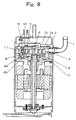
- FIG. 8 is a sectional view of the scroll compressor.
- a fixed scroll part 2 and a turning scroll part 4 form a compression chamber 5.
- a spiral lap 2a rises from a mirror plate 2b.
- a spiral lap 4a rises from a mirror plate 4b.
- the compression chamber 5 is formed between the mirror plate 2b and the mirror plate 4b by meshing the spiral lap 2a and the spiral lap 4a with each other.
- a rotation-restraining mechanism restrains the turning scroll part 4 from rotating, and the turning scroll part 4 turns along a circular orbit.
- the compression chamber 5 moves while changing its volume by the turning motion of the turning scroll part 4.
- a predetermined back pressure is applied to an outer peripheral portion of the turning scroll part 4 and a back surface of the spiral lap so that the turning scroll part 4 is not separated from the fixed scroll part 2 and is not overthrown.
- Refrigerant gas sucked by the intake pipe 1 passes through an intake chamber 3 of the fixed scroll part 2 and is trapped in a compression chamber 5 formed by meshing the fixed scroll part 2 and the turning scroll part 4 with each other, and the refrigerant gas is compressed while reducing a volume of the compression chamber 5 toward a center of the fixed scroll part 2, and the refrigerant gas is discharged from a discharge port 6.
- a back pressure chamber 8 is formed by being surrounded by the fixed scroll part 2 and a bearing 7.
- the back pressure chamber 8 it is necessary that the back pressure chamber 8 always has a back pressure of such a degree that the turning scroll part 4 is not separated from the fixed scroll part 2, but if the back pressure is excessively great, the turning scroll part 4 is strongly pushed against the fixed scroll part 2, a scroll sliding portion is abnormally worn and the input is increased.
- a back pressure adjusting mechanism 9 for always keeping the back pressure constant.
- the back pressure adjusting mechanism 9 comprises a passage 10 having a valve 11. The passage 10 passes through the fixed scroll part 2 from the back pressure chamber 8 and is in communication with the intake chamber 3.
- a pressure in the back pressure chamber 8 becomes higher than a set pressure, the valve 11 is opened, oil in the back pressure chamber 8 is supplied to the intake chamber 3 so that a pressure in the back pressure chamber 8 is maintained at a constant intermediate pressure.
- the intermediate pressure is applied to the back surface of the turning scroll part 4 so that the turning scroll part 4 is not overthrown during the operation.
- the oil supplied the intake chamber 3 moves to the compression chamber 5 together with the turning motion of the turning scroll part 4 to prevent the refrigerant from leaking from between the compressed spaces.
- Japanese Patent Application Laid-open No.2001-115958 discloses a compressor capable of enhancing abrasion resistance by lowering the coefficent of friction of members constituting a compression mechanism part, wherein an HFC, an HC or CO 2 is used as coolant and an ester oil, an ether oil a carbonate oil an alkylbenzene oil, a naphthenic mineral oil or a paraffinic mineral oil is used as lubricating oil.
- Said compressor is provided with a coating layer being formed by coating slide surfaces of the members constituting the compression mechanism part with TiAICN, wherein said coating layer is inclined in the direction of depth so that carbon becomes dense on the outer surface side and sparse on the slide member side.
- the present invention has been accomplished in view of the conventional problems, and it is an object of the invention to provide an efficient and reliable scroll compressor having a simple and inexpensive structure when carbon dioxide is used as refrigerant.
- a first aspect of the present invention provides a scroll compressor in which a spiral lap of a fixed scroll part and a spiral lap of a turning scroll part are meshed with each other to form a compression chamber, a rotation-restraining mechanism restrains the turning scroll part from rotating to turn the turning scroll part along a circular orbit, a compression chamber formed between the spiral lap of the fixed scroll part and the spiral lap of the turning scroll part moves while changing a volume of the compression chamber, thereby compressing sucked refrigerant and discharging the refrigerant, wherein carbon dioxide is used as the refrigerant, an amount of lubricant to be supplied into the compression chamber is set to a ratio of 2% by weight or more and less than 20% by weight of an amount of the lubricant trapped in the compression chamber when a suction stroke of the refrigerant is completed.
- the lubricant supplied to the compression chamber functions as seal oil, and it is possible to reduce the leakage from tip clearance and sidewalls of the laps. Further, it is possible to minimize the increase of loss caused by sucking and heating. Since it is unnecessary to provide a tip seal, it is possible to reduce the costs without increasing the number of parts.
- a volume of the intake chamber of the fixed scroll part is 20% or more of a displacement volume of the compression chamber.
- the turning scroll part is provided therein with a throttle hole through which lubricant flows.
- the compressor further comprises a throttle hole through which lubricant flows intermittently by driving the turning scroll part.
- lubricant can be supplied to the compression chamber 5 in the proportions of 2% by weight or more and less than 20% by weight of the lubricant to the sucked refrigerant amount, and the supply amount can be adjusted with respect to the variation in refrigerant circulation amount. Therefore, it is possible to provide a more efficient scroll compressor.
- oil having polyalkylene glycol as main ingredient is used as the lubricant.
- oil having polyol ester as main ingredient is used as the lubricant.
- the sealing ability of the compression chamber is further enhanced and it is possible to provide a more efficient scroll compressor.
- a seventh aspect of the invention provides a scroll compressor in which a spiral lap of a fixed scroll part and a spiral lap of a turning scroll part are meshed with each other to form a compression chamber, a rotation-restraining mechanism restrains the turning scroll part from rotating to turn the turning scroll part along a circular orbit, a compression chamber formed between the spiral lap of the fixed scroll part and the spiral lap of the turning scroll part moves while changing a volume of the compression chamber, thereby compressing sucked refrigerant and discharging the refrigerant, wherein carbon dioxide is used as the refrigerant, oil having polyalkylene glycol as main ingredient is used as the lubricant, the turning scroll part is provided therein with a throttle hole through which the lubricant flows, lubricant is supplied to the compression chamber by the throttle hole in the proportions of 2% by weight or more and less than 20% by weight of the lubricant to the refrigerant trapped in the compression chamber when a suction stroke of the refrigerant is completed.
- the lubricant supplied to the compression chamber functions as seal oil, and it is possible to reduce the leakage from tip clearance of the laps and leakage from sidewalls. Further, it is possible to minimize the increase of loss caused by sucking and heating. Since it is unnecessary to provide a tip seal, it is possible to reduce the costs without increasing the number of parts, and it is possible to inexpensively realize the means for supplying lubricant to the compression chamber 5 in the proportions of 2% by weight or more and less than 20% by weight of the lubricant to the sucked refrigerant amount. Further, since oil having polyalkylene glycol as main ingredient is used, it is possible to enhance the machine efficiency with respect to the entire operation region and to reduce the leakage loss and thus, it is possible to provide a more efficient scroll compressor.
- An eighth aspect of the invention provides a scroll compressor in which a spiral lap of a fixed scroll part and a spiral lap of a turning scroll part are meshed with each other to form a compression chamber, a rotation-restraining mechanism restrains the turning scroll part fromrotating to turn the turning scroll part along a circular orbit, a compression chamber formed between the spiral lap of the fixed scroll part and the spiral lap of the turning scroll part moves while changing a volume of the compression chamber, thereby compressing sucked refrigerant and discharging the refrigerant, wherein carbon dioxide is used as the refrigerant, oil having polyol ester as main ingredient is used as the lubricant, the turning scroll part is provided therein with a throttle hole through which the lubricant flows, lubricant is supplied to the compression chamber by the throttle hole in the proportions of 2% by weight or more and less than 20% by weight of the lubricant to the refrigerant trapped in the compression chamber when a suction stroke of the refrigerant is completed.
- the lubricant supplied to the compression chamber functions as seal oil, and it is possible to reduce the leakage from tip clearance of the laps and leakage from sidewalls. Further, it is possible to minimize the increase of loss caused by sucking and heating. Since it is unnecessary to provide a tip seal, it is possible to reduce the costs without increasing the number of parts, and it is possible to inexpensively realize the means for supplying lubricant to the compression chamber 5 in the proportions of 2% by weight or more and less than 20% by weight of the lubricant to the sucked refrigerant amount. Further, since oil having polyol ester as main ingredient is used as the lubricant, under a condition in which the refrigerant circulation amount is large, the sealing ability of the compression chamber is further enhanced and it is possible to provide a more efficient scroll compressor.
- Fig. 1 is a sectional view of a scroll compressor according to a first embodiment.
- the scroll compressor includes a compressing mechanism and a motor mechanism in a hermetical container 20.
- the compressing mechanism is disposed at an upper portion in the hermetical container 20, and the motor mechanism is disposed below the compressing mechanism.
- An intake pipe 1 and a discharge pipe 21 are provided on an upper portion of the hermetical container 20.
- An oil reservoir 22 in which lubricant is accumulated is provided at a lower portion in the hermetical container 20.
- a compression chamber 5 comprising a plurality of compressed spaces is formed by the fixed scroll part 2 and the turning scroll part 4.
- the fixed scroll part 2 has a spiral lap 2a rising from a mirror plate 2b.
- the turning scroll part 4 has a spiral lap 4a rising from a mirror plate 4b.
- the compression chamber 5 is formed between the mirror plate 2b and the mirror plate 4b by meshing the spiral lap 2a and the spiral lap 4a with each other.
- a rotation-restraining mechanism 22 restrains the turning scroll part 4 from rotating, and the turning scroll part 4 turns along a circular orbit.
- the plurality of compressed spaces constituting the compression chamber 5 move while changing their volumes by the turning motion of the turning scroll part 4.
- a predetermined back pressure is applied to an outer peripheral portion of the turning scroll part 4 and a back surface of the spiral lap so that the turning scroll part 4 is not separated from the fixed scroll part 2 and is not overthrown.
- Refrigerant gas sucked by the intake pipe 1 passes through an intake chamber 3 of the fixed scroll part 2 and is trapped in the compression chamber 5 formed by meshing the fixed scroll part 2 and the turning scroll part 4 with each other.
- the refrigerant gas is compressed while reducing a volume of the compression chamber 5 toward a center of the fixed scroll part 2, and the refrigerant gas is discharged from a discharge port 6.
- a back pressure chamber 8 is formed by being surrounded by the fixed scroll part 2 and a bearing 7. It is necessary that the back pressure chamber 8 always has a back pressure of such a degree that the turning scroll part 4 is not separated from the fixed scroll part 2.
- a ring-like seal member 7a is provided on that upper surface of the bearing 7 which is opposed to the turning scroll part 4.
- a back pressure adjusting mechanism 9 always constantly maintains the back pressure of the turning scroll part 4.
- the back pressure adjusting mechanism 9 has a passage 10 provided with a valve 11.
- the passage 10 passes through the fixed scroll part 2 from the back pressure chamber 8 and is in communication with the intake chamber 3. If a pressure in the back pressure chamber 8 becomes higher than a set pressure, the valve 11 is opened, oil in the back pressure chamber 8 is supplied to the intake chamber 3, and a pressure in the back pressure chamber 8 is maintained at a constant intermediate pressure.
- the intermediate pressure is applied to the back surface of the turning scroll part 4 so that the turning scroll part 4 is not overthrown during operation.
- the oil supplied the intake chamber 3 moves to the compression chamber 5 together with the turning motion of the turning scroll part 4 to prevent the refrigerant from leaking from between the plurality of compressed spaces which constitute the compression chamber 5.
- Lubricant accumulated in an oil reservoir 22 passes through a passage 23 formed in a shaft 13 and is introduced into an upper end portion of the shaft 13.
- the lubricant introduced into the upper end portion of the shaft 13 lubricates slide surfaces between the shaft 13 and the turning scroll part 4, and slide surfaces between the shaft 13 and the bearing 7.
- a portion of the lubricant passes through a communication passage 24 provided in the turning scroll part 4, and is reduced in pressure in a throttle hole 12 mounted to the communication passage 24 and then, the portion of the lubricant is supplied to the back pressure chamber 8.
- the valve 11 is opened, the lubricant in the back pressure chamber 8 is supplied to the intake chamber 3, and the lubricant accumulated in the back pressure chamber 8 functions as seal oil.
- the intake pipe 1, the intake chamber 3 and the back pressure adjusting mechanism 9 are superposed on each other, they are divided and illustrated on the left and right sides with respect to the shaft 13 for convenience's sake.
- Table 1 shows discharge pressure, intake pressure, compression ratio and the number of revolution under four different operation conditions.
- Table 1 High pressure [MPa] Low pressure [MPa] Compression ratio The number of revolution [l/s] Condition 1 8.0 3.8 2.1 17 Condition 2 9.0 5.0 1.8 37 Condition 3 10.0 4.0 2.5 62 Condition 4 9.0 3.0 3.0 62
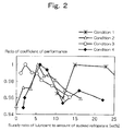
- Fig. 2 shows a supply rate of lubricant and ratio of coefficient of performance with respect to the sucked refrigerant amount under the four different operation conditions shown in Table 1.
- the sucked refrigerant amount means an amount of refrigerant which is trapped when the scroll compressor completes the suction stroke.
- the ratio of coefficient of performance is a value obtained by dividing a coefficient of performance under the various conditions by a maximum value of the coefficient of performance. As can be found from Fig. 2, if lubricant is supplied to the compression chamber 5 in the proportions of 2% by weight or more and less than 20% by weight of the lubricant to the sucked refrigerant amount, the coefficient of performance becomes maximum.
- a case in which R410A is used as lubricant and a case in which carbon dioxide is used as lubricant are compared with each other.
- the supply ratio and the ratio of coefficient of performance of the lubricant to the sucked refrigerant amount when carbon dioxide was used were measured under the condition 2.
- the supply ratio and the ratio of coefficient of performance of the lubricant to the sucked refrigerant amount when R410A was used were measured by a scroll compressor which was designed such that the freezing ability and the frequency under the condition 2 when carbon dioxide was used became substantially equal to each other. It can be found from Fig.
- Fig. 4 shows enlarged cross sections of the fixed scroll part 2, the intake chamber 3, the turning scroll part 4 and the compression chamber 5.
- the volume of the intake chamber 3 is about 14% of displacement volume of the compression chamber 5.
- the displacement volume of the compression chamber means the entire volume of a space which sucks refrigerant during one rotation of the turning scroll part.
- the volume of the intake chamber 3 is a volume of a space generated between the suction pipe and the compressed space.
- the intake chamber 3 which is larger by a value corresponding to the refrigerant viscosity at the time of suction is formed, and when the volume of the intake chamber 3 of the fixed scroll part 2 is 20% or higher than the displacement volume of the compression chamber 5, the lubricant and the refrigerant can be mixed sufficiently before the refrigerant is compressed and thus, it is possible to enhance the sealing ability of the compression chamber 5 and to further enhance the effect which reduces the leakage.
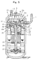
- Fig. 5 shows a second embodiment.
- the throttle hole in the embodiment shown in Fig. 1 is driven by the turning scroll part 4 to intermittently supply lubricant. That is, as shown in Fig. 5, an opening of the throttle hole 12 is provided in that lower surface of the turning scroll part 4 which is opposed to the bearing 7. If the turning scroll part 4 is driven, the opening of the throttle hole 12 straddles the seal member 7A of the bearing 7 and is positioned on the side of the inner periphery and on the side of the outer periphery of the seal member 7A. If the opening is located on the side of the outer periphery of the seal member 7A, lubricant is supplied to the back pressure chamber 8. If the opening is located on the side of the inner periphery of the seal member 7A, lubricant is not supplied to the back pressure chamber 8.
- Q represents a supply amount
- C represents a constant
- ⁇ P represents a pressure difference
- f represents frequency
- v represents kinetic viscosity
- d represents a diameter of a throttle hole
- To represents supply time per one rotation.
- Fig. 7 shows third and fourth embodiments.
- compressor performance when oil having polyalkylene glycol as main ingredient is used and when oil having polyol ester as main ingredient is used is compared.
- oil having polyalkylene glycol as main ingredient since compatibility with respect to carbon dioxide is low, if refrigerant and lubricant are not mixed sufficiently before the compression is started, the sealing ability is deteriorated.
- the polyalkylene glycol can excellently maintain the lubricity of the sliding portion.
- the lubricant supplied to the compression chamber functions as seal oil, and it is possible to reduce the leakage from tip clearance of the laps and leakage from sidewalls. Further, it is possible to minimize the increase of loss caused by sucking and heating.
- a volume of the intake chamber of the fixed scroll part is 20% or more of a displacement volume of the compression chamber, it is possible to sufficiently mix the lubricant and the refrigerant before the refrigerant is compressed, and it is possible to further enhance the sealing ability of the compression chamber and to reduce the leakage.
- the turning scroll part is provided therein with a throttle hole through which lubricant flows, it is possible to inexpensively realize the means for supplying lubricant to the compression chamber in the proportions of 2% by weight or more and less than 20% by weight of the lubricant to the sucked refrigerant amount.
- the compression chamber further comprises a throttle hole through which lubricant flows intermittently by driving the turning scroll part
- lubricant can be supplied to the compression chamber in the proportions of 2% by weight or more and less than 20% by weight of the lubricant to the sucked refrigerant amount, and the supply amount can be adjusted with respect to the variation in refrigerant circulation amount. Therefore, it is possible to provide a more efficient scroll compressor.
- oil having polyalkylene glycol as main ingredient is used as the lubricant, it is possible to enhance the machine efficiency with respect to the entire operation region and to reduce the leakage loss and thus, it is possible to provide a more efficient scroll compressor.
- oil having polyol ester as main ingredient is used as the lubricant, under a condition in which the refrigerant circulation amount is large, the sealing ability of the compression chamber is further enhanced and it is possible to provide a more efficient scroll compressor.
Landscapes
- Engineering & Computer Science (AREA)
- Mechanical Engineering (AREA)
- General Engineering & Computer Science (AREA)
- Rotary Pumps (AREA)
- Applications Or Details Of Rotary Compressors (AREA)
- Carbon And Carbon Compounds (AREA)
- Structures Of Non-Positive Displacement Pumps (AREA)
- Lubricants (AREA)
Applications Claiming Priority (2)
| Application Number | Priority Date | Filing Date | Title |
|---|---|---|---|
| JP2002150326 | 2002-05-24 | ||
| JP2002150326 | 2002-05-24 |
Publications (2)
| Publication Number | Publication Date |
|---|---|
| EP1365152A1 EP1365152A1 (en) | 2003-11-26 |
| EP1365152B1 true EP1365152B1 (en) | 2007-02-07 |
Family
ID=29397958
Family Applications (1)
| Application Number | Title | Priority Date | Filing Date |
|---|---|---|---|
| EP03011563A Expired - Lifetime EP1365152B1 (en) | 2002-05-24 | 2003-05-21 | Scroll compressor using carbon dioxide |
Country Status (7)
| Country | Link |
|---|---|
| US (1) | US6827563B2 (da) |
| EP (1) | EP1365152B1 (da) |
| KR (1) | KR100924895B1 (da) |
| CN (1) | CN100370142C (da) |
| AT (1) | ATE353403T1 (da) |
| DE (1) | DE60311605T2 (da) |
| DK (1) | DK1365152T3 (da) |
Families Citing this family (24)
| Publication number | Priority date | Publication date | Assignee | Title |
|---|---|---|---|---|
| JP3731069B2 (ja) * | 2002-07-29 | 2006-01-05 | ダイキン工業株式会社 | 圧縮機 |
| US20050207926A1 (en) * | 2002-09-24 | 2005-09-22 | Matsushita Electric Industrial Co., Ltd. | Scroll compressor |
| JP2004183632A (ja) * | 2002-12-06 | 2004-07-02 | Matsushita Electric Ind Co Ltd | 圧縮機構部の供給液回収方法と装置 |
| JP4376554B2 (ja) * | 2003-06-12 | 2009-12-02 | パナソニック株式会社 | スクロール圧縮機 |
| JP4329528B2 (ja) * | 2003-12-19 | 2009-09-09 | 株式会社豊田自動織機 | スクロールコンプレッサ |
| JP4067497B2 (ja) * | 2004-01-15 | 2008-03-26 | 株式会社デンソー | スクロール型圧縮機 |
| EP1792084B1 (en) | 2004-07-13 | 2016-03-30 | Tiax Llc | System and method of refrigeration |
| US7699589B2 (en) | 2004-11-04 | 2010-04-20 | Sanden Corporation | Scroll type fluid machine having a circulation path and inlet path for guiding refrigerant from a discharge chamber to a drive casing and to a rear-side of movable scroll |
| JP4192158B2 (ja) * | 2005-03-24 | 2008-12-03 | 日立アプライアンス株式会社 | 密閉形スクロール圧縮機及び冷凍空調装置 |
| JP2006307753A (ja) * | 2005-04-28 | 2006-11-09 | Matsushita Electric Ind Co Ltd | スクロール膨張機 |
| WO2009055009A2 (en) | 2007-10-24 | 2009-04-30 | Emerson Climate Technologies, Inc. | Scroll compressor for carbon dioxide refrigerant |
| TWI353418B (en) * | 2007-12-25 | 2011-12-01 | Ind Tech Res Inst | Scroll compressor |
| CN101498301B (zh) * | 2008-01-30 | 2010-12-01 | 财团法人工业技术研究院 | 涡卷式压缩机 |
| JP5261227B2 (ja) * | 2009-02-20 | 2013-08-14 | 三洋電機株式会社 | スクロール型圧縮機 |
| JP2010190167A (ja) * | 2009-02-20 | 2010-09-02 | Sanyo Electric Co Ltd | スクロール型圧縮機 |
| CN102812251B (zh) | 2011-03-18 | 2015-06-10 | 松下电器产业株式会社 | 压缩机 |
| JP5255157B2 (ja) * | 2011-03-18 | 2013-08-07 | パナソニック株式会社 | 圧縮機 |
| WO2013069288A1 (ja) * | 2011-11-10 | 2013-05-16 | パナソニック株式会社 | 圧縮機 |
| WO2013172002A1 (ja) * | 2012-05-14 | 2013-11-21 | パナソニック株式会社 | 圧縮機 |
| US10125767B2 (en) | 2013-05-21 | 2018-11-13 | Lg Electronics Inc. | Scroll compressor with bypass portions |
| KR102241201B1 (ko) * | 2014-08-13 | 2021-04-16 | 엘지전자 주식회사 | 스크롤 압축기 |
| CN109185131A (zh) * | 2018-10-29 | 2019-01-11 | 珠海凌达压缩机有限公司 | 涡旋压缩机、空调及车辆 |
| CN109555665B (zh) * | 2018-12-06 | 2020-04-10 | 石家庄国祥运输设备有限公司 | 轨道车辆空调机组 |
| JP7253526B2 (ja) * | 2020-12-24 | 2023-04-06 | 楽天グループ株式会社 | 情報通信システム、及び情報通信方法 |
Family Cites Families (12)
| Publication number | Priority date | Publication date | Assignee | Title |
|---|---|---|---|---|
| JPS6275091A (ja) * | 1985-09-30 | 1987-04-06 | Toshiba Corp | スクロ−ルコンプレツサ |
| JP2600400B2 (ja) * | 1989-11-02 | 1997-04-16 | 松下電器産業株式会社 | スクロール圧縮機 |
| JPH041485A (ja) | 1990-04-17 | 1992-01-06 | Sanden Corp | スクロール型圧縮機 |
| JP2956509B2 (ja) * | 1995-01-17 | 1999-10-04 | 松下電器産業株式会社 | スクロール気体圧縮機 |
| US6017205A (en) * | 1996-08-02 | 2000-01-25 | Copeland Corporation | Scroll compressor |
| US5931650A (en) * | 1997-06-04 | 1999-08-03 | Matsushita Electric Industrial Co., Ltd. | Hermetic electric scroll compressor having a lubricating passage in the orbiting scroll |
| JPH1122665A (ja) * | 1997-06-30 | 1999-01-26 | Matsushita Electric Ind Co Ltd | 密閉型電動スクロール圧縮機 |
| JP3627467B2 (ja) | 1997-09-11 | 2005-03-09 | 株式会社日立製作所 | 冷媒圧縮機および冷凍装置 |
| US6074186A (en) * | 1997-10-27 | 2000-06-13 | Carrier Corporation | Lubrication systems for scroll compressors |
| JP3851971B2 (ja) * | 1998-02-24 | 2006-11-29 | 株式会社デンソー | Co2用圧縮機 |
| JP2000283070A (ja) | 1999-03-30 | 2000-10-10 | Sanyo Electric Co Ltd | スクロール圧縮機 |
| JP3504544B2 (ja) * | 1999-10-19 | 2004-03-08 | 松下電器産業株式会社 | 圧縮機 |
-
2003
- 2003-05-20 KR KR1020030031781A patent/KR100924895B1/ko not_active Expired - Fee Related
- 2003-05-21 AT AT03011563T patent/ATE353403T1/de not_active IP Right Cessation
- 2003-05-21 EP EP03011563A patent/EP1365152B1/en not_active Expired - Lifetime
- 2003-05-21 DE DE60311605T patent/DE60311605T2/de not_active Expired - Lifetime
- 2003-05-21 DK DK03011563T patent/DK1365152T3/da active
- 2003-05-22 US US10/442,982 patent/US6827563B2/en not_active Expired - Lifetime
- 2003-05-23 CN CNB031364713A patent/CN100370142C/zh not_active Expired - Fee Related
Also Published As
| Publication number | Publication date |
|---|---|
| KR20030091681A (ko) | 2003-12-03 |
| CN1459572A (zh) | 2003-12-03 |
| DE60311605D1 (de) | 2007-03-22 |
| CN100370142C (zh) | 2008-02-20 |
| KR100924895B1 (ko) | 2009-11-02 |
| DE60311605T2 (de) | 2007-06-06 |
| EP1365152A1 (en) | 2003-11-26 |
| ATE353403T1 (de) | 2007-02-15 |
| US6827563B2 (en) | 2004-12-07 |
| DK1365152T3 (da) | 2007-05-21 |
| US20030219351A1 (en) | 2003-11-27 |
Similar Documents
| Publication | Publication Date | Title |
|---|---|---|
| US6827563B2 (en) | Scroll compressor for carbon dioxide supplied with a lubricant | |
| US8215933B2 (en) | Scroll compressor and refrigerating machine having the same | |
| KR100504931B1 (ko) | 스크롤형 압축기 | |
| US7229261B2 (en) | Scroll compressor having an annular recess located outside an annular seal portion and another recess communicating with suction port of fixed scroll | |
| AU2003227511B2 (en) | Rotary compressor | |
| US6494696B2 (en) | Scroll compressor | |
| US7699591B2 (en) | Scroll compressor with surface processed orbiting scroll plate back surface | |
| CN1163991A (zh) | 涡旋压缩机 | |
| US7581937B2 (en) | Rotary type compressor having an intermediate pressure on a surface side of its compression member | |
| JP2004225644A (ja) | スクロール圧縮機 | |
| US7458789B2 (en) | Scroll compressor | |
| KR102452563B1 (ko) | 압축기 | |
| EP1643127A2 (en) | Compressor | |
| JP4188142B2 (ja) | スクロール圧縮機 | |
| KR102407092B1 (ko) | 차량용 전동압축기 | |
| KR101510699B1 (ko) | 스크롤 압축기 및 이를 적용한 냉동기기 | |
| EP1643128A2 (en) | Compressor | |
| CN220791497U (zh) | 涡旋压缩机以及制冷设备 | |
| JPH08319959A (ja) | スクロール圧縮機 | |
| CN121047799B (zh) | 一种改性尼龙涡旋空调压缩机 | |
| JP2009052463A (ja) | スクロール圧縮機 | |
| KR101563726B1 (ko) | 개방형 압축기 | |
| KR101009701B1 (ko) | 스크롤 압축기 | |
| JP2006214335A (ja) | スクロール圧縮機 | |
| JP2007032294A (ja) | スクロール圧縮機 |
Legal Events
| Date | Code | Title | Description |
|---|---|---|---|
| PUAI | Public reference made under article 153(3) epc to a published international application that has entered the european phase |
Free format text: ORIGINAL CODE: 0009012 |
|
| AK | Designated contracting states |
Kind code of ref document: A1 Designated state(s): AT BE BG CH CY CZ DE DK EE ES FI FR GB GR HU IE IT LI LU MC NL PT RO SE SI SK TR |
|
| AX | Request for extension of the european patent |
Extension state: AL LT LV MK |
|
| 17P | Request for examination filed |
Effective date: 20031223 |
|
| 17Q | First examination report despatched |
Effective date: 20040305 |
|
| AKX | Designation fees paid |
Designated state(s): AT BE BG CH CY CZ DE DK EE ES FI FR GB GR HU IE IT LI LU MC NL PT RO SE SI SK TR |
|
| GRAP | Despatch of communication of intention to grant a patent |
Free format text: ORIGINAL CODE: EPIDOSNIGR1 |
|
| GRAS | Grant fee paid |
Free format text: ORIGINAL CODE: EPIDOSNIGR3 |
|
| GRAA | (expected) grant |
Free format text: ORIGINAL CODE: 0009210 |
|
| AK | Designated contracting states |
Kind code of ref document: B1 Designated state(s): AT BE BG CH CY CZ DE DK EE ES FI FR GB GR HU IE IT LI LU MC NL PT RO SE SI SK TR |
|
| PG25 | Lapsed in a contracting state [announced via postgrant information from national office to epo] |
Ref country code: NL Free format text: LAPSE BECAUSE OF FAILURE TO SUBMIT A TRANSLATION OF THE DESCRIPTION OR TO PAY THE FEE WITHIN THE PRESCRIBED TIME-LIMIT Effective date: 20070207 Ref country code: AT Free format text: LAPSE BECAUSE OF FAILURE TO SUBMIT A TRANSLATION OF THE DESCRIPTION OR TO PAY THE FEE WITHIN THE PRESCRIBED TIME-LIMIT Effective date: 20070207 Ref country code: CH Free format text: LAPSE BECAUSE OF FAILURE TO SUBMIT A TRANSLATION OF THE DESCRIPTION OR TO PAY THE FEE WITHIN THE PRESCRIBED TIME-LIMIT Effective date: 20070207 Ref country code: SI Free format text: LAPSE BECAUSE OF FAILURE TO SUBMIT A TRANSLATION OF THE DESCRIPTION OR TO PAY THE FEE WITHIN THE PRESCRIBED TIME-LIMIT Effective date: 20070207 Ref country code: LI Free format text: LAPSE BECAUSE OF FAILURE TO SUBMIT A TRANSLATION OF THE DESCRIPTION OR TO PAY THE FEE WITHIN THE PRESCRIBED TIME-LIMIT Effective date: 20070207 Ref country code: FI Free format text: LAPSE BECAUSE OF FAILURE TO SUBMIT A TRANSLATION OF THE DESCRIPTION OR TO PAY THE FEE WITHIN THE PRESCRIBED TIME-LIMIT Effective date: 20070207 |
|
| REG | Reference to a national code |
Ref country code: GB Ref legal event code: FG4D |
|
| REG | Reference to a national code |
Ref country code: CH Ref legal event code: EP |
|
| REG | Reference to a national code |
Ref country code: IE Ref legal event code: FG4D |
|
| REF | Corresponds to: |
Ref document number: 60311605 Country of ref document: DE Date of ref document: 20070322 Kind code of ref document: P |
|
| PG25 | Lapsed in a contracting state [announced via postgrant information from national office to epo] |
Ref country code: BG Free format text: LAPSE BECAUSE OF EXPIRATION OF PROTECTION Effective date: 20070508 |
|
| REG | Reference to a national code |
Ref country code: SE Ref legal event code: TRGR |
|
| PG25 | Lapsed in a contracting state [announced via postgrant information from national office to epo] |
Ref country code: ES Free format text: LAPSE BECAUSE OF FAILURE TO SUBMIT A TRANSLATION OF THE DESCRIPTION OR TO PAY THE FEE WITHIN THE PRESCRIBED TIME-LIMIT Effective date: 20070518 |
|
| REG | Reference to a national code |
Ref country code: DK Ref legal event code: T3 |
|
| PG25 | Lapsed in a contracting state [announced via postgrant information from national office to epo] |
Ref country code: PT Free format text: LAPSE BECAUSE OF FAILURE TO SUBMIT A TRANSLATION OF THE DESCRIPTION OR TO PAY THE FEE WITHIN THE PRESCRIBED TIME-LIMIT Effective date: 20070709 |
|
| ET | Fr: translation filed | ||
| NLV1 | Nl: lapsed or annulled due to failure to fulfill the requirements of art. 29p and 29m of the patents act | ||
| REG | Reference to a national code |
Ref country code: CH Ref legal event code: PL |
|
| PG25 | Lapsed in a contracting state [announced via postgrant information from national office to epo] |
Ref country code: SK Free format text: LAPSE BECAUSE OF FAILURE TO SUBMIT A TRANSLATION OF THE DESCRIPTION OR TO PAY THE FEE WITHIN THE PRESCRIBED TIME-LIMIT Effective date: 20070207 |
|
| PLBE | No opposition filed within time limit |
Free format text: ORIGINAL CODE: 0009261 |
|
| STAA | Information on the status of an ep patent application or granted ep patent |
Free format text: STATUS: NO OPPOSITION FILED WITHIN TIME LIMIT |
|
| PG25 | Lapsed in a contracting state [announced via postgrant information from national office to epo] |
Ref country code: RO Free format text: LAPSE BECAUSE OF FAILURE TO SUBMIT A TRANSLATION OF THE DESCRIPTION OR TO PAY THE FEE WITHIN THE PRESCRIBED TIME-LIMIT Effective date: 20070207 Ref country code: CZ Free format text: LAPSE BECAUSE OF FAILURE TO SUBMIT A TRANSLATION OF THE DESCRIPTION OR TO PAY THE FEE WITHIN THE PRESCRIBED TIME-LIMIT Effective date: 20070207 |
|
| 26N | No opposition filed |
Effective date: 20071108 |
|
| PG25 | Lapsed in a contracting state [announced via postgrant information from national office to epo] |
Ref country code: MC Free format text: LAPSE BECAUSE OF NON-PAYMENT OF DUE FEES Effective date: 20070531 |
|
| PG25 | Lapsed in a contracting state [announced via postgrant information from national office to epo] |
Ref country code: GR Free format text: LAPSE BECAUSE OF FAILURE TO SUBMIT A TRANSLATION OF THE DESCRIPTION OR TO PAY THE FEE WITHIN THE PRESCRIBED TIME-LIMIT Effective date: 20070508 |
|
| PG25 | Lapsed in a contracting state [announced via postgrant information from national office to epo] |
Ref country code: IE Free format text: LAPSE BECAUSE OF NON-PAYMENT OF DUE FEES Effective date: 20070521 |
|
| PG25 | Lapsed in a contracting state [announced via postgrant information from national office to epo] |
Ref country code: EE Free format text: LAPSE BECAUSE OF FAILURE TO SUBMIT A TRANSLATION OF THE DESCRIPTION OR TO PAY THE FEE WITHIN THE PRESCRIBED TIME-LIMIT Effective date: 20070207 |
|
| PG25 | Lapsed in a contracting state [announced via postgrant information from national office to epo] |
Ref country code: CY Free format text: LAPSE BECAUSE OF FAILURE TO SUBMIT A TRANSLATION OF THE DESCRIPTION OR TO PAY THE FEE WITHIN THE PRESCRIBED TIME-LIMIT Effective date: 20070207 |
|
| PG25 | Lapsed in a contracting state [announced via postgrant information from national office to epo] |
Ref country code: LU Free format text: LAPSE BECAUSE OF NON-PAYMENT OF DUE FEES Effective date: 20070521 |
|
| PG25 | Lapsed in a contracting state [announced via postgrant information from national office to epo] |
Ref country code: TR Free format text: LAPSE BECAUSE OF FAILURE TO SUBMIT A TRANSLATION OF THE DESCRIPTION OR TO PAY THE FEE WITHIN THE PRESCRIBED TIME-LIMIT Effective date: 20070207 Ref country code: HU Free format text: LAPSE BECAUSE OF FAILURE TO SUBMIT A TRANSLATION OF THE DESCRIPTION OR TO PAY THE FEE WITHIN THE PRESCRIBED TIME-LIMIT Effective date: 20070808 |
|
| REG | Reference to a national code |
Ref country code: FR Ref legal event code: PLFP Year of fee payment: 13 |
|
| PGFP | Annual fee paid to national office [announced via postgrant information from national office to epo] |
Ref country code: DK Payment date: 20150512 Year of fee payment: 13 Ref country code: SE Payment date: 20150512 Year of fee payment: 13 |
|
| PGFP | Annual fee paid to national office [announced via postgrant information from national office to epo] |
Ref country code: IT Payment date: 20150515 Year of fee payment: 13 Ref country code: BE Payment date: 20150514 Year of fee payment: 13 |
|
| REG | Reference to a national code |
Ref country code: FR Ref legal event code: PLFP Year of fee payment: 14 |
|
| PG25 | Lapsed in a contracting state [announced via postgrant information from national office to epo] |
Ref country code: BE Free format text: LAPSE BECAUSE OF NON-PAYMENT OF DUE FEES Effective date: 20160531 |
|
| REG | Reference to a national code |
Ref country code: DK Ref legal event code: EBP Effective date: 20160531 |
|
| PG25 | Lapsed in a contracting state [announced via postgrant information from national office to epo] |
Ref country code: IT Free format text: LAPSE BECAUSE OF NON-PAYMENT OF DUE FEES Effective date: 20160521 Ref country code: SE Free format text: LAPSE BECAUSE OF NON-PAYMENT OF DUE FEES Effective date: 20160522 |
|
| REG | Reference to a national code |
Ref country code: FR Ref legal event code: PLFP Year of fee payment: 15 |
|
| PG25 | Lapsed in a contracting state [announced via postgrant information from national office to epo] |
Ref country code: DK Free format text: LAPSE BECAUSE OF NON-PAYMENT OF DUE FEES Effective date: 20160531 |
|
| REG | Reference to a national code |
Ref country code: FR Ref legal event code: PLFP Year of fee payment: 16 |
|
| PGFP | Annual fee paid to national office [announced via postgrant information from national office to epo] |
Ref country code: GB Payment date: 20180329 Year of fee payment: 16 |
|
| PGFP | Annual fee paid to national office [announced via postgrant information from national office to epo] |
Ref country code: DE Payment date: 20180508 Year of fee payment: 16 |
|
| PGFP | Annual fee paid to national office [announced via postgrant information from national office to epo] |
Ref country code: FR Payment date: 20180412 Year of fee payment: 16 |
|
| REG | Reference to a national code |
Ref country code: DE Ref legal event code: R119 Ref document number: 60311605 Country of ref document: DE |
|
| GBPC | Gb: european patent ceased through non-payment of renewal fee |
Effective date: 20190521 |
|
| PG25 | Lapsed in a contracting state [announced via postgrant information from national office to epo] |
Ref country code: DE Free format text: LAPSE BECAUSE OF NON-PAYMENT OF DUE FEES Effective date: 20191203 Ref country code: GB Free format text: LAPSE BECAUSE OF NON-PAYMENT OF DUE FEES Effective date: 20190521 |
|
| PG25 | Lapsed in a contracting state [announced via postgrant information from national office to epo] |
Ref country code: FR Free format text: LAPSE BECAUSE OF NON-PAYMENT OF DUE FEES Effective date: 20190531 |