EP1365402A2 - Vorrichtung und Verfahren zur Aktualisierung von Filterabgreifkoeffizienten eines Entzerrers - Google Patents
Vorrichtung und Verfahren zur Aktualisierung von Filterabgreifkoeffizienten eines Entzerrers Download PDFInfo
- Publication number
- EP1365402A2 EP1365402A2 EP03252017A EP03252017A EP1365402A2 EP 1365402 A2 EP1365402 A2 EP 1365402A2 EP 03252017 A EP03252017 A EP 03252017A EP 03252017 A EP03252017 A EP 03252017A EP 1365402 A2 EP1365402 A2 EP 1365402A2
- Authority
- EP
- European Patent Office
- Prior art keywords
- filter tap
- tap coefficients
- filter
- unit
- coefficient
- Prior art date
- Legal status (The legal status is an assumption and is not a legal conclusion. Google has not performed a legal analysis and makes no representation as to the accuracy of the status listed.)
- Withdrawn
Links
Images





Classifications
-
- G—PHYSICS
- G11—INFORMATION STORAGE
- G11B—INFORMATION STORAGE BASED ON RELATIVE MOVEMENT BETWEEN RECORD CARRIER AND TRANSDUCER
- G11B20/00—Signal processing not specific to the method of recording or reproducing; Circuits therefor
- G11B20/10—Digital recording or reproducing
-
- G—PHYSICS
- G11—INFORMATION STORAGE
- G11B—INFORMATION STORAGE BASED ON RELATIVE MOVEMENT BETWEEN RECORD CARRIER AND TRANSDUCER
- G11B20/00—Signal processing not specific to the method of recording or reproducing; Circuits therefor
- G11B20/10—Digital recording or reproducing
- G11B20/10009—Improvement or modification of read or write signals
-
- G—PHYSICS
- G11—INFORMATION STORAGE
- G11B—INFORMATION STORAGE BASED ON RELATIVE MOVEMENT BETWEEN RECORD CARRIER AND TRANSDUCER
- G11B20/00—Signal processing not specific to the method of recording or reproducing; Circuits therefor
- G11B20/10—Digital recording or reproducing
- G11B20/18—Error detection or correction; Testing, e.g. of drop-outs
Definitions
- the present invention relates to updating of the filter tap coefficients of an equalizer, and more particularly, to an apparatus and method for updating the filter tap coefficients of an equalizer, by which the filter tap coefficients of the equalizer can be normally updated without errors even when a defect is generated on an optical disc or track jumping occurs in an optical disc recording/reproducing apparatus.
- a partial response maximum likelihood (PRML) reading technique adopting a Viterbi decoding technique is used.
- An equalizer having a finite impulse response (FIR) filter unit composed of a plurality of digital filters is installed at the front portion of a Viterbi decoder, and equalizes the waveforms of a radio frequency (RF) signal reflected by an optical disc so that the RF signal has a level required by the Viterbi decoder.
- FIR finite impulse response
- the RF signal becomes unstable. Accordingly, an error is generated in updating the filter tap coefficients of an equalizer, so that the filter tap coefficients are diffused to unstable area values. Therefore, the equalizer becomes unstable, and thus freezing or breaking of image screens occurs.
- the present invention provides an apparatus for updating the filter tap coefficients of an equalizer, by which the filter tap coefficients of the equalizer can be normally updated without errors even when a defect exists on an optical disc or track jumping occurs.
- the present invention also provides a method of updating the filter tap coefficients of an equalizer, by which the filter tap coefficients of the equalizer can be normally updated without errors even when a defect exists on an optical disc or track jumping occurs.
- an apparatus for updating filter tap coefficients of an equalizer in which a filter unit filters an error signal included in an input signal, which is a radio frequency (RF) signal reflected by an optical disc.
- a defect signal detection unit detects whether the input signal is defective and outputting an update stop signal.
- a coefficient updating unit stops the updating of a plurality of filter tap coefficients of the filter unit in response to the update stop signal and outputs the current filter tap coefficients to the filter unit.
- the defect signal detection unit further receives a track jump signal, detects whether the track jump signal is defective, and outputs the update stop signal.
- the filter tap coefficient apparatus further includes a control unit outputting a predetermined reference voltage, which determines whether the input signal is defective, to the defect signal detection unit.
- an apparatus for updating filter tap coefficients of an equalizer in which a filter unit filters an error signal included in an input signal, which is an RF signal reflected by an optical disc.
- a coefficient updating unit updates a plurality of filter tap coefficients of the filter unit and outputs the updated filter tap coefficients to the filter unit.
- a control unit outputs predetermined initial filter tap coefficient values.
- An initial coefficient value storage unit receives the initial filter tap coefficient values from the control unit, stores the received initial values, and outputs the initial values to the coefficient updating unit.
- a re-initialization signal generation unit receives filter tap coefficients from the coefficient updating unit, detects whether the filter tap coefficients are diffused, generates a filter tap coefficient re-initialization signal if the filter tap coefficients are diffused, and outputs the filter tap coefficient re-initialization signal to the coefficient updating unit.
- the coefficient updating unit updates filter tap coefficients using the initial filter tap coefficient values received from the initial coefficient value storage unit, in response to the filter tap coefficient re-initialization signal.
- the re-initialization signal generation unit includes: an adder (121) receiving filter tap coefficients from the coefficient updating unit and adding the received filter tap coefficients; and a comparator comparing the output value of the adder with a predetermined reference value.
- the adder obtains a sum T1 of all of the filter tap coefficients received from the coefficient updating unit, and the comparator receives a bottom threshold TH1 and a top threshold TH2 from the control unit and outputs the re-initialization signal if the sum T1 is smaller than the bottom threshold TH1 or greater than the top threshold TH2.
- the initial coefficient value storage unit receives from the control unit the filter tap coefficients of an equalizer that are in a stable state a predetermined period of time after the initial operation of the equalizer and stores the received filter tap coefficients.
- an apparatus for updating the filter tap coefficients of an equalizer in which a filter unit filters an error signal included in an input signal, which is an RF signal reflected by an optical disc.
- a defect signal detection unit detects whether the input signal is defective and outputs an update stop signal. If the update stop signal represents that updating is to be stopped, a coefficient updating unit stops the updating of a plurality of filter tap coefficients of the filter unit and outputs the current filter tap coefficients to the filter unit. On the other hand, if the update stop signal does not represent that updating is to be stopped, the coefficient updating unit updates the filter tap coefficients and outputs the updated filter tap coefficients to the filter unit.
- a control unit outputs a predetermined reference voltage, which determines whether the input signal is defective, to the defect signal detection unit and outputs predetermined initial filter tap coefficient values.
- An initial coefficient value storage unit receives the initial filter tap coefficient values from the control unit, stores the received initial values, and outputs the initial values to the coefficient updating unit.
- a re-initialization signal generation unit receives filter tap coefficients from the coefficient updating unit, detects whether the filter tap coefficients are diffused, generates a tap coefficient re-initialization signal if the filter tap coefficients are diffused, and outputs the tap coefficient re-initialization signal to the coefficient updating unit.
- the coefficient updating unit updates filter tap coefficients using the initial filter tap coefficient values received from the initial coefficient value storage unit, in response to the tap coefficient re-initialization signal.
- the defect signal detection unit further receives a track jump signal, detects whether the track jump signal is defective, and outputs the update stop signal.
- the re-initialization signal generation unit includes: an adder receiving filter tap coefficients from the coefficient updating unit and adding the received filter tap coefficients; and a comparator comparing the output value of the adder with the predetermined reference value received from the control unit.
- the adder obtains a sum T1 of all of the filter tap coefficients received from the coefficient updating unit, and the comparator receives a bottom threshold TH1 and a top threshold TH2 from the control unit and outputs the re-initialization signal if the sum T1 is smaller than the bottom threshold TH1 or greater than the top threshold TH2.
- the initial coefficient value storage unit receives from the control unit the filter tap coefficients of an equalizer that are stabilized a predetermined period of time after the initial operation of the equalizer and stores the received filter tap coefficients.
- a method of updating the filter tap coefficients of an equalizer in which an input signal, which is an RF signal reflected by an optical disc is first received. Then, whether the input signal is defective is detected. If a defect is detected from the input signal, the updating of a plurality of filter tap coefficients of an equalizer filter unit is stopped, and the current filter tap coefficients are output to the equalizer filter unit.
- a track jump signal is further received and undergoes the defect detection step and the filter tap coefficient updating step.
- a predetermined reference value is compared with the input signal.
- a method of updating the filter tap coefficients of an equalizer in which a plurality of filter tap coefficients are received from an equalizer filter unit. Next, a reference value for determining whether filter tap coefficient re-initialization is to be performed is obtained from the filter tap coefficients. Then, the reference value is compared with a predetermined standard value, and the filter tap coefficients are re-initialized.
- a sum T1 of all of the filter tap coefficients is determined as the reference value.
- the filter tap coefficients are re-initialized if the sum T1 is smaller than a bottom threshold TH1 or greater than a top threshold TH2.
- the filter tap coefficients of the equalizer filter unit are re-initialized using filter tap coefficients pre-stored in an equalizer stabilized a predetermined period of time after the initial operation of the equalizer.
- a method of updating the filter tap coefficients of an equalizer in which an input signal, which is an RF signal reflected by an optical disc, is first received. Next, whether the input signal is defective is detected. If a defect is detected from the input signal, the updating of a plurality of filter tap coefficients of an equalizer filter unit is stopped, and the current filter tap coefficients are output to the equalizer filter unit. On the other hand, if no defects are detected from the input signal, a reference value for determining whether filter tap coefficient re-initialization is to be performed is obtained from the filter tap coefficients. Then, the reference value is compared with a predetermined standard value, and the filter tap coefficients are re-initialized.
- a track jump signal is further received and undergoes the defect detection step and the filter tap coefficient updating step.
- a predetermined reference value is compared with the input signal.
- a sum T1 of all of the filter tap coefficients is determined as the reference value. If the sum T1 is smaller than a bottom threshold TH1 or greater than a top threshold TH2, the filter tap coefficients are re-initialized.
- the filter tap coefficients of the equalizer filter unit are re-initialized using filter tap coefficients pre-stored in an equalizer stabilized a predetermined period of time after the initial operation of the equalizer.
- a radio frequency (RF) signal is unstablized, such that an error is generated in updating the filter tap coefficients of an equalizer.
- RF radio frequency
- FIG. 1 is a block diagram of an apparatus for updating the filter tap coefficients of an equalizer, according to a first embodiment of the present invention.
- An analog-to-digital converter (ADC) 101 receives an electrical RF signal corresponding to the amount of laser light reflected by an optical disc, samples the RF signal, and converts the resultant RF signal into a digital signal.
- ADC analog-to-digital converter
- a direct current (DC) offset remover 103 removes a DC offset from the sampled RF signal.
- a phase locked loop (PLL) 105 produces a system clock signal.
- a finite impulse response (FIR) filter unit 106 composed of a plurality of digital filters receives the output signal of the ADC 101 and sets the waveform of an RF signal so that the RF signal has a level required by a Viterbi decoder.
- a defect signal detection unit 107 receives the sampled RF signal from the ADC 101 and/or a track jump signal, representing that a pick-up unit (not shown) jumped a track, from a servo unit (not shown), checks if the RF signal has a defect, and outputs an update stop signal determining whether tap coefficient updating is to be stopped.
- the RF signal becomes larger or smaller compared to a normal case.
- a defect signal indicating that the received RF signal is abnormal is generated.
- the defect signal detection unit 107 receives a sampled RF signal from the ADC 101, detects the upper and lower thresholds of the received sampled RF signal using a filter (not shown), and applies the detected upper and lower thresholds to a comparator (not shown). If the upper and lower thresholds of the received sampled RF signal are greater or smaller than their respective reference values, a defect signal is generated.
- the defect signal detection unit 107 receives the track jump signal from the servo unit (not shown) and generates a defect signal using the track jump signal.
- the defect signal detection unit 107 outputs an update stop signal for stopping tap coefficient updating, when it detects a defective RF signal corresponding to a defect or track jump section.
- a coefficient updating unit 111 receives an initialization signal from a control unit 109, reads initial values from a coefficient initial value storage unit 113, and supplies a tap coefficient to the FIR filter unit 106. Thereafter, the coefficient updating unit 111 receives data regarding tap coefficient updating from a coefficient determination unit 115 and updates filter tap coefficients.
- the coefficient updating unit 111 receives from the defect signal detection unit 107 an update stop signal that commands the coefficient updating to be stopped, it stops the coefficient updating and outputs current filter tap coefficients to the FIR filter unit 106 in order to prevent the filter tap coefficients from being diffused into unstable region values.
- the coefficient initial value storage unit 113 receives initial filter tap coefficient values from the control unit 109, stores the same, and outputs the same to the coefficient updating unit 111.
- the control unit 109 receives the filter tap coefficients of an equalizer being in a stable state a certain period of time after the initial operation from the coefficient updating unit 111 and then outputs the received filter tap coefficients to the initial coefficient value storage unit 113.
- the initial coefficient value stage unit 113 may store the filter tap coefficients received from the control unit 109 as initial values. For example, coefficient values 300ms after disc rotation are set to be initial values.
- the initial coefficient value storage unit 113 may receive initial filter tap coefficient values pre-set as default values from the control unit 109 and store them as initial values.
- a tap coefficient is C i (where i is an integer in the range of 0 to 10)
- C 4 , C 5 , and C 6 are 1 and the other filter tap coefficients are 0.
- the coefficient determination unit 115 calculates data for a tap coefficient update and provides the calculated data to the coefficient updating unit 111.
- various different conventional algorithms for determining a new coefficient There are various different conventional algorithms for determining a new coefficient.
- An example of a conventional algorithm is a least mean square (LMS) algorithm, which is disclosed in detail in Korean Publication Patent No. 2001-45325.
- LMS least mean square
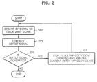
- FIG. 2 is a flowchart illustrating a tap coefficient updating method performed in the tap coefficient updating apparatus according to the first embodiment of the present invention.
- an RF signal which is an electrical signal into which laser reflected by an optical disk is converted, is applied to the ADC 101, and the defect signal detection unit 107 receives a sampled RF signal from the ADC 101 and/or a track jump signal from a servo unit (not shown), in step 201.
- the defect signal detection unit 107 checks if the RF signal has a defect, in response to the RF signal and/or the track jump signal, in step 203.
- the defect signal detection unit 107 If a defect is detected from the RF signal, the defect signal detection unit 107 outputs an update stop signal to the coefficient updating unit 111, and accordingly the coefficient updating unit 111 stops updating a plurality of filter tap coefficients and outputs the current filter tap coefficients to the FIR filter unit 106, in steps 205 and 207. Accordingly, coefficient updating is stopped when a defect is detected from the RF signal, thereby preventing filter tap coefficients from being diffused into unstable regions.
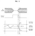
- Figure 3 is a conceptual view illustrating a defective RF signal, a detected defect signal, and a process for updating filter tap coefficients.
- the defective RF signal has a weak level during a defect period, and the defect signal detection unit 107 detects a defect signal. That is, the defect signal turns into an update stop signal and the update stop signal is applied to the coefficient updating unit 111 in order to stop updating over the defect period.
- the sum of the filter tap coefficients, ⁇ C i remains constant during the defect period from point C to point D when coefficient updating stops.
- the sum of the filter tap coefficients, ⁇ C i serves as a reference value representing whether the filter tap coefficients of an equalizer are normally updated.
- the defect period is terminated, and coefficient updating resumes.
- the RF signal is unstable and the reference value ⁇ C i may turn into a value E or F.
- the RF signal reference value ⁇ C i belongs to an unstable section.
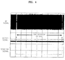
- Figure 4 shows a malfunction of a system due to diffusion of filter tap coefficients into an unstable section during the above-described transition period between points D and E or points D and F. Coefficient updating is paused during the defect period, but filter tap coefficients are diffused during the transition period, such that a sync detector outputs a low sync ok signal that indicates a malfunction of the system.
- a high sync ok signal represents the normal operation of a system.
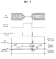
- Figure 5 is a conceptual view explaining tap coefficient re-initialization in order to solve the system malfunction problem.
- the reference value ⁇ C i is not updated to a stable section between a top threshold and a bottom threshold but to an unstable section during the transition period, tap coefficient updating stops and initialization resumes, so that the reference value ⁇ C i is located in the stable section.
- FIG. 6 is a block diagram of an apparatus for updating the filter tap coefficients of an equalizer, according to a second embodiment of the present invention. Since the tap coefficient updating apparatus according to the second embodiment is similar to the tap coefficient updating apparatus of Figure 1, only the different elements will be described without description of like elements.
- a re-initialization signal generation unit 120 receives filter tap coefficients from the control unit 109, detects whether the filter tap coefficients are diffused, generates a tap coefficient re-initialization signal if the filter tap coefficients are diffused, and outputs the tap coefficient re-initialization signal to the coefficient updating unit 111.
- the coefficient updating unit 111 updates filter tap coefficients using the initial coefficient values received from the initial coefficient value storage unit 113.
- the initial coefficient value storage unit 113 outputs the pre-stored initial coefficient values to the coefficient updating unit 111.
- the coefficient updating unit 111 reads an initial filter tap coefficient value from the initial coefficient value storage unit 113 and initializes the filter tap coefficients.
- the control unit 109 receives the filter tap coefficients of an equalizer that are in a stable state a certain period of time after the initial operation of the equalizer from the coefficient updating unit 111 and then outputs the received filter tap coefficients to the initial coefficient value storage unit 113.
- the initial coefficient value stage unit 113 may store the filter tap coefficients received from the control unit 109 as initial values. For example, coefficient values 300ms after rotation of a disc when a re-initialization signal is 0, that is, in a normal system when re-initialization is not performed, are set as initial values.
- the initial coefficient value storage unit 113 may receive initial filter tap coefficient values pre-set as default values from the control unit 109 and store them as initial values.
- a filter tap coefficient is C i (where i is an integer in the range of 0 to 10)
- C 4 , C 5 , and C 6 are 1 and the other filter tap coefficients are 0.
- the control unit 109 provides predetermined reference values to the re-initialization signal generation unit 120 and outputs a control signal so that the re-initialization signal generation unit 120 performs a predetermined operation.
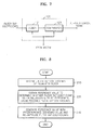
- Figure 7 shows the re-initialization signal generation unit 120 including an adder 121 and a comparator 123.
- the adder 121 sums the filter tap coefficients received from the coefficient updating unit 111 to obtain and output a value T1 to the comparator 123.
- the adder 121 adds filter tap coefficients excluding a predetermined filter tap coefficient C k , among the filter tap coefficients received from the coefficient updating unit 111, to obtain a value T2.
- the adder 121 receives a bottom threshold TH3 and a top threshold TH4 from the control unit 109, adds the value T2 to the bottom threshold TH3 to obtain a value T3, and adds the value T2 to the top threshold TH4 to obtain a value T4.
- the adder 121 outputs the predetermined filter tap coefficient C k and the values T3 and T4 to the comparator 123.
- the predetermined filter tap coefficient C k is the tap coefficient of a filter located at the center, among a plurality of filters included in the FIR filter unit 106.
- the comparator 123 In response to the value T1 from the adder 121 and a control signal from the control unit 109, the comparator 123 receives a bottom threshold TH1 and a top threshold TH2 from the control unit 109. If the value T1 is greater than TH2 and smaller than TH1, in response to a control signal from the control unit 109, the comparator 123 outputs a re-initialization signal for re-initializing the filter tap coefficients of the coefficient updating unit 111 to the coefficient updating unit 111.
- the comparator 123 receives a bottom threshold TH1 and a top threshold TH2 from the control unit 109. If the value T1 is greater than TH2 and smaller than TH1, in response to a control signal from the control unit 109, the comparator 123 outputs a re-initialization signal for re-initializing the filter tap coefficients of the coefficient updating unit 111 to the coefficient updating unit 111.
- Figure 8 is a flowchart illustrating a filter tap coefficient updating method performed in the filter tap coefficient updating apparatus according to the second embodiment of the present invention.
- the re-initialization signal generation unit 120 receives a plurality of filter tap coefficients of an equalizer filter from the coefficient updating unit 111, in step 210.
- the adder 121 of the re-initialization signal generation unit 120 obtains a reference value to determine whether filter tap coefficients are to be re-initialized, using the received filter tap coefficients, in step 220.
- the reference value is either the value T1, which is the sum of all of the received filter tap coefficients, or the value T2, which is the sum of the received filter tap coefficients excluding the predetermined filter tap coefficient C k .
- the comparator 123 of the re-initialization signal generation unit 120 compares the reference value received from the adder 121 with a predetermined standard value and outputs a re-initialization signal to the coefficient updating unit 111 so that the coefficient updating unit 111 re-initializes the filter tap coefficients, in step 203.
- the predetermined standard value can be a top threshold or a bottom threshold.
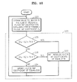
- FIGs 9 and 10 are flowcharts illustrating steps 220 and 230 of Figure 8 in greater detail.
- step 221 corresponds to a case when the value T1 is used as the reference value in step 220 of Figure 8.
- Step 230 of Figure 8 includes steps 231 through 234.
- the adder 121 adds received filter tap coefficients to obtain the value T1 as a reference value, in step 221.
- the comparator 213 determines whether the reference value T1 received from the adder 121 is smaller than the bottom threshold TH1, in step 231.
- the tap coefficient sum T1 experimentally determines a minimum value and a maximum value when an equalizer is in a stable section, that is, operates normally, and the experimentally determined minimum and maximum values are determined as the bottom threshold TH1 and the top threshold TH2, respectively.
- TH1 is 0.25
- TH2 is 4.
- the coefficient updating unit 111 updates the filter tap coefficients of the equalizer, in step 234.
- the re-initialization signal generation unit 120 If it is determined in step 231 that the reference value T1 is less than the bottom threshold TH1, or if it is determined in step 232 that the reference value T1 is greater than the top threshold TH2, the re-initialization signal generation unit 120 outputs a re-initialization signal to the coefficient updating unit 111 so that the coefficient updating unit 111 re-initializes the filter tap coefficients of the equalizer, in step 233.
- the initial filter tap coefficient values can be pre-stored filter tap coefficients of an equalizer that are in a stable state a predetermined period of time after the initial operation of the equalizer.
- the pre-stored filter tap coefficients can be used to re-initialize filter tap coefficients.
- initial filter tap coefficient values pre-set in the control unit 109 can be used to re-initialize the filter tap coefficients.
- step 223 corresponds to a case when the value T2 is used as the reference value in step 220 of Figure 8.
- the step 230 of Figure 8 includes steps 233 through 236.
- step 223 the adder 121 adds filter tap coefficients excluding the predetermined filter tap coefficient C k , among the received filter tap coefficients, to obtain the value T2 as a reference value.
- the comparator 123 determines whether a value (C k - T2) is less than the bottom threshold TH3, in step 235.
- step 2366 if the value (C k - T2) is greater than or equal to the bottom threshold TH3, another determination is made as to whether the value (C k - T2) is greater than the top threshold TH4.
- the bottom threshold TH3 and the top threshold TH4 can be experimentally determined in the same way as the bottom threshold TH1 and the top threshold TH2.
- step 234 if the value (C k - T2) is less than or equal to the top threshold TH4, the coefficient updating unit 111 normally updates the filter tap coefficients of the equalizer.
- the re-initialization signal generation unit 120 If it is determined in step 235 that the value (C k - T2) is less than the bottom threshold TH3, or if it is determined in step 236 that the value (C k - T2) is greater than the top threshold TH4, the re-initialization signal generation unit 120 outputs a re-initialization signal to the coefficient updating unit 111 so that the coefficient updating unit 111 re-initializes the filter tap coefficients of the equalizer, in step 233.
- the initial filter tap coefficient values can be pre-stored filter tap coefficients of an equalizer that are in a stable state a predetermined period of time after the initial operation of the equalizer.
- the pre-stored filter tap coefficients can be used to re-initialize the filter tap coefficients.
- initial filter tap coefficient values pre-set in the control unit 109 can be used to re-initialize filter tap coefficients.
- An apparatus and method of updating the filter tap coefficients of an equalizer can be achieved by combining the first and second embodiments. That is, in the combined embodiment, a defect signal corresponding to defect generation or track jumping is detected to determine whether filter tap coefficient updating is to be stopped. If it is determined that filter tap coefficient updating is to be stopped, the filter tap coefficient updating is stopped. If it is determined that filter tap coefficient updating is not to be stopped, another determination is made as to whether filter tap coefficients are diffused into an unstable section, and the filter tap coefficients are re-initialized.
- FIG 11 is a block diagram of an apparatus for updating the filter tap coefficients of an equalizer, according to a third embodiment of the present invention. Since the third embodiment is a combination of the filter tap coefficient updating apparatuses of Figures 1 and 6, only the elements that are different will be described, not the like elements.
- the filter tap coefficient updating apparatus When an RF signal and/or a track jumping signal are received by the defect signal detection unit 107, the filter tap coefficient updating apparatus according to the third embodiment first performs the operations of the method of Figure 2. That is, the defect signal detection unit 107 detects whether the RF signal is defective, and outputs an updating stop signal to the coefficient updating unit 111.
- the coefficient updating unit 111 stops updating the multiple filter tap coefficients of the FIR filter unit and outputs the current filter tap coefficients to the FIR filter unit 106, as described above.
- the coefficient updating unit 111 updates the filter tap coefficients and outputs the results to the FIR filter unit 106.
- the coefficient updating unit 111 also outputs the updated filter tap coefficients to the re-initialization signal generation unit 120.
- the re-initialization signal generation unit 120 performs the steps of Figures 8 through 10 on the updated filter tap coefficients in order to determine whether or not the filter tap coefficients are diffused into an unstable section. If it is determined that the updated filter tap coefficients are diffused into an unstable section, the filter tap coefficients are re-initialized.
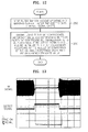
- FIG. 12 is a flowchart illustrating a filter tap coefficient updating method performed in the filter tap coefficient updating apparatus according to the third embodiment of the present invention.
- step 250 if it is determined that an RF signal and/or a track jump signal is a defect signal, filter tap coefficient updating is stopped and the current filter tap coefficients are maintained. Step 250 corresponds to steps 201 through 207 of Figure 2.
- Step 250 if a defect signal is detected, a reference value for determining whether filter tap coefficient re-initialization is to be performed is obtained from the filter tap coefficients, and the filter tap coefficients are re-initialized according to the result of a comparison of the reference value with a predetermined standard value, in step 260.
- Step 260 corresponds to steps 210 through 230 of Figure 8.
- Step 260 is also achieved by performing the steps shown in Figure 9 or 10. However, step 260 is achieved through steps 210 through 230 only if the update stop signal output from the defect signal detection unit 107 is "0", which represents that updating is to be continued.
- Figure 13 illustrates waveforms representing the operation of the filter tap coefficient updating apparatus according to the first embodiment of the present invention shown in Figure 1.
- An RF signal represents a case in which a defect exists on an optical disc.
- the defect signal detection unit 107 detects a defect period and outputs a defect signal, that is, an update stop signal.
- the coefficient updating unit 111 stops coefficient updating, maintains the current filter tap coefficients, and outputs the same to the FIR filter unit 106.
- a sync okay signal that represents whether a system is operating normally after the defect period remains at a high value, which shows that the system operates normally.
- Figure 14A shows a waveform representing the operation of the filter tap coefficient updating apparatus of Figure 11 in the case of an RF signal.
- the defect signal detection unit 107 detects a defect period and outputs a defect signal, that is, an update stop signal.
- a defect signal that is, an update stop signal.
- a re-initialization signal is produced by the re-initialization signal generation unit 120 in order to re-initialize the filter tap coefficients.
- the sync okay signal that represents whether a system is operating normally after the defect period remains at a high value, thus representing that the system is operating normally.
- Figure 14B shows a waveform representing the operation of the filter tap coefficient updating apparatus of Figure 11 when a pickup means jumps a track.
- the defect signal detection unit 107 detects a track jump period based on a track jump signal received from a servo unit and outputs an update stop signal, which is the track jump signal.
- a re-initialization signal is produced by the re-initialization signal generation unit 120 in order to re-initialize filter tap coefficients.
- the sync okay signal that represents whether a system is operating normally after the defect period keeps a high value, thus representing that the system is operating normally.
- the invention can also be embodied as computer readable codes on a computer readable recording medium.
- the computer readable recording medium is any data storage device that can store data which can be thereafter read by a computer system. Examples of the computer readable recording medium include read-only memory (ROM), random-access memory (RAM), CD-ROMs, magnetic tapes, floppy disks, optical data storage devices, and so on.
- the computer readable codes can be transmitted via a carrier wave such as Internet.
- the computer readable recording medium can also be distributed over a network coupled computer system so that the computer readable code is stored and executed in a distributed fashion.
- the filter tap coefficient updating is normally performed without errors even if a defect exists on an optical disc or track jumping occurs, so that freezing or breaking of an image screen is prevented.
Landscapes
- Engineering & Computer Science (AREA)
- Signal Processing (AREA)
- Signal Processing For Digital Recording And Reproducing (AREA)
- Filters That Use Time-Delay Elements (AREA)
- Optical Recording Or Reproduction (AREA)
Applications Claiming Priority (2)
| Application Number | Priority Date | Filing Date | Title |
|---|---|---|---|
| KR1020020028169A KR100878524B1 (ko) | 2002-05-21 | 2002-05-21 | 등화기의 필터 탭계수 갱신 장치 및 갱신 방법 |
| KR2002028169 | 2002-05-21 |
Publications (1)
| Publication Number | Publication Date |
|---|---|
| EP1365402A2 true EP1365402A2 (de) | 2003-11-26 |
Family
ID=29398537
Family Applications (1)
| Application Number | Title | Priority Date | Filing Date |
|---|---|---|---|
| EP03252017A Withdrawn EP1365402A2 (de) | 2002-05-21 | 2003-03-31 | Vorrichtung und Verfahren zur Aktualisierung von Filterabgreifkoeffizienten eines Entzerrers |
Country Status (6)
| Country | Link |
|---|---|
| US (1) | US7394735B2 (de) |
| EP (1) | EP1365402A2 (de) |
| JP (1) | JP2003338134A (de) |
| KR (1) | KR100878524B1 (de) |
| CN (2) | CN1317707C (de) |
| TW (1) | TWI246071B (de) |
Cited By (2)
| Publication number | Priority date | Publication date | Assignee | Title |
|---|---|---|---|---|
| EP2251863A3 (de) * | 2007-06-01 | 2010-12-22 | Sharp Kabushiki Kaisha | Optisches Informationsaufzeichnungsmedium und optisches Informationsverarbeitungsverfahren |
| WO2012071332A1 (en) * | 2010-11-22 | 2012-05-31 | Marvell World Trade, Ltd. | Method and apparatus for defect recovery |
Families Citing this family (14)
| Publication number | Priority date | Publication date | Assignee | Title |
|---|---|---|---|---|
| JP3529767B2 (ja) * | 2002-03-08 | 2004-05-24 | 株式会社東芝 | 情報再生装置及び情報再生方法 |
| EP1524661A1 (de) * | 2003-10-14 | 2005-04-20 | Deutsche Thomson-Brandt Gmbh | Fehlerbehandlung für Aufzeichnungsmedien |
| EP1575176A1 (de) * | 2004-03-09 | 2005-09-14 | Deutsche Thomson-Brandt Gmbh | Anordnung für adaptive Bit-Wiedergewinnung |
| CN100421164C (zh) * | 2004-03-17 | 2008-09-24 | 建兴电子科技股份有限公司 | 应用于盘片读取装置的转速控制方法 |
| KR100640591B1 (ko) * | 2004-10-23 | 2006-11-01 | 삼성전자주식회사 | 감소된 면적을 가지는 부분 탭 적응 등화기 |
| KR100614241B1 (ko) | 2005-02-07 | 2006-08-21 | 삼성전자주식회사 | 적응형 등화기의 초기값 설정 방법 및 장치 |
| US7813415B2 (en) * | 2007-06-11 | 2010-10-12 | Lsi Corporation | System for automatic bandwidth control of equalizer adaptation loops |
| US8432959B2 (en) * | 2007-10-31 | 2013-04-30 | Agere Systems Llc | Method and apparatus for equalization using one or more qualifiers |
| JP2011048869A (ja) * | 2009-08-26 | 2011-03-10 | Sony Corp | 等化フィルタ装置、タップ係数更新方法、再生装置 |
| US8422609B2 (en) * | 2009-09-30 | 2013-04-16 | Lsi Corporation | Automatic filter-reset mechanism |
| US9690751B2 (en) | 2013-09-04 | 2017-06-27 | Nec Corporation | Digital processing apparatus and digital processing method |
| JP6509467B2 (ja) * | 2017-03-01 | 2019-05-08 | 三菱電機株式会社 | デジタル信号処理装置及びオーディオ装置 |
| CN115883300B (zh) * | 2022-11-29 | 2025-11-04 | 北京凯芯微科技有限公司 | 信号的处理方法、装置和芯片 |
| CN118609611B (zh) * | 2024-05-07 | 2025-03-07 | 华中科技大学 | 一种光盘数据读取过程中的回读信号样本序列检测方法 |
Family Cites Families (27)
| Publication number | Priority date | Publication date | Assignee | Title |
|---|---|---|---|---|
| US4802152A (en) * | 1986-04-07 | 1989-01-31 | U.S. Philips Corporation | Compact disc drive apparatus having an interface for transferring data and commands to and from a host controller |
| JPH0679420B2 (ja) * | 1986-06-06 | 1994-10-05 | パイオニア株式会社 | トラツキングサ−ボ装置 |
| JPH02237307A (ja) * | 1989-03-10 | 1990-09-19 | Matsushita Electric Ind Co Ltd | 適応型波形等化器 |
| CA2020059C (en) * | 1989-06-30 | 1995-05-23 | Shigemi Maeda | Modular ceramic igniter |
| JP3018040B2 (ja) * | 1990-05-11 | 2000-03-13 | セイコー精機株式会社 | ハードディスクの検査装置 |
| JPH04113522A (ja) * | 1990-09-03 | 1992-04-15 | Matsushita Electric Ind Co Ltd | 情報記録再生装置 |
| JP2936794B2 (ja) * | 1991-05-30 | 1999-08-23 | 株式会社日立製作所 | 等化方法および情報再生装置 |
| JP3039062B2 (ja) * | 1991-10-31 | 2000-05-08 | ソニー株式会社 | 磁気再生装置 |
| EP0559104B1 (de) * | 1992-02-29 | 1998-05-20 | Sony Corporation | Vorrichtung zur Aufzeichnung auf einer optischen Platte |
| JP3250678B2 (ja) * | 1992-08-25 | 2002-01-28 | ソニー株式会社 | 係数処理方法、係数処理回路およびビデオテープレコーダ |
| JPH06162422A (ja) | 1992-11-13 | 1994-06-10 | Sony Corp | 係数処理方法 |
| JPH06231409A (ja) * | 1993-02-01 | 1994-08-19 | Hitachi Ltd | 適応波形等化方式 |
| US5777967A (en) * | 1995-04-05 | 1998-07-07 | Matsushita Electric Industrial Co., Ltd. | Optical disk device |
| JPH09245435A (ja) * | 1996-03-05 | 1997-09-19 | Sony Corp | データ再生装置 |
| US5901175A (en) * | 1996-04-08 | 1999-05-04 | Samsung Electronics Co., Ltd. | Dynamically adaptive equalizer system and method |
| DE69617677T2 (de) * | 1996-09-24 | 2002-08-08 | Hewlett-Packard Co. (N.D.Ges.D.Staates Delaware), Palo Alto | Datenverarbeitungsgerät und -verfahren |
| JP3428359B2 (ja) * | 1997-03-31 | 2003-07-22 | 日本ビクター株式会社 | 波形等化回路 |
| JP3428360B2 (ja) * | 1997-03-31 | 2003-07-22 | 日本ビクター株式会社 | 波形等化回路 |
| JP3843560B2 (ja) * | 1997-11-17 | 2006-11-08 | ソニー株式会社 | アシンメトリ補正装置及びアシンメトリ補正方法 |
| JPH11234369A (ja) | 1998-02-12 | 1999-08-27 | Shishido Hatsuki | 無線電話器の着信発光表示装置 |
| JP2000182330A (ja) * | 1998-12-16 | 2000-06-30 | Matsushita Electric Ind Co Ltd | 情報再生方法及び情報再生装置 |
| JP3611472B2 (ja) * | 1999-02-02 | 2005-01-19 | 松下電器産業株式会社 | 適応等化回路 |
| US6577568B1 (en) * | 1999-03-30 | 2003-06-10 | Matsushita Electric Industrial Co., Ltd. | Optical disk apparatus using tilt and aberration correction control system |
| KR100580166B1 (ko) | 1999-11-04 | 2006-05-15 | 삼성전자주식회사 | 등화기의 필터 계수를 조절하여 재생 성능을 높이는 장치및 방법 |
| EP1158694B1 (de) * | 2000-03-27 | 2009-01-28 | NTT DoCoMo, Inc. | Räumliche und Zeitliche Entzerrer und Entzerrungsverfahren |
| US6678230B2 (en) * | 2000-10-31 | 2004-01-13 | Matsushita Electric Industrial Co., Ltd. | Waveform equalizer for a reproduction signal obtained by reproducing marks and non-marks recorded on a recording medium |
| JP2003059186A (ja) | 2001-08-10 | 2003-02-28 | Sony Corp | 適応型等化回路および該回路を用いた再生装置 |
-
2002
- 2002-05-21 KR KR1020020028169A patent/KR100878524B1/ko not_active Expired - Fee Related
-
2003
- 2003-01-30 TW TW092102158A patent/TWI246071B/zh not_active IP Right Cessation
- 2003-03-06 JP JP2003060359A patent/JP2003338134A/ja active Pending
- 2003-03-31 EP EP03252017A patent/EP1365402A2/de not_active Withdrawn
- 2003-03-31 CN CNB031081878A patent/CN1317707C/zh not_active Expired - Fee Related
- 2003-03-31 CN CNB2006100680087A patent/CN100423093C/zh not_active Expired - Fee Related
- 2003-05-06 US US10/429,954 patent/US7394735B2/en not_active Expired - Fee Related
Cited By (9)
| Publication number | Priority date | Publication date | Assignee | Title |
|---|---|---|---|---|
| EP2251863A3 (de) * | 2007-06-01 | 2010-12-22 | Sharp Kabushiki Kaisha | Optisches Informationsaufzeichnungsmedium und optisches Informationsverarbeitungsverfahren |
| EP2249338A3 (de) * | 2007-06-01 | 2010-12-22 | Sharp Kabushiki Kaisha | Optisches Informationsaufzeichnungsmedium und optisches Informationsverarbeitungsverfahren |
| EP2251864A3 (de) * | 2007-06-01 | 2010-12-22 | Sharp Kabushiki Kaisha | Optisches Informationsaufzeichnungsmedium und optisches Informationsverarbeitungsverfahren |
| EP2251865A3 (de) * | 2007-06-01 | 2010-12-22 | Sharp Kabushiki Kaisha | Optisches Informationsaufzeichnungsmedium und optisches Informationsverarbeitungsverfahren |
| US8189444B2 (en) | 2007-06-01 | 2012-05-29 | Sharp Kabushiki Kaisha | Optical information recording medium and optical information processing apparatus |
| US8441905B2 (en) | 2007-06-01 | 2013-05-14 | Sharp Kabushiki Kaisha | Optical information recording medium and optical information processing apparatus |
| US8582412B2 (en) | 2007-06-01 | 2013-11-12 | Sharp Kabushiki Kaisha | Optical information recording medium and optical information processing apparatus |
| WO2012071332A1 (en) * | 2010-11-22 | 2012-05-31 | Marvell World Trade, Ltd. | Method and apparatus for defect recovery |
| US8930781B2 (en) | 2010-11-22 | 2015-01-06 | Marvell World Trade Ltd. | Method and apparatus for defect recovery |
Also Published As
| Publication number | Publication date |
|---|---|
| TWI246071B (en) | 2005-12-21 |
| JP2003338134A (ja) | 2003-11-28 |
| CN1831961A (zh) | 2006-09-13 |
| CN1459787A (zh) | 2003-12-03 |
| CN1317707C (zh) | 2007-05-23 |
| US7394735B2 (en) | 2008-07-01 |
| KR100878524B1 (ko) | 2009-01-13 |
| US20030227842A1 (en) | 2003-12-11 |
| KR20030090168A (ko) | 2003-11-28 |
| TW200307265A (en) | 2003-12-01 |
| CN100423093C (zh) | 2008-10-01 |
Similar Documents
| Publication | Publication Date | Title |
|---|---|---|
| US7394735B2 (en) | Apparatus and method of updating filter tap coefficients of an equalizer | |
| JP2006344294A (ja) | 情報再生装置及び再生信号処理回路 | |
| CN102005229B (zh) | 光盘装置 | |
| JP2008282506A (ja) | 再生信号処理回路、再生信号処理方法及び光ディスクドライブ | |
| JP2003141823A (ja) | 再生信号品質評価方法および情報再生装置 | |
| JP2007280571A (ja) | 光ディスク装置及び再生信号処理方法 | |
| CN100359591C (zh) | 盘装置和盘再现方法 | |
| US7321531B2 (en) | Apparatus for reproducing data from optical storage medium using multiple detector | |
| US7477709B2 (en) | Device and method for data reproduction | |
| JP2000200467A (ja) | デジタルフェ―ズロックドル―プ回路 | |
| US7245687B2 (en) | Digital phase-locked loop device for synchronizing signal and method for generating stable synchronous signal | |
| CN100466089C (zh) | 用于数据再现的装置及方法 | |
| JP4625623B2 (ja) | 光ディスク再生装置 | |
| WO2006100981A1 (ja) | 情報記録媒体、情報再生装置、情報再生方法 | |
| JP5054672B2 (ja) | 記録媒体へアクセスする装置 | |
| JP4433437B2 (ja) | 再生装置 | |
| JP2009015912A (ja) | 光ディスク装置、光ディスク装置用コントローラ、および欠陥検出方法 | |
| JP3402283B2 (ja) | ディジタル信号再生装置 | |
| JP3926779B2 (ja) | デジタルフェーズロックドループ回路 | |
| JP4941573B2 (ja) | 情報再生装置及び再生信号処理回路 | |
| JP2008135139A (ja) | 周波数誤差検出方法および周波数誤差検出器、光ディスク装置 | |
| JP2006302479A (ja) | 光記録媒体記録再生方法、光記録媒体記録再生装置、光記録媒体再生方法及び光記録媒体再生装置 | |
| JP2001084708A (ja) | ディジタル信号再生装置 | |
| JP2008010124A (ja) | 情報記録再生装置および情報記録再生方法 | |
| JP2010027164A (ja) | 周波数誤差検出方法および周波数誤差検出装置 |
Legal Events
| Date | Code | Title | Description |
|---|---|---|---|
| PUAI | Public reference made under article 153(3) epc to a published international application that has entered the european phase |
Free format text: ORIGINAL CODE: 0009012 |
|
| 17P | Request for examination filed |
Effective date: 20030422 |
|
| AK | Designated contracting states |
Kind code of ref document: A2 Designated state(s): AT BE BG CH CY CZ DE DK EE ES FI FR GB GR HU IE IT LI LU MC NL PT RO SE SI SK TR |
|
| AX | Request for extension of the european patent |
Extension state: AL LT LV MK |
|
| STAA | Information on the status of an ep patent application or granted ep patent |
Free format text: STATUS: THE APPLICATION IS DEEMED TO BE WITHDRAWN |
|
| 18D | Application deemed to be withdrawn |
Effective date: 20091001 |