EP1367791A2 - Controle de gain pour modem multiporteuse - Google Patents
Controle de gain pour modem multiporteuse Download PDFInfo
- Publication number
- EP1367791A2 EP1367791A2 EP03012539A EP03012539A EP1367791A2 EP 1367791 A2 EP1367791 A2 EP 1367791A2 EP 03012539 A EP03012539 A EP 03012539A EP 03012539 A EP03012539 A EP 03012539A EP 1367791 A2 EP1367791 A2 EP 1367791A2
- Authority
- EP
- European Patent Office
- Prior art keywords
- data
- symbol
- carrier
- sync symbol
- retrieved
- Prior art date
- Legal status (The legal status is an assumption and is not a legal conclusion. Google has not performed a legal analysis and makes no representation as to the accuracy of the status listed.)
- Withdrawn
Links
- 238000004891 communication Methods 0.000 claims description 45
- 238000000034 method Methods 0.000 claims description 37
- 239000000969 carrier Substances 0.000 claims description 15
- 238000005070 sampling Methods 0.000 claims description 12
- 230000005540 biological transmission Effects 0.000 description 15
- 230000010354 integration Effects 0.000 description 9
- 101150012579 ADSL gene Proteins 0.000 description 7
- 102100020775 Adenylosuccinate lyase Human genes 0.000 description 7
- 108700040193 Adenylosuccinate lyases Proteins 0.000 description 7
- 238000010586 diagram Methods 0.000 description 5
- 238000012937 correction Methods 0.000 description 3
- 230000003247 decreasing effect Effects 0.000 description 2
- 230000000977 initiatory effect Effects 0.000 description 2
- 238000012546 transfer Methods 0.000 description 2
- 230000002238 attenuated effect Effects 0.000 description 1
- 230000015556 catabolic process Effects 0.000 description 1
- 238000006731 degradation reaction Methods 0.000 description 1
- 239000000463 material Substances 0.000 description 1
- 238000012986 modification Methods 0.000 description 1
- 230000004048 modification Effects 0.000 description 1
- 238000012545 processing Methods 0.000 description 1
- 239000007787 solid Substances 0.000 description 1
Images


Classifications
-
- H—ELECTRICITY
- H04—ELECTRIC COMMUNICATION TECHNIQUE
- H04L—TRANSMISSION OF DIGITAL INFORMATION, e.g. TELEGRAPHIC COMMUNICATION
- H04L12/00—Data switching networks
- H04L12/02—Details
- H04L12/16—Arrangements for providing special services to substations
-
- H—ELECTRICITY
- H04—ELECTRIC COMMUNICATION TECHNIQUE
- H04L—TRANSMISSION OF DIGITAL INFORMATION, e.g. TELEGRAPHIC COMMUNICATION
- H04L27/00—Modulated-carrier systems
- H04L27/26—Systems using multi-frequency codes
- H04L27/2601—Multicarrier modulation systems
- H04L27/2647—Arrangements specific to the receiver only
Definitions
- This invention relates to a DSL modem apparatus and communication control method for DSL communication that execute data communication using a multi-carrier method.
- Data communication apparatus using a conventional analog modem performs data communication via telephone line.
- signal output value (gain amount) received at the receiver apparatus becomes attenuated, thereby preventing a more effective data reception. Therefore, in order to improve the data reception, an automatic gain control (AGC) is performed to correct the gain amount.
- AGC automatic gain control
- FEQ frequency domain equalizer
- the ADSL standard e.g., G.lite, G.dmt, etc.
- the ITU-T uses a multi-carrier method that simultaneously employs a plurality of carriers. Therefore, during a data transfer period, i.e., SHOWTIME, the AGC and/or FEQ executed in the same manner as for an analog modem require a massive amount of calculation, which is very difficult to perform with the capability of the current digital signal processing (DSP) system.
- DSP digital signal processing
- the purpose of the present invention is to provide a DSL modem apparatus and a communication control method for DSL communication that can provide stable communication using the AGC and FEQ to all carriers without increasing the calculation amount during multi-carrier method data communication.
- This invention performs the AGC and/or FEQ using a sync symbol (or a known symbol having similar characteristics) periodically transmitted after a data communication during multi-carrier method DSL communication.
- Fig. 1 illustrates a diagram of a communication system at the ATU-R side according to the present invention.
- public phone line or a similar phone line hereafter referred to as line
- ADSL communication apparatus 2 is connected to ADSL communication apparatus 2.
- communication terminal 3 is connected to ADSL communication apparatus 2.
- splitter 1 is necessary.
- telephone 4 is not used, splitter 1 is not needed.
- This invention can be applied to the ATU-C side as well as the ATU-R side.
- ADSL communication apparatus 2 includes transceiver 11 that executes a handshake step in accordance with G.hs, initialization sequence in accordance with G.lite/G.dmt, and data communication which is referred to as SHOWTIME.
- ADSL communication apparatus 2 also includes host 12 that controls entire operations including the one of transceiver 11.
- driver 15 is connected to a DA converter of AFE 13 via analog filter 14, so that analog signal amplified by driver 15 is transmitted to the line via hybrid 16.
- the analog signal transmitted from the line is received by receiver 17 via hybrid 16, and then input into an AD converter of AFE 13 via analog filter 18.
- AFE 13 When sampling data is output from the AD converter, AFE 13 outputs the data to transceiver 11.
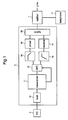
- Fig. 2 is a functional block diagram illustrating transceiver 11.
- Processor 20 has a function to execute the handshake step and initialization step prior to initiating data communication (SHOWTIME).
- Processor 20 also executes the later-described AGC during the data communication (SHOWTIME).
- the transmission process side of transceiver 11 includes Reed-Solomon encoder 21 that adds a redundancy bit for checking error, interleave unit 22 that sorts data to enable a burst error correction during Reed-Solomon decoding, Trellis encoder 23 that performs data convolution from a Trellis encoding, tone ordering unit 24 that lays out a bit number for each carrier, constellation encoder 25 that converts transmission data into constellation coordinates (topology), and IFFT unit 26 that performs an Inverse Fast Fourier Transform (hereafter referred to as IFFT) on data after the constellation encoding process.
- Reed-Solomon encoder 21 that adds a redundancy bit for checking error
- interleave unit 22 that sorts data to enable a burst error correction during Reed-Solomon decoding
- Trellis encoder 23 that performs data convolution from a Trellis encoding
- tone ordering unit 24 that lays out a bit number for each carrier
- constellation encoder 25 that
- the reception process side of transceiver 11 includes FFT unit 27 that performs a Fast Fourier Transform (hereafter referred to as FFT) on sampling data of the received signal, constellation decoder/FEQ unit 28 that decodes data from constellation data of the FFT output signal and corrects a topology on the constellation coordinates, tone de-ordering unit 29 that restores data laid out to each carrier after tone ordering process at the transmission side, Viterbi decoder 30 that performs Viterbi decoding on the received data, de-interleave unit 31 that restores data being resorted by the transmission side, and Reed-Solomon decoder 32 that deletes the redundancy bit added by the transmission side.
- constellation decoder/FEQ unit 28 performs an FEQ process using a sync symbol after initiating the data communication.
- Transceiver 11 is connected to host 12 via host interface (I/F) 34.
- FIG. 3 illustrates configurations of a bock related to the AGC (which is one of the functions of processor 20) and AFE 13.
- AFE 13 includes gain controller 101 that performs a gain control on a reception analog signal received from the line or a transmission analog signal output to the line, AD converter 102a that performs a sampling by synchronizing the received analog signal with a sampling clock, and DA converter 102b that converts the digital transmission analog signal into an analog signal.
- AGC controller 203 includes buffer 106 that stores the FFT output, maximum value retriever 107 that retrieves a maximum value from the FFT output (stored by buffer 106), integration filter 108 that performs a predetermined integral calculation on the maximum value retrieved by maximum value retriever 107, and gain control instructor 109 that determines the need of the gain control by gain controller 101, from the output of integration filter 108.
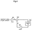
- Fig. 4 is a block diagram illustrating a configuration of integration filter 108.
- Integration filter 108 multiplies the maximum carrier energy amount (retrieved by maximum value retriever 107) by 0.1 using multiplier 301, which is referred to as value A, and outputs value A to adder 302.
- integration filer 108 multiplies value B (stored in inner register 303) by 0.9 using multiplier 304, which is referred to as value B', and outputs value B' to adder 302.
- integration filter 108 uses adder 302 to add value A (input from multiplier 301) and value B' (input from multiplier 304), which is referred to as value B, and outputs value B to inner register 303.
- This value B is stored within inner register 303.
- Fig. 5 is a flowchart illustrating an operation of the above-described configuration according to the embodiment of the present invention.
- the ATU-R operation is used, however, the invention can also be applied to the ATU-C.
- Step S1 initialization sequence is performed.
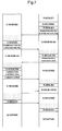
- Figs. 6 and 7 illustrate signals and timings used during the initialization sequence.
- the left side is the ATU-C (so-called “center"), and the right side is the ATU-R (so-called "remote").
- the ATU-C transmits three types of SEGUE signals: C-SEGUE1; C-SEGUE2; and C-SEGUE-RA, each of which is followed by information transmissions such as C-RATES, C-MSG, etc.
- C-SEGUE3 is transmitted at the final stage of the initialization sequence, data communication (SHOWTIME) is started.
- SHOWTIME data communication
- the ATU-R transmits four types of SEGUE signals: R-SEGUE1; R-SEGUE2; R-SEGUE-RA; and R-SEGUE4, each of which (excluding R-SEGUE1) is followed by information transmissions such as R-RATES, R-MSG, etc.
- R-SEGUE5 is transmitted at the final stage of the initialization sequence, data communication (SHOWTIME) is started.
- a counter starts counting the symbol number received after starting the SHOWTIME (Step S2).
- the SHOWTIME there are periodical phases called sync symbols.
- the counter that counts the symbol number is started.
- a sync symbol is a simple symbol similar to REVERB signal that is transmitted during the initialization. While the REVERB signal is random from a frequency perspective, each carrier has the same eye pattern. Similarly, it is decided that a sync symbol is transmitted with a plurality of carriers, each carrier always having 2 bit data for transmission. Therefore, sync symbol is modulated into one of four transmission points mutually having 90 degrees from one another for transmission, as illustrated in Fig. 10 (a). Further, a sync symbol has a determined transmission point to be modulated into, out of four standard points (transmission points) for each carrier.
- the correction is made in the direction of amplitude so that the reception symbol is proximate to the target standard point.
- calculation load is limited to an allowable range.
- the target standard point for each carrier is known, the calculation amount is further lightened. Even when the symbol reception point is received at a proximity of another standard point (which is not the target standard point), as shown in Fig. 10 (b), it is possible to appropriately perform the AGC so that the reception symbol is brought closer to the targeted standard point, since the target standard point is already known.
- each carrier is loaded with as big bit number as possible in order to improve the transfer efficiency. Therefore, when a bit number of a symbol increases, such as 4-5 bits per symbol, the standard number of the target standard points for the AGC will be increased, e.g., 16 points and 32 points. Therefore, the calculation load will exceed the allowable range.
- the AGC and FEQ processes can be performed with a minimum calculation amount during the SHOWTIME period, when a sync symbol is used for every N symbol.
- N the number of received symbols
- the reception symbol is processed and the reception symbol counter is increased (steps S4 and S5).
- the above process is repeated every time there is a symbol reception.
- the AGC and FEQ processes are performed using the sync symbol (steps S6 and S7).
- AGC is performed at step S6, using the sync symbol.
- a modulation signal of the sync symbol is sampled by AD converter 102a of AFE 13.
- FFT unit 27 performs a fast Fourier transform.
- signal values of all carriers can be obtained as a form of constellation for each carrier (as coordinate values in complex plane coordinates).
- carrier signal value (energy value) for each symbol is shown as one coordinate point on the R-I (Real-Imaginary) plane, and such (R, I) coordinates corresponding to each carrier are stored in buffer 106.
- maximum value retriever 107 retrieves a carrier energy amount having the maximum value, based on the (R, I) coordinates, among energy amounts for multiple carriers within a sync symbol.
- the distance from the origin point to (R, I) coordinates for each sampling data on the R-I planes are equivalent to the energy amount for each carrier. Therefore, by comparing the distance from the origin point to (R, I) coordinates for each sampling data, maximum value retriever 107 can retrieve the carrier energy amount having the maximum value.
- Integration filter 108 performs a predetermined integration calculation on the carrier energy amount of the maximum value, which is retrieved by maximum value retriever 107.
- Gain control indicator 109 compares value B (obtained from the integral calculation) with the target range. When value B is greater than the upper limit value of the target range, a gain control is instructed for gain controller 101 to decrease the energy amount of the received analog signal. For example, all carrier energy amounts from the future input signals are decreased by 1db. Conversely, when value B is smaller than the lower limit value of the target range, gain control is instructed for gain controller 101 to raise the energy amount of the receiving analog signals (e.g., raising all carrier energy amounts from the future input signals by 1db). In addition, when value B is within the target range, no gain control is instructed.
- Fig. 9 illustrates frequency characteristics of the REVERB signal after the gain control.
- the FEQ process is performed by constellation decoder/FEQ unit 28 using a sync symbol.
- Constellation decoder/FEQ unit 28 corrects a gain and topology in order to move the reception point to the standard point, based from the constellation of the received symbol. Since the sync symbol forms a 2 bit eye pattern, as shown in Fig. 10, it is possible to have a much simpler calculation of which of the four standard points the reception point belongs to, compared to having 32 standard points, for example.
- the FEQ process is performed using the sync symbol having 2 bit eye pattern. Since the calculation amount is small, it is possible to perform the FEQ process even during the SHOWTIME.
- step S8 When the AGC and FEQ processes are finished using the sync symbol, the counter is reset (step S8), and the control proceeds to step S2.
- the preset invention is not limited to the method but can be applied to any communication methods that employ the multi-carrier method and periodically (or at a known timing) transmit signals equivalent to a sync symbol during the data communication.
- the signal equivalent to the sync symbol should be detectable by the reception side, modulated by the multi-carrier method, and having few layout bit number (calculation amount that can be processed by the DSP for a 1 symbol period).
Landscapes
- Engineering & Computer Science (AREA)
- Computer Networks & Wireless Communication (AREA)
- Signal Processing (AREA)
- Telephonic Communication Services (AREA)
- Cable Transmission Systems, Equalization Of Radio And Reduction Of Echo (AREA)
Applications Claiming Priority (2)
| Application Number | Priority Date | Filing Date | Title |
|---|---|---|---|
| JP2002160494A JP2004007267A (ja) | 2002-05-31 | 2002-05-31 | Dslモデム装置及びdsl通信における通信制御方法 |
| JP2002160494 | 2002-05-31 |
Publications (1)
| Publication Number | Publication Date |
|---|---|
| EP1367791A2 true EP1367791A2 (fr) | 2003-12-03 |
Family
ID=29417276
Family Applications (1)
| Application Number | Title | Priority Date | Filing Date |
|---|---|---|---|
| EP03012539A Withdrawn EP1367791A2 (fr) | 2002-05-31 | 2003-06-02 | Controle de gain pour modem multiporteuse |
Country Status (4)
| Country | Link |
|---|---|
| US (1) | US20030223459A1 (fr) |
| EP (1) | EP1367791A2 (fr) |
| JP (1) | JP2004007267A (fr) |
| KR (1) | KR100575565B1 (fr) |
Cited By (1)
| Publication number | Priority date | Publication date | Assignee | Title |
|---|---|---|---|---|
| WO2009153282A1 (fr) * | 2008-06-20 | 2009-12-23 | Nokia Siemens Networks Oy | Procédé et dispositif de traitement de données, système de communication comprenant un tel dispositif, émetteur et récepteur |
Families Citing this family (3)
| Publication number | Priority date | Publication date | Assignee | Title |
|---|---|---|---|---|
| JP2004007269A (ja) | 2002-05-31 | 2004-01-08 | Panasonic Communications Co Ltd | Dslモデム装置及びdsl通信におけるイニシャライズ方法 |
| JP2005064743A (ja) * | 2003-08-08 | 2005-03-10 | Matsushita Electric Ind Co Ltd | Adslモデム装置及びその通信方法 |
| KR200453618Y1 (ko) * | 2010-01-27 | 2011-05-17 | 주식회사 월드웰 | 변압기용 전선 접속부재 |
Family Cites Families (8)
| Publication number | Priority date | Publication date | Assignee | Title |
|---|---|---|---|---|
| JP2712212B2 (ja) * | 1987-12-23 | 1998-02-10 | ソニー株式会社 | 同期信号の検出及び保護回路 |
| US4866395A (en) * | 1988-11-14 | 1989-09-12 | Gte Government Systems Corporation | Universal carrier recovery and data detection for digital communication systems |
| SE9302453L (sv) * | 1993-07-20 | 1994-10-17 | Telia Ab | Förfarande och anordning för synkronisering i digitalt transmissionssystem av typen OFDM |
| JP3503722B2 (ja) * | 1996-05-17 | 2004-03-08 | パイオニア株式会社 | 多値ディジタル伝送システム |
| US6466629B1 (en) * | 1996-09-02 | 2002-10-15 | Stmicroelectronics N.V. | Multi-carrier transmission systems |
| US7020218B2 (en) * | 2001-06-18 | 2006-03-28 | Arnesen David M | Sliding-window transform with integrated windowing |
| US7227914B2 (en) * | 2001-12-12 | 2007-06-05 | Harris Corporation | Automatic gain control for digital signals |
| US7130354B1 (en) * | 2002-05-02 | 2006-10-31 | 3Com Corporation | Method and apparatus for improving error control properties for encoding and decoding data |
-
2002
- 2002-05-31 JP JP2002160494A patent/JP2004007267A/ja active Pending
-
2003
- 2003-03-27 US US10/397,254 patent/US20030223459A1/en not_active Abandoned
- 2003-05-30 KR KR1020030034982A patent/KR100575565B1/ko not_active Expired - Fee Related
- 2003-06-02 EP EP03012539A patent/EP1367791A2/fr not_active Withdrawn
Cited By (2)
| Publication number | Priority date | Publication date | Assignee | Title |
|---|---|---|---|---|
| WO2009153282A1 (fr) * | 2008-06-20 | 2009-12-23 | Nokia Siemens Networks Oy | Procédé et dispositif de traitement de données, système de communication comprenant un tel dispositif, émetteur et récepteur |
| EP2136522A1 (fr) * | 2008-06-20 | 2009-12-23 | Nokia Siemens Networks Oy | Procédé et dispositif de traitement de données, système de communication comprenant un tel dispositif, transmetteur et récepteur |
Also Published As
| Publication number | Publication date |
|---|---|
| KR20030094072A (ko) | 2003-12-11 |
| KR100575565B1 (ko) | 2006-05-02 |
| JP2004007267A (ja) | 2004-01-08 |
| US20030223459A1 (en) | 2003-12-04 |
Similar Documents
| Publication | Publication Date | Title |
|---|---|---|
| CN1951048B (zh) | 正交频分复用接收装置及正交频分复用接收方法 | |
| JP2001060936A (ja) | 直交周波数分割多重信号の送受信方法及びその装置 | |
| CN100385797C (zh) | 峰值抑制方法以及数据传送装置 | |
| CN100571085C (zh) | Ofdm接收装置以及数据解调方法 | |
| US20090245092A1 (en) | Apparatus, processes, and articles of manufacture for fast fourier transformation and beacon searching | |
| JP3717363B2 (ja) | xDSLトランシーバ | |
| CN100409600C (zh) | 接收装置和接收方法 | |
| EP1367791A2 (fr) | Controle de gain pour modem multiporteuse | |
| KR20100126568A (ko) | 수신기 | |
| JP2009239549A (ja) | Ofdm送信装置、およびofdm送信方法 | |
| JP3534020B2 (ja) | マルチキャリア変調方式用復調回路 | |
| JP2000228657A (ja) | 受信装置 | |
| US20040017849A1 (en) | ADSL modem apparatus and communication method for the ADSL modem apparatus | |
| JP3992908B2 (ja) | 直交周波数分割多重変調方式を用いた伝送装置 | |
| US20050036540A1 (en) | DSL modem apparatus and communication control method | |
| EP1509017A2 (fr) | Modem DSL et méthode de contrôle de communication | |
| US20030223483A1 (en) | DSL modem apparatus and reception method for DSL communication | |
| EP1278328B1 (fr) | Modem avec dispositif de commande de gain | |
| EP1508976A1 (fr) | Modem DSL et méthode de contrôle de communication | |
| US20050025227A1 (en) | ADSL modem apparatus and communication method thereof | |
| US20040022310A1 (en) | ADSL modem apparatus and ADSL modem communication method | |
| JP2002217862A (ja) | Qam復号装置 | |
| JP2000307544A (ja) | 受信装置 | |
| CN118646618A (zh) | 一种适用于大频偏条件的dft-s-ofdm波形的信道估计方法 | |
| JP2004247852A (ja) | マルチキャリア受信装置 |
Legal Events
| Date | Code | Title | Description |
|---|---|---|---|
| PUAI | Public reference made under article 153(3) epc to a published international application that has entered the european phase |
Free format text: ORIGINAL CODE: 0009012 |
|
| 17P | Request for examination filed |
Effective date: 20030910 |
|
| AK | Designated contracting states |
Kind code of ref document: A2 Designated state(s): AT BE BG CH CY CZ DE DK EE ES FI FR GB GR HU IE IT LI LU MC NL PT RO SE SI SK TR |
|
| AX | Request for extension of the european patent |
Extension state: AL LT LV MK |
|
| STAA | Information on the status of an ep patent application or granted ep patent |
Free format text: STATUS: THE APPLICATION HAS BEEN WITHDRAWN |
|
| 18W | Application withdrawn |
Effective date: 20060809 |