EP1370431B1 - Structural member for a suspension of a motor vehicle and method for its production - Google Patents
Structural member for a suspension of a motor vehicle and method for its production Download PDFInfo
- Publication number
- EP1370431B1 EP1370431B1 EP02702667A EP02702667A EP1370431B1 EP 1370431 B1 EP1370431 B1 EP 1370431B1 EP 02702667 A EP02702667 A EP 02702667A EP 02702667 A EP02702667 A EP 02702667A EP 1370431 B1 EP1370431 B1 EP 1370431B1
- Authority
- EP
- European Patent Office
- Prior art keywords
- side plate
- connection means
- limb
- plate portion
- structural member
- Prior art date
- Legal status (The legal status is an assumption and is not a legal conclusion. Google has not performed a legal analysis and makes no representation as to the accuracy of the status listed.)
- Expired - Lifetime
Links
- 239000000725 suspension Substances 0.000 title claims abstract description 15
- 238000004519 manufacturing process Methods 0.000 title claims description 16
- 238000000034 method Methods 0.000 title claims description 16
- 239000000463 material Substances 0.000 claims abstract description 5
- 238000007493 shaping process Methods 0.000 claims description 2
- 230000002093 peripheral effect Effects 0.000 claims 3
- 239000011265 semifinished product Substances 0.000 abstract description 17
- 238000005304 joining Methods 0.000 description 10
- 238000003466 welding Methods 0.000 description 7
- 238000003780 insertion Methods 0.000 description 3
- 230000037431 insertion Effects 0.000 description 3
- 239000000853 adhesive Substances 0.000 description 2
- 230000001070 adhesive effect Effects 0.000 description 2
- 239000000047 product Substances 0.000 description 2
- 239000007858 starting material Substances 0.000 description 2
- OKTJSMMVPCPJKN-UHFFFAOYSA-N Carbon Chemical compound [C] OKTJSMMVPCPJKN-UHFFFAOYSA-N 0.000 description 1
- 229920000271 Kevlar® Polymers 0.000 description 1
- 229910000831 Steel Inorganic materials 0.000 description 1
- 239000004411 aluminium Substances 0.000 description 1
- 229910052782 aluminium Inorganic materials 0.000 description 1
- XAGFODPZIPBFFR-UHFFFAOYSA-N aluminium Chemical compound [Al] XAGFODPZIPBFFR-UHFFFAOYSA-N 0.000 description 1
- 229910052799 carbon Inorganic materials 0.000 description 1
- 238000009826 distribution Methods 0.000 description 1
- 239000011521 glass Substances 0.000 description 1
- 239000004761 kevlar Substances 0.000 description 1
- 230000014759 maintenance of location Effects 0.000 description 1
- 229910052751 metal Inorganic materials 0.000 description 1
- 239000002184 metal Substances 0.000 description 1
- 239000004033 plastic Substances 0.000 description 1
- 229920003023 plastic Polymers 0.000 description 1
- 238000003825 pressing Methods 0.000 description 1
- 125000006850 spacer group Chemical group 0.000 description 1
- 239000010959 steel Substances 0.000 description 1
- 239000004616 structural foam Substances 0.000 description 1
- 229920001169 thermoplastic Polymers 0.000 description 1
- 229920001187 thermosetting polymer Polymers 0.000 description 1
- 239000004416 thermosoftening plastic Substances 0.000 description 1
Images







Classifications
-
- B—PERFORMING OPERATIONS; TRANSPORTING
- B60—VEHICLES IN GENERAL
- B60G—VEHICLE SUSPENSION ARRANGEMENTS
- B60G7/00—Pivoted suspension arms; Accessories thereof
- B60G7/001—Suspension arms, e.g. constructional features
-
- B—PERFORMING OPERATIONS; TRANSPORTING
- B60—VEHICLES IN GENERAL
- B60G—VEHICLE SUSPENSION ARRANGEMENTS
- B60G2206/00—Indexing codes related to the manufacturing of suspensions: constructional features, the materials used, procedures or tools
- B60G2206/01—Constructional features of suspension elements, e.g. arms, dampers, springs
- B60G2206/012—Hollow or tubular elements
-
- B—PERFORMING OPERATIONS; TRANSPORTING
- B60—VEHICLES IN GENERAL
- B60G—VEHICLE SUSPENSION ARRANGEMENTS
- B60G2206/00—Indexing codes related to the manufacturing of suspensions: constructional features, the materials used, procedures or tools
- B60G2206/01—Constructional features of suspension elements, e.g. arms, dampers, springs
- B60G2206/10—Constructional features of arms
Definitions
- the present invention relates to a structural member for a suspension of a motor vehicle, in particular for a triangular arm having a box-like structure, as specified in the preamble of claim 1, and further to a method for the production of such a member, as specified in the preamble of claim 8.
- triangular arm is to be intended as referring to an arm provided with three points of connection defining a triangle.
- Members having a box-like structure and adapted to be used as triangular swing arms in motor-vehicle suspensions are currently produced by arranging facing each other two separate portions, or half-shells, obtained in a conventional manner by means of pressing operations, and then proceeding with the fixing of such portions, for example by means of welding along at least a part of their perimeter.
- Members of this type are disclosed for instance in JP 06 143953 and US-A-5 362 090.
- GB-A-2 063 783 discloses a suspension member comprising a folded single sheet of metal and adapted to be coupled at its opposite ends to a wheel assembly and to a vehicle frame, respectively.
- a triangular arm of a motor-vehicle suspension comprises a structural member 2 with box-like structure, of substantially rectangular section, consisting of a first and a second portion 3 and 4 in the form of a respectively upper and lower half-shell. Said portions 3 and 4 are disposed facing each other with respect to a horizontal plane ⁇ , which is advantageously parallel to the planes in which they substantially i.e.
- the structural member 2 of the suspension arm 1 comprises a straight limb 5, constituted in part by the aforesaid first portion 3 and in part by the second portion 4.
- the limb 5 has a substantially vertical lateral face 5' (visible in Figure 2), the upper edge 16 and lower edge 17 of which correspond to fold lines of the product.
- a second curved limb 6 Connected to the limb 5, on the opposite side from the face 5', there is a second curved limb 6, also constituted in part by the upper portion 3 and in part by the lower portion 4 of the member 2.
- the limbs 5 and 6 are of such dimensions and shape and are so arranged that their free ends are located at the vertices of a substantially right-angled triangle lying in a plane preferably coplanar with the plane n.
- the two facing portions 3 and 4 of the structural member 2 have joining edges 7a, 7b, 8a and 8b (the latter not visible in Figures 1 and 2), where the numerals 7 and 8 refer to the lateral faces of the arm having in plan substantially a concave and convex profile, respectively, while the two letter indices a and b refer to the two portions, upper 3 and lower 4, respectively.
- said edges are of the superposed type: that is to say, they have the same shape, substantially flat and parallel to the plane in which lies the shaped element constituting the initial semi-finished product. Consequently, after the operations of folding over the two plate portions of the semi-finished product along the lines 16 and 17, which impart the definitive spatial arrangement to the two portions 3 and 4 of the structural member 2, the joining edges are facing one another and superposed with respect to the horizontal plane ⁇ , and can thus be rigidly connected to each other, preferably by means of seam welding.
- any joining edges can assume various forms and arrangements, for example:
- the fixing edges 7a, 7b, 8a and 8b ( Figures 1 and 2) and before the free end of the curved limb 6, where a cylindrical seat 9 is provided to receive an intermediate connection device, such as a bush 18 with vertical axis (not shown).
- the seat 9 is obtained by the superposition of two circular holes 9a and 9b, produced respectively in the upper portion 3 and lower portion 4 of the structural member 2, so that they are coaxial with each other at the end of the operations of folding along the lines 16 and 17. In the region of the limb 6 surrounding the seat 9, the two portions 3 and 4 of the member 2 are therefore simply facing one another.
- the holes 9a and 9b which form the seat 9 advantageously have respective circumferential edges 10a and 10b turned vertically towards the internal cavity of the structural member 2 and adapted to ensure centring and locking of the intermediate connection device (bush 18) between the two facing portions 3 and 4.
- a further cylindrical seat 24 with vertical axis is formed, also adapted to the fixing of an intermediate connection device such as a bush.
- Said seat is obtained by superposing two circular holes 24a and 24b, produced respectively in the upper portion 3 and the lower portion 4 of the structural member, so that they are coaxial with each other at the end of the operations of folding along the lines 16 and 17.
- the holes 24a and 24b also have respective circumferential edges 25a and 25b, in this case turned vertically towards the outside of the structural member 2, instead of towards the internal cavity, but having a similar function.
- One of the two ends of the straight limb 5 has two appendages 11a and 11b, each associated with one of the two facing portions 3 and 4, being suitably shaped and opened out for stable retention of a bush 12 with horizontal axis, by engaging with the lateral cylindrical surface of the latter.
- each pair of apertures preferably circular in shape, thus defines a cylindrical seat 13 into which is inserted a bolt for fixing a bracket member 20 carrying an articulation support 14.
- the locking of the bracket member 20, which extends for part of its length inside the internal cavity of the box-like structure at one end of the limb 5, can be effected in various other ways, for example by rivetting, as is well known to an expert in the field.
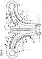
- Figure 3 shows a plan view of the starting semi-finished product, consisting of a shaped element 2' with two plate portions 3' and 4', integrally produced therewith and corresponding respectively to the two portions 3 and 4 in the shape of a half-shell of the box-like member.
- the semi-finished product 2' is obtained by blanking from a sheet of steel, aluminium or plastics material (of the thermoplastic or thermosetting type, if necessary reinforced by the addition of glass, carbon or Kevlar fibres).
- the starting material in sheet form can have a constant or variable thickness (also termed multi-layer).
- the sheet is of a particular type, produced appropriately on the basis of the type of application, which has areas of different thickness according to the nature and distribution of the stresses to which the structural member is subject in operation.
- the starting semi-finished product has a shape symmetrical with respect to an axis 15, as can be clearly seen in Figure 3. Still with reference to said figure, it is also possible to identify for each of the two plate portions 3' and 4' the details of the finished product described above, that is to say, the two limbs, straight 5 and curved 6, the joining edges 7a, 7b, 8a and 8b, the circular holes 9a, 9b and 24a, 24b respectively defining the cylindrical seats with vertical axis 9 and 24, the shaped appendages 11a and 11b for retaining the bush 12 with horizontal axis, and the holes 13a and 13b for the engagement of the bracket member 20 carrying the articulation support 14.
- the first operation consists in blanking the starting material in sheet form to obtain a semi-finished product 2' ( Figure 3) suitably shaped so that its two integral plate portions 3' and 4' correspond to the development in plan view of the half-shell portions 3 and 4 of the structural member 2.
- a first series of shaping and folding operations are carried out which essentially involve the joining edges 7a, 7b, 8a and 8b, the edges 10a, 10b and 25a, 25b of the circular holes 9a, 9b and respectively 24a, 24b, and the appendages 11a and 11b, to impart the final half-shell shape to the plate portions 3' and 4'.
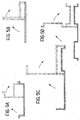
- the two portions 3 and 4 of the structural member 2 are in the shape of concave half-shells, that is to say, the respective cross-sections in planes perpendicular to the axis of symmetry 15 have a substantially concave profile. It is possible, however, to arrange said portions so as to obtain different combinations of shape of the two half-shells, such as, for example, concave/flat, concave/convex and convex/convex ( Figures 5B to 5D) .
- a successive step of the production method according to the invention consists in folding over the shaped element 2' of Figure 3 along at least one predetermined line, so as to dispose the respective portions 3 and 4 thereof substantially facing each other.
- the semi-finished product 2' is subjected in sequence to a first and a second folding operation at right-angles, respectively along the lines 17 and 16, parallel to each other and symmetrical with respect to the axis 15, so as to bring together the inner faces of the joining edges 7a, 7b, 8a and 8b.
- each of the folding operations is carried out by using, for example, a core of prismatic shape (not shown) the length of which is equal at least to that of the folding line and the cross-section of which forms at least one angle equal to the desired folding angle.
- Folding is thus carried out at first by placing one of the folding faces of the core (that is to say, one of the faces of the core forming the desired folding angle) on the inner face of one of the two plate portions of the semi-finished product, so that the edge corresponding to the vertex of said angle is positioned at the folding line on the semi-finished product, and then rotating the other plate portion of the semi-finished product about the predetermined folding line until its inner face abuts the second of the aforesaid folding faces.
- FIGS 7A and 7B illustrate two different solutions for the mounting of the bush 18 with vertical axis in the cylindrical seat 9.
- the seat 9 is obtained by the superposition of the two circular holes 9a and 9b, formed in the plate portions 3' and 4' of the semi-finished product 2' in a position such that the holes are disposed coaxially with each other following the aforesaid folding operations.
- said holes are preferably provided with circumferential edges 10a and 10b folded over towards the inside of the member 2 perpendicularly to the plane in which the sheet lies.
- FIG. 7A illustrates a bush 18 with vertical axis, used as an intermediate connection device, provided with a flange 19 adapted to function as end stop for the insertion into the seat 9.
- edges are provided, as in the preferred exemplary embodiment considered here, after folding, said edges are then fixed to each other, in a manner described previously with reference to Figures 6A to 6F (seam welding or spot welding, rivetting, securing by adhesive, or clinching).
- the structural member 2 is substantially rectangular in cross-section. It is possible, however, to produce box-like structures with cross-sections of different shape, either closed, such as for example a triangular shape, teardrop-shape or recumbent T-shape ( Figures 8A to 8C), or open, such as for example a C-shape ( Figure 8D).
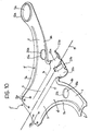
- FIGS 9 and 10 illustrate a further preferred embodiment of the invention, in which the same reference numerals have been assigned to parts and elements similar or identical to those illustrated in the preceding figures.
- the semi-finished product 2' therefore no longer has a shape symmetrical with respect to the axis 15 ( Figure 10), since the lateral development of the curved limb 6 of the plate portion 4' is interrupted at an edge 6', before forming an end portion corresponding to that of the other plate portion in which the hole 9b is formed.
- Said solution makes it possible to reduce the production costs further, owing to the minimisation of the scrap caused by the initial blanking operation.
- Another advantage lies in the fact that the production of the cylindrical seat 9 by means of a single hole 9a or 9b in one of the two portions 3 and 4 of the structural member 2, instead of by means of both the holes 9a and 9b in the two portions 3 and 4, avoids the need to define tight limits of tolerance in the mutual positioning of said holes, thus further contributing to the reduction of the costs of manufacture of the member.
- FIG. 22 Another difference between this second preferred embodiment and the first lies in the arrangement for fixing the bush 12 with horizontal axis.
- fixing is ensured by a circumferentially closed seat 22, comprised between two semicircular appendages 22a and 22b, which extend longitudinally from the straight limbs 5 of the two portions 3 and 4 of the member 2.
- the appendages 22a and 22b advantageously have joining edges 23a and 23b respectively, which may have shapes and arrangements of the same type as those described with regard to the edges 7a, 7b, 8a, 8b for joining the limbs 5 and 6 of the two facing portions 3 and 4.
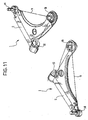
- Figure 11 shows how the structural member 2 can be used according to the invention to form both the left-hand and right-hand arms of the same motor vehicle suspension, without the need to differentiate the designs and methods of production of the member intended for the left-hand arm with respect to that intended for the right-hand arm.
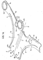
- the seat 26, which is capable of receiving a connection device 28, such as a bush ( Figure 12), is formed in a similar manner to the cylindrical seat 9 at the end of the curved limb 6. It in fact comprises a single circular hole 26a, advantageously provided with a circumferential edge 27a, formed in the upper portion 3 of the member 2, as can be clearly observed in particular in Figures 13B and 13D, which show two sectional views of the member 2 in two different planes passing through the axis of the seat 26.
Landscapes
- Engineering & Computer Science (AREA)
- Mechanical Engineering (AREA)
- Vehicle Body Suspensions (AREA)
- Automobile Manufacture Line, Endless Track Vehicle, Trailer (AREA)
- Body Structure For Vehicles (AREA)
- Extrusion Of Metal (AREA)
Applications Claiming Priority (3)
| Application Number | Priority Date | Filing Date | Title |
|---|---|---|---|
| IT2001TO000253A ITTO20010253A1 (it) | 2001-03-16 | 2001-03-16 | Elemento strutturale per una sospensione di un autoveicolo e procedimento per la sua realizzazione. |
| ITTO20010253 | 2001-03-16 | ||
| PCT/IB2002/000756 WO2002074562A2 (en) | 2001-03-16 | 2002-03-12 | Structural member for a suspension of a motor vehicle and method for its production |
Publications (2)
| Publication Number | Publication Date |
|---|---|
| EP1370431A2 EP1370431A2 (en) | 2003-12-17 |
| EP1370431B1 true EP1370431B1 (en) | 2007-05-09 |
Family
ID=11458703
Family Applications (1)
| Application Number | Title | Priority Date | Filing Date |
|---|---|---|---|
| EP02702667A Expired - Lifetime EP1370431B1 (en) | 2001-03-16 | 2002-03-12 | Structural member for a suspension of a motor vehicle and method for its production |
Country Status (14)
| Country | Link |
|---|---|
| US (1) | US20040135337A1 (cs) |
| EP (1) | EP1370431B1 (cs) |
| JP (2) | JP4397589B2 (cs) |
| AT (1) | ATE361847T1 (cs) |
| AU (1) | AU2002236165A1 (cs) |
| BR (1) | BR0208484B1 (cs) |
| CZ (1) | CZ300490B6 (cs) |
| DE (1) | DE60220031T2 (cs) |
| ES (1) | ES2287247T3 (cs) |
| HU (1) | HU228712B1 (cs) |
| IT (1) | ITTO20010253A1 (cs) |
| PL (1) | PL209157B1 (cs) |
| RU (1) | RU2281207C2 (cs) |
| WO (1) | WO2002074562A2 (cs) |
Cited By (3)
| Publication number | Priority date | Publication date | Assignee | Title |
|---|---|---|---|---|
| DE102007060963B3 (de) * | 2007-12-14 | 2009-04-09 | Benteler Automobiltechnik Gmbh | Verfahren zur Herstellung einer Achskomponente |
| DE102010028400A1 (de) | 2010-04-30 | 2011-11-03 | Ford Global Technologies, Llc | Querlenker in Schalenbauweise |
| DE102008015393C5 (de) * | 2008-03-20 | 2015-11-19 | Gmf Umformtechnik Gmbh | Verfahren zum Herstellen eines von einer einteiligen Blechschale gebildeten, im Querschnitt im Wesentlichen U-förmigen Lenkers für eine Kraftfahrzeug-Mehrlenkerachse |
Families Citing this family (54)
| Publication number | Priority date | Publication date | Assignee | Title |
|---|---|---|---|---|
| ITTO20010253A1 (it) * | 2001-03-16 | 2002-09-16 | Sistemi Sospensioni Spa | Elemento strutturale per una sospensione di un autoveicolo e procedimento per la sua realizzazione. |
| US20060151970A1 (en) * | 2002-05-31 | 2006-07-13 | Magna International Inc. | Hydroformed control arm |
| US7163219B2 (en) * | 2002-10-16 | 2007-01-16 | Alcoa Inc. | Control arm for motor vehicle suspension system |
| DE60304709T2 (de) * | 2003-07-07 | 2006-12-21 | Zf Friedrichshafen Ag | Kraftfahrzeugaufhängungslenker |
| DE10334192A1 (de) * | 2003-07-26 | 2005-02-10 | Bayerische Motoren Werke Ag | Lenker für eine Fahrzeug-Radaufhängung |
| WO2005087520A1 (de) | 2004-03-09 | 2005-09-22 | Zf Friedrichshafen Ag | Führungslenker für die radaufhängung eines kraftfahrzeuges |
| DE102004016723A1 (de) * | 2004-04-05 | 2005-10-13 | Volkswagen Ag | Radführender Lenker, insbesondere für ein Nutzfahrzeug |
| JP4533739B2 (ja) * | 2004-12-28 | 2010-09-01 | ヒルタ工業株式会社 | ロアアーム |
| US7980576B2 (en) | 2005-08-17 | 2011-07-19 | Honda Motor Co., Ltd. | Vehicular suspension arm |
| DE102006028713B3 (de) | 2006-06-20 | 2007-11-22 | Thyssenkrupp Umformtechnik Gmbh | Verfahren zum Herstellen eines im Querschnitt U-förmigen Lenkers aus Blech für eine PKW-Mehrlenkerachse |
| DE202007001892U1 (de) | 2007-02-03 | 2008-06-12 | Hqm Sachsenring Gmbh | Gelenkstange |
| DE102007015615B4 (de) * | 2007-03-29 | 2012-07-19 | Zf Friedrichshafen Ag | Verbindungsstück zum gelenkigen Verbinden von im Fahrwerk eines Fahrzeugs angeordneten Bauelementen |
| KR20120013459A (ko) * | 2007-03-29 | 2012-02-14 | 닛산 지도우샤 가부시키가이샤 | 차량 서스펜션 장치 |
| DE102007026702B4 (de) * | 2007-06-06 | 2014-04-17 | Benteler Automobiltechnik Gmbh | Achskomponente |
| JP4692578B2 (ja) * | 2008-05-30 | 2011-06-01 | トヨタ自動車株式会社 | 車両のサスペンションアーム |
| JP5363065B2 (ja) * | 2008-11-05 | 2013-12-11 | 株式会社エフテック | 車両用l型サスペンションアーム |
| JP2010111226A (ja) * | 2008-11-05 | 2010-05-20 | F Tech:Kk | 車両用l型サスペンションアーム |
| DE102008056271B4 (de) * | 2008-11-06 | 2021-02-04 | Volkswagen Aktiengesellschaft | Querlenker in Blechkonstruktion |
| FR2938470B1 (fr) * | 2008-11-20 | 2011-01-14 | Peugeot Citroen Automobiles Sa | Bras de suspension monobloc de vehicule automobile |
| DE102010007946A1 (de) * | 2010-02-12 | 2011-08-18 | Benteler Automobiltechnik GmbH, 33102 | Querlenker mit Lagerzapfen und Verfahren zur Herstellung eines Querlenkers |
| DE102010007944A1 (de) * | 2010-02-12 | 2011-08-18 | Benteler Automobiltechnik GmbH, 33102 | Querlenker und Verfahren zur Herstellung eines Querlenkers |
| DE102010024634A1 (de) * | 2010-06-22 | 2011-12-22 | Benteler Automobiltechnik Gmbh | Kraftfahrzeuglenker |
| JP2012025226A (ja) * | 2010-07-21 | 2012-02-09 | Kubota Corp | サスペンション用アーム |
| US20120098228A1 (en) * | 2010-10-20 | 2012-04-26 | Multimatic Inc. | Stamped arm control |
| DE102010043038A1 (de) * | 2010-10-28 | 2012-05-03 | Zf Friedrichshafen Ag | Verfahren zur Herstellung eines Fahrwerkbauteils |
| KR101211419B1 (ko) * | 2010-10-29 | 2012-12-12 | 주식회사화신 | 자동차용 로워암 |
| KR101211418B1 (ko) * | 2010-10-29 | 2012-12-12 | 주식회사화신 | 자동차용 로워암 |
| JP5299470B2 (ja) * | 2011-05-16 | 2013-09-25 | 日産自動車株式会社 | サスペンション構造、サスペンションリンク形成方法 |
| DE102011053222B4 (de) * | 2011-09-02 | 2024-10-31 | Gmf Umformtechnik Gmbh | Querlenker aus faserverstärktem Kunststoff für eine Radaufhängung eines Fahrzeuges und Verfahren zu dessen Herstellung |
| FR2991633A1 (fr) * | 2012-06-06 | 2013-12-13 | Peugeot Citroen Automobiles Sa | Triangle constitutif d'un train roulant equipant un vehicule automobile |
| DE102012104909A1 (de) * | 2012-06-06 | 2013-12-12 | Benteler Automobiltechnik Gmbh | Querlenker sowie Verfahren zum Herstellen des Querlenkers |
| CN102967195A (zh) * | 2012-10-30 | 2013-03-13 | 芜湖可挺汽车底盘件有限公司 | 一种用于轿车三角臂检测的固定限位装置 |
| DE102013003145B4 (de) * | 2013-02-25 | 2021-07-08 | Audi Ag | Blechlenker für die Radaufhängung eines Kraftfahrzeugs, Radaufhängung sowie Kraftfahrzeug |
| WO2014147754A1 (ja) * | 2013-03-19 | 2014-09-25 | 株式会社ヨロズ | サスペンションリンク及びその製造方法 |
| DE102013011589A1 (de) * | 2013-07-11 | 2015-01-15 | Audi Ag | Fahrwerkslenker für ein Fahrzeug und Verfahren zur Herstellung eines Fahrwerkslenkers |
| KR101488207B1 (ko) * | 2014-02-10 | 2015-01-30 | 이형광 | 자동차용 로워암 |
| DE102014220443B4 (de) * | 2014-10-09 | 2021-12-23 | Ford Global Technologies, Llc | Lenker für die Anbindung eines Fahrzeugrads an ein Fahrzeug sowie Fahrzeugradaufhängung |
| DE102014118363A1 (de) * | 2014-12-10 | 2016-06-16 | Benteler Automobiltechnik Gmbh | Verfahren zur Herstellung eines Lenkers und Lenker |
| US9446640B1 (en) * | 2015-10-05 | 2016-09-20 | Mike Smith | Box A-frame suspension arm |
| WO2017115932A1 (ko) * | 2015-12-30 | 2017-07-06 | 주식회사 일진 | 차량용 하이브리드 현가암 및 그 제조방법 |
| DE102016203853A1 (de) * | 2016-03-09 | 2017-09-14 | Zf Friedrichshafen Ag | Fahrwerklenker |
| FR3060067B1 (fr) * | 2016-12-14 | 2019-01-25 | Renault S.A.S | Assemblage d'une premiere piece creuse et d'une deuxieme piece et procede d'assemblage associe |
| DE102017109996B4 (de) * | 2017-05-09 | 2019-01-17 | Benteler Automobiltechnik Gmbh | Radlenker mit einem ersten und zweiten Profilkörper |
| DE102017212746B4 (de) * | 2017-07-25 | 2025-04-24 | Ford Global Technologies, Llc | Hybridlenker einer Radaufhängung mit integrierter Federfunktion |
| DE102019205096B4 (de) | 2019-04-09 | 2024-09-26 | Audi Ag | Lenker für eine Radaufhängung eines Kraftfahrzeugs |
| DE102019206436A1 (de) * | 2019-05-06 | 2020-11-12 | Schäfer MWN GmbH | Mehrpunktlenker für ein Fahrwerk eines Fahrzeugs |
| DE102019206435A1 (de) * | 2019-05-06 | 2020-11-12 | Schäfer MWN GmbH | Mehrpunktlenker für ein Fahrwerk eines Fahrzeugs |
| CN110816184B (zh) * | 2019-07-30 | 2021-05-04 | 中国第一汽车股份有限公司 | 一种热塑性复合材料控制臂及其制备方法 |
| DE112020004207T5 (de) * | 2019-09-05 | 2022-05-25 | Multimatic Inc. | Nahtloser Fahrzeugaufhängungsquerlenker |
| DE102019213829A1 (de) * | 2019-09-11 | 2021-03-11 | Mavig Gmbh | Verfahren zur Herstellung eines Auslegerteils sowie eines Auslegers und damit hergestelltes Auslegerteil bzw. Ausleger |
| KR102339940B1 (ko) * | 2019-12-27 | 2021-12-17 | 주식회사 일진 | 차량용 현가암 |
| US12115831B2 (en) * | 2020-07-30 | 2024-10-15 | Arcelormittal | Rear lower control arm for motor vehicle |
| US12358333B2 (en) * | 2021-05-11 | 2025-07-15 | Nippon Steel Corporation | Structural member |
| JP2025074848A (ja) * | 2023-10-30 | 2025-05-14 | トヨタ自動車株式会社 | サスペンション構造の構成部品 |
Family Cites Families (22)
| Publication number | Priority date | Publication date | Assignee | Title |
|---|---|---|---|---|
| US3131576A (en) * | 1961-12-15 | 1964-05-05 | Smith Corp A O | Construction for links and structs |
| GB2063783B (en) * | 1979-11-28 | 1983-06-29 | Bendix Corp | Process for constructing a suspension member |
| JPS62289415A (ja) * | 1986-06-06 | 1987-12-16 | Toyota Motor Corp | 車体懸架装置のロアア−ム支持構造 |
| JPH0737201B2 (ja) * | 1991-12-10 | 1995-04-26 | マスコ インダストリーズ, インコーポレーテッド | 車両の懸架システム用制御アーム |
| JPH0676002B2 (ja) * | 1991-12-10 | 1994-09-28 | マスコ インダストリーズ, インコーポレーテッド | 車両の懸架システム用制御アーム |
| DE4330103C2 (de) * | 1992-09-22 | 1998-09-10 | Suzuki Motor Co | Aufhängungsarm für die Radaufhängung eines Kraftfahrzeugs |
| JPH0699709A (ja) * | 1992-09-22 | 1994-04-12 | Suzuki Motor Corp | 自動車のサスペンション |
| JPH06143953A (ja) * | 1992-11-02 | 1994-05-24 | Toyota Motor Corp | サスペンションアーム |
| JP3159288B2 (ja) * | 1994-07-20 | 2001-04-23 | 本田技研工業株式会社 | サスペンションアームの製造方法 |
| JPH08188022A (ja) * | 1995-01-11 | 1996-07-23 | F Tech:Kk | 車両用サスペンションアーム |
| NL1000668C1 (nl) * | 1995-02-13 | 1996-08-16 | Sjoerd Meijer | Werkwijze voor het vervormen van een plaat en een hiertoe geschikte plaat. |
| JP3191654B2 (ja) * | 1995-08-30 | 2001-07-23 | トヨタ自動車株式会社 | サスペンションアーム |
| JP3505899B2 (ja) * | 1996-03-04 | 2004-03-15 | トヨタ自動車株式会社 | 車両用サスペンションアーム |
| KR100235515B1 (ko) * | 1996-07-25 | 1999-12-15 | 다임러크라이슬러 아크티엔게젤샤프트 | 캐스터 조정장치 |
| US6070445A (en) * | 1997-10-29 | 2000-06-06 | Trw Inc. | Method of manufacturing the control arm |
| RU2117586C1 (ru) * | 1998-01-20 | 1998-08-20 | Закрытое акционерное общество "Терса" | Рычаг передней подвески автомобиля |
| US6076247A (en) * | 1998-08-17 | 2000-06-20 | Dana Corporation | Method of connecting a ball and socket joint to a control arm in a vehicle suspension system |
| JP3643489B2 (ja) * | 1998-11-16 | 2005-04-27 | 株式会社協豊製作所 | 車両用サスペンションアームおよびその製造方法 |
| NO314928B1 (no) * | 1999-11-03 | 2003-06-16 | Raufoss Tech As | B¶rearm |
| ITTO20010253A1 (it) * | 2001-03-16 | 2002-09-16 | Sistemi Sospensioni Spa | Elemento strutturale per una sospensione di un autoveicolo e procedimento per la sua realizzazione. |
| DE10140288C1 (de) * | 2001-08-16 | 2002-08-29 | Thyssen Krupp Automotive Ag | Querlenker |
| US6827360B2 (en) * | 2002-10-24 | 2004-12-07 | Arvinmeritor Technology, Llc | One-piece trailing arm section |
-
2001
- 2001-03-16 IT IT2001TO000253A patent/ITTO20010253A1/it unknown
-
2002
- 2002-03-12 PL PL363624A patent/PL209157B1/pl unknown
- 2002-03-12 RU RU2003130462/11A patent/RU2281207C2/ru not_active IP Right Cessation
- 2002-03-12 JP JP2002573250A patent/JP4397589B2/ja not_active Expired - Fee Related
- 2002-03-12 US US10/471,770 patent/US20040135337A1/en not_active Abandoned
- 2002-03-12 BR BRPI0208484-8A patent/BR0208484B1/pt not_active IP Right Cessation
- 2002-03-12 AT AT02702667T patent/ATE361847T1/de active
- 2002-03-12 EP EP02702667A patent/EP1370431B1/en not_active Expired - Lifetime
- 2002-03-12 WO PCT/IB2002/000756 patent/WO2002074562A2/en not_active Ceased
- 2002-03-12 AU AU2002236165A patent/AU2002236165A1/en not_active Abandoned
- 2002-03-12 ES ES02702667T patent/ES2287247T3/es not_active Expired - Lifetime
- 2002-03-12 DE DE60220031T patent/DE60220031T2/de not_active Expired - Lifetime
- 2002-03-12 CZ CZ20032830A patent/CZ300490B6/cs not_active IP Right Cessation
- 2002-03-19 HU HU0303619A patent/HU228712B1/hu not_active IP Right Cessation
-
2008
- 2008-04-02 JP JP2008096089A patent/JP2008168907A/ja active Pending
Cited By (5)
| Publication number | Priority date | Publication date | Assignee | Title |
|---|---|---|---|---|
| DE102007060963B3 (de) * | 2007-12-14 | 2009-04-09 | Benteler Automobiltechnik Gmbh | Verfahren zur Herstellung einer Achskomponente |
| DE102008015393C5 (de) * | 2008-03-20 | 2015-11-19 | Gmf Umformtechnik Gmbh | Verfahren zum Herstellen eines von einer einteiligen Blechschale gebildeten, im Querschnitt im Wesentlichen U-förmigen Lenkers für eine Kraftfahrzeug-Mehrlenkerachse |
| DE102010028400A1 (de) | 2010-04-30 | 2011-11-03 | Ford Global Technologies, Llc | Querlenker in Schalenbauweise |
| CN102233799A (zh) * | 2010-04-30 | 2011-11-09 | 福特全球技术公司 | 壳式结构的横向连杆 |
| CN102233799B (zh) * | 2010-04-30 | 2015-07-15 | 福特全球技术公司 | 壳式结构的横向连杆 |
Also Published As
| Publication number | Publication date |
|---|---|
| HU228712B1 (hu) | 2013-05-28 |
| JP2008168907A (ja) | 2008-07-24 |
| US20040135337A1 (en) | 2004-07-15 |
| WO2002074562A2 (en) | 2002-09-26 |
| DE60220031D1 (de) | 2007-06-21 |
| WO2002074562A3 (en) | 2002-12-12 |
| CZ300490B6 (cs) | 2009-06-03 |
| ATE361847T1 (de) | 2007-06-15 |
| BR0208484A (pt) | 2004-03-09 |
| RU2281207C2 (ru) | 2006-08-10 |
| ES2287247T3 (es) | 2007-12-16 |
| AU2002236165A1 (en) | 2002-10-03 |
| HUP0303619A3 (en) | 2004-10-28 |
| DE60220031T2 (de) | 2008-01-17 |
| PL363624A1 (en) | 2004-11-29 |
| EP1370431A2 (en) | 2003-12-17 |
| ITTO20010253A1 (it) | 2002-09-16 |
| JP2004533952A (ja) | 2004-11-11 |
| BR0208484B1 (pt) | 2012-06-26 |
| RU2003130462A (ru) | 2005-04-10 |
| JP4397589B2 (ja) | 2010-01-13 |
| HUP0303619A2 (hu) | 2004-03-01 |
| CZ20032830A3 (cs) | 2004-04-14 |
| ITTO20010253A0 (it) | 2001-03-16 |
| PL209157B1 (pl) | 2011-07-29 |
Similar Documents
| Publication | Publication Date | Title |
|---|---|---|
| US20040135337A1 (en) | Structural member for a suspension of a motor vehicle and method for its production | |
| US6086162A (en) | Motor vehicle rear axle and method | |
| JP4465346B2 (ja) | 構造用iビーム自動車用サスペンションアーム | |
| CA2703633C (en) | Structural i-beam automotive suspension arm | |
| US6817511B2 (en) | Method for joining axle components | |
| US6042194A (en) | Wheel support assembly and method | |
| CA2755776A1 (en) | Suspension arm/link for motor vehicle and method for making same | |
| US6860013B1 (en) | Method for joining suspension components | |
| EP2222489B1 (en) | Cross-member for a twist-beam axle rear suspension for a motor vehicle | |
| CA2498818C (en) | Cross member for a motor vehicle | |
| JP2003002025A (ja) | サスペンションアーム構造 | |
| JPH08127211A (ja) | トレーリングアーム式サスペンション | |
| US8979103B2 (en) | Tubular structure for forming especially an axle of the running gear of a motor vehicle | |
| US20130189859A1 (en) | Vehicle ground-contacting element forming a hollow body and method for manufacturing such a ground-contacting element | |
| JP2001121934A (ja) | リーフスプリング固定用ブラケット | |
| CN120457038A (zh) | 用于制造扭转柔性车桥结构的方法 | |
| JPH0920115A (ja) | 車両用サスペンションアーム | |
| JP2002145111A (ja) | サスペンションクロスメンバ構造 |
Legal Events
| Date | Code | Title | Description |
|---|---|---|---|
| PUAI | Public reference made under article 153(3) epc to a published international application that has entered the european phase |
Free format text: ORIGINAL CODE: 0009012 |
|
| 17P | Request for examination filed |
Effective date: 20031014 |
|
| AK | Designated contracting states |
Kind code of ref document: A2 Designated state(s): AT BE CH CY DE DK ES FI FR GB GR IE IT LI LU MC NL PT SE TR |
|
| AX | Request for extension of the european patent |
Extension state: AL LT LV MK RO SI |
|
| GRAP | Despatch of communication of intention to grant a patent |
Free format text: ORIGINAL CODE: EPIDOSNIGR1 |
|
| RAP1 | Party data changed (applicant data changed or rights of an application transferred) |
Owner name: SISTEMI SOSPENSIONI S.P.A. |
|
| RIN1 | Information on inventor provided before grant (corrected) |
Inventor name: SPINA, MICHELE Inventor name: ALESSO, GUIDO, SEBASTIANO |
|
| GRAS | Grant fee paid |
Free format text: ORIGINAL CODE: EPIDOSNIGR3 |
|
| GRAA | (expected) grant |
Free format text: ORIGINAL CODE: 0009210 |
|
| AK | Designated contracting states |
Kind code of ref document: B1 Designated state(s): AT BE CH CY DE DK ES FI FR GB GR IE IT LI LU MC NL PT SE TR |
|
| AX | Request for extension of the european patent |
Extension state: RO |
|
| PG25 | Lapsed in a contracting state [announced via postgrant information from national office to epo] |
Ref country code: LI Free format text: LAPSE BECAUSE OF FAILURE TO SUBMIT A TRANSLATION OF THE DESCRIPTION OR TO PAY THE FEE WITHIN THE PRESCRIBED TIME-LIMIT Effective date: 20070509 Ref country code: FI Free format text: LAPSE BECAUSE OF FAILURE TO SUBMIT A TRANSLATION OF THE DESCRIPTION OR TO PAY THE FEE WITHIN THE PRESCRIBED TIME-LIMIT Effective date: 20070509 Ref country code: CH Free format text: LAPSE BECAUSE OF FAILURE TO SUBMIT A TRANSLATION OF THE DESCRIPTION OR TO PAY THE FEE WITHIN THE PRESCRIBED TIME-LIMIT Effective date: 20070509 |
|
| REG | Reference to a national code |
Ref country code: GB Ref legal event code: FG4D |
|
| REG | Reference to a national code |
Ref country code: CH Ref legal event code: EP |
|
| REG | Reference to a national code |
Ref country code: IE Ref legal event code: FG4D |
|
| REF | Corresponds to: |
Ref document number: 60220031 Country of ref document: DE Date of ref document: 20070621 Kind code of ref document: P |
|
| REG | Reference to a national code |
Ref country code: SE Ref legal event code: TRGR |
|
| ET | Fr: translation filed | ||
| NLV1 | Nl: lapsed or annulled due to failure to fulfill the requirements of art. 29p and 29m of the patents act | ||
| REG | Reference to a national code |
Ref country code: CH Ref legal event code: PL |
|
| REG | Reference to a national code |
Ref country code: ES Ref legal event code: FG2A Ref document number: 2287247 Country of ref document: ES Kind code of ref document: T3 |
|
| PG25 | Lapsed in a contracting state [announced via postgrant information from national office to epo] |
Ref country code: NL Free format text: LAPSE BECAUSE OF FAILURE TO SUBMIT A TRANSLATION OF THE DESCRIPTION OR TO PAY THE FEE WITHIN THE PRESCRIBED TIME-LIMIT Effective date: 20070509 Ref country code: DK Free format text: LAPSE BECAUSE OF FAILURE TO SUBMIT A TRANSLATION OF THE DESCRIPTION OR TO PAY THE FEE WITHIN THE PRESCRIBED TIME-LIMIT Effective date: 20070509 Ref country code: PT Free format text: LAPSE BECAUSE OF FAILURE TO SUBMIT A TRANSLATION OF THE DESCRIPTION OR TO PAY THE FEE WITHIN THE PRESCRIBED TIME-LIMIT Effective date: 20071009 |
|
| PLBE | No opposition filed within time limit |
Free format text: ORIGINAL CODE: 0009261 |
|
| STAA | Information on the status of an ep patent application or granted ep patent |
Free format text: STATUS: NO OPPOSITION FILED WITHIN TIME LIMIT |
|
| 26N | No opposition filed |
Effective date: 20080212 |
|
| PG25 | Lapsed in a contracting state [announced via postgrant information from national office to epo] |
Ref country code: GR Free format text: LAPSE BECAUSE OF FAILURE TO SUBMIT A TRANSLATION OF THE DESCRIPTION OR TO PAY THE FEE WITHIN THE PRESCRIBED TIME-LIMIT Effective date: 20070810 |
|
| PG25 | Lapsed in a contracting state [announced via postgrant information from national office to epo] |
Ref country code: MC Free format text: LAPSE BECAUSE OF NON-PAYMENT OF DUE FEES Effective date: 20080331 |
|
| PG25 | Lapsed in a contracting state [announced via postgrant information from national office to epo] |
Ref country code: IE Free format text: LAPSE BECAUSE OF NON-PAYMENT OF DUE FEES Effective date: 20080312 |
|
| PG25 | Lapsed in a contracting state [announced via postgrant information from national office to epo] |
Ref country code: CY Free format text: LAPSE BECAUSE OF FAILURE TO SUBMIT A TRANSLATION OF THE DESCRIPTION OR TO PAY THE FEE WITHIN THE PRESCRIBED TIME-LIMIT Effective date: 20070509 |
|
| PG25 | Lapsed in a contracting state [announced via postgrant information from national office to epo] |
Ref country code: LU Free format text: LAPSE BECAUSE OF NON-PAYMENT OF DUE FEES Effective date: 20080312 |
|
| PGFP | Annual fee paid to national office [announced via postgrant information from national office to epo] |
Ref country code: ES Payment date: 20150309 Year of fee payment: 14 |
|
| PGFP | Annual fee paid to national office [announced via postgrant information from national office to epo] |
Ref country code: GB Payment date: 20150226 Year of fee payment: 14 Ref country code: AT Payment date: 20150220 Year of fee payment: 14 Ref country code: SE Payment date: 20150224 Year of fee payment: 14 |
|
| PGFP | Annual fee paid to national office [announced via postgrant information from national office to epo] |
Ref country code: BE Payment date: 20150220 Year of fee payment: 14 |
|
| REG | Reference to a national code |
Ref country code: FR Ref legal event code: PLFP Year of fee payment: 15 |
|
| PG25 | Lapsed in a contracting state [announced via postgrant information from national office to epo] |
Ref country code: BE Free format text: LAPSE BECAUSE OF NON-PAYMENT OF DUE FEES Effective date: 20160331 |
|
| REG | Reference to a national code |
Ref country code: SE Ref legal event code: EUG |
|
| REG | Reference to a national code |
Ref country code: AT Ref legal event code: MM01 Ref document number: 361847 Country of ref document: AT Kind code of ref document: T Effective date: 20160312 |
|
| GBPC | Gb: european patent ceased through non-payment of renewal fee |
Effective date: 20160312 |
|
| PG25 | Lapsed in a contracting state [announced via postgrant information from national office to epo] |
Ref country code: SE Free format text: LAPSE BECAUSE OF NON-PAYMENT OF DUE FEES Effective date: 20160313 |
|
| PG25 | Lapsed in a contracting state [announced via postgrant information from national office to epo] |
Ref country code: GB Free format text: LAPSE BECAUSE OF NON-PAYMENT OF DUE FEES Effective date: 20160312 |
|
| REG | Reference to a national code |
Ref country code: FR Ref legal event code: PLFP Year of fee payment: 16 |
|
| PG25 | Lapsed in a contracting state [announced via postgrant information from national office to epo] |
Ref country code: AT Free format text: LAPSE BECAUSE OF NON-PAYMENT OF DUE FEES Effective date: 20160312 |
|
| REG | Reference to a national code |
Ref country code: FR Ref legal event code: PLFP Year of fee payment: 17 |
|
| PG25 | Lapsed in a contracting state [announced via postgrant information from national office to epo] |
Ref country code: ES Free format text: LAPSE BECAUSE OF NON-PAYMENT OF DUE FEES Effective date: 20160313 |
|
| REG | Reference to a national code |
Ref country code: ES Ref legal event code: FD2A Effective date: 20181205 |
|
| PGFP | Annual fee paid to national office [announced via postgrant information from national office to epo] |
Ref country code: DE Payment date: 20190219 Year of fee payment: 18 Ref country code: IT Payment date: 20190219 Year of fee payment: 18 |
|
| PGFP | Annual fee paid to national office [announced via postgrant information from national office to epo] |
Ref country code: TR Payment date: 20190226 Year of fee payment: 18 |
|
| REG | Reference to a national code |
Ref country code: DE Ref legal event code: R119 Ref document number: 60220031 Country of ref document: DE |
|
| PG25 | Lapsed in a contracting state [announced via postgrant information from national office to epo] |
Ref country code: DE Free format text: LAPSE BECAUSE OF NON-PAYMENT OF DUE FEES Effective date: 20201001 |
|
| PGFP | Annual fee paid to national office [announced via postgrant information from national office to epo] |
Ref country code: FR Payment date: 20210218 Year of fee payment: 20 |
|
| PG25 | Lapsed in a contracting state [announced via postgrant information from national office to epo] |
Ref country code: IT Free format text: LAPSE BECAUSE OF NON-PAYMENT OF DUE FEES Effective date: 20200312 |
|
| PG25 | Lapsed in a contracting state [announced via postgrant information from national office to epo] |
Ref country code: TR Free format text: LAPSE BECAUSE OF NON-PAYMENT OF DUE FEES Effective date: 20200312 |