EP1374732A1 - Poussée auxiliaire - Google Patents
Poussée auxiliaire Download PDFInfo
- Publication number
- EP1374732A1 EP1374732A1 EP03011678A EP03011678A EP1374732A1 EP 1374732 A1 EP1374732 A1 EP 1374732A1 EP 03011678 A EP03011678 A EP 03011678A EP 03011678 A EP03011678 A EP 03011678A EP 1374732 A1 EP1374732 A1 EP 1374732A1
- Authority
- EP
- European Patent Office
- Prior art keywords
- furniture part
- movable furniture
- drive unit
- arrangement according
- acceleration
- Prior art date
- Legal status (The legal status is an assumption and is not a legal conclusion. Google has not performed a legal analysis and makes no representation as to the accuracy of the status listed.)
- Granted
Links
- 230000001133 acceleration Effects 0.000 claims description 56
- 230000033001 locomotion Effects 0.000 claims description 26
- 230000001960 triggered effect Effects 0.000 claims description 12
- 230000005540 biological transmission Effects 0.000 claims description 10
- 238000000034 method Methods 0.000 claims description 9
- 230000003287 optical effect Effects 0.000 claims description 8
- 230000008859 change Effects 0.000 claims description 5
- 230000001939 inductive effect Effects 0.000 claims description 5
- 238000004891 communication Methods 0.000 claims description 4
- 238000005259 measurement Methods 0.000 claims description 3
- 238000004519 manufacturing process Methods 0.000 claims description 2
- 230000004044 response Effects 0.000 claims description 2
- 238000000605 extraction Methods 0.000 claims 1
- 238000010586 diagram Methods 0.000 description 4
- 238000004364 calculation method Methods 0.000 description 3
- 238000010276 construction Methods 0.000 description 3
- 239000004020 conductor Substances 0.000 description 2
- 238000013461 design Methods 0.000 description 2
- 230000008569 process Effects 0.000 description 2
- 238000003860 storage Methods 0.000 description 2
- 230000008093 supporting effect Effects 0.000 description 2
- 230000009885 systemic effect Effects 0.000 description 2
- 230000004913 activation Effects 0.000 description 1
- 238000011109 contamination Methods 0.000 description 1
- 238000001514 detection method Methods 0.000 description 1
- 238000006073 displacement reaction Methods 0.000 description 1
- 230000000694 effects Effects 0.000 description 1
- 238000005516 engineering process Methods 0.000 description 1
- 238000011156 evaluation Methods 0.000 description 1
- 238000003780 insertion Methods 0.000 description 1
- 230000037431 insertion Effects 0.000 description 1
- 238000009434 installation Methods 0.000 description 1
- 238000003825 pressing Methods 0.000 description 1
- 230000035945 sensitivity Effects 0.000 description 1
- 238000000926 separation method Methods 0.000 description 1
- 238000012546 transfer Methods 0.000 description 1
- 230000007704 transition Effects 0.000 description 1
- 238000013519 translation Methods 0.000 description 1
- 238000011144 upstream manufacturing Methods 0.000 description 1
Images







Classifications
-
- A—HUMAN NECESSITIES
- A47—FURNITURE; DOMESTIC ARTICLES OR APPLIANCES; COFFEE MILLS; SPICE MILLS; SUCTION CLEANERS IN GENERAL
- A47B—TABLES; DESKS; OFFICE FURNITURE; CABINETS; DRAWERS; GENERAL DETAILS OF FURNITURE
- A47B88/00—Drawers for tables, cabinets or like furniture; Guides for drawers
- A47B88/40—Sliding drawers; Slides or guides therefor
- A47B88/453—Actuated drawers
- A47B88/457—Actuated drawers operated by electrically-powered actuation means
-
- A—HUMAN NECESSITIES
- A47—FURNITURE; DOMESTIC ARTICLES OR APPLIANCES; COFFEE MILLS; SPICE MILLS; SUCTION CLEANERS IN GENERAL
- A47B—TABLES; DESKS; OFFICE FURNITURE; CABINETS; DRAWERS; GENERAL DETAILS OF FURNITURE
- A47B2210/00—General construction of drawers, guides and guide devices
- A47B2210/0002—Guide construction for drawers
- A47B2210/0064—Guide sequencing or synchronisation
- A47B2210/0078—Drawers with parallel guidance or synchronization by pinion-shaft linkages
-
- A—HUMAN NECESSITIES
- A47—FURNITURE; DOMESTIC ARTICLES OR APPLIANCES; COFFEE MILLS; SPICE MILLS; SUCTION CLEANERS IN GENERAL
- A47B—TABLES; DESKS; OFFICE FURNITURE; CABINETS; DRAWERS; GENERAL DETAILS OF FURNITURE
- A47B88/00—Drawers for tables, cabinets or like furniture; Guides for drawers
- A47B88/50—Safety devices or the like for drawers
- A47B88/53—Safety devices or the like for drawers preventing unintentional closing, e.g. anti-pinch devices
-
- E—FIXED CONSTRUCTIONS
- E05—LOCKS; KEYS; WINDOW OR DOOR FITTINGS; SAFES
- E05F—DEVICES FOR MOVING WINGS INTO OPEN OR CLOSED POSITION; CHECKS FOR WINGS; WING FITTINGS NOT OTHERWISE PROVIDED FOR, CONCERNED WITH THE FUNCTIONING OF THE WING
- E05F15/00—Power-operated mechanisms for wings
- E05F15/60—Power-operated mechanisms for wings using electrical actuators
- E05F15/603—Power-operated mechanisms for wings using electrical actuators using rotary electromotors
- E05F15/632—Power-operated mechanisms for wings using electrical actuators using rotary electromotors for horizontally-sliding wings
- E05F15/643—Power-operated mechanisms for wings using electrical actuators using rotary electromotors for horizontally-sliding wings operated by flexible elongated pulling elements, e.g. belts, chains or cables
-
- E—FIXED CONSTRUCTIONS
- E05—LOCKS; KEYS; WINDOW OR DOOR FITTINGS; SAFES
- E05Y—INDEXING SCHEME ASSOCIATED WITH SUBCLASSES E05D AND E05F, RELATING TO CONSTRUCTION ELEMENTS, ELECTRIC CONTROL, POWER SUPPLY, POWER SIGNAL OR TRANSMISSION, USER INTERFACES, MOUNTING OR COUPLING, DETAILS, ACCESSORIES, AUXILIARY OPERATIONS NOT OTHERWISE PROVIDED FOR, APPLICATION THEREOF
- E05Y2900/00—Application of doors, windows, wings or fittings thereof
- E05Y2900/20—Application of doors, windows, wings or fittings thereof for furniture, e.g. cabinets
Definitions
- the present invention relates to an arrangement with at least one movable Furniture part, in particular with a drawer, or the like, with at least one Drive unit and with at least one control device for controlling the at least a drive unit.
- US 5,158,347 describes For example, an office furniture in which the drawers after entering an identification code be moved by a motor over a first area of the entire opening path.
- EP 0 957 225 describes an opening device for a closure element, for example a drawer that has a condenser that contacts itself through the User discharges electrically, is triggered. Again, only a partial move out the drawer from the furniture body.
- the German patent DE 10 17 351 describes a device for removing or inserting drawers in pieces of furniture, which is arranged by body side pushbuttons can be triggered. It is with the help of Push buttons every possible positioning of the drawer along the entire opening path possible.
- the object of the present invention is to provide a generic arrangement, an intuitive operation of a driven by a drive unit movable Furniture part allows.
- the arrangement at least one, preferably has analog, acceleration measuring device, wherein the at least one Acceleration measuring device for a through from the outside to the at least one movable Furniture part applied forces caused accelerations characteristic acceleration signal generated, which is the at least one control device supplied.
- the acceleration is measured directly or from another measured quantities is calculated. In this sense, also constitutes an institution Positioning of the movable furniture part together with a clock one In this case, from the in a certain Time span traveled the speed and change of the distance Speed the acceleration can be determined.
- the at least a drive unit comprises an electric motor.
- Such electric motors are in Miniature construction commercially available and guarantee a low power consumption trouble-free operation.
- a particularly advantageous embodiment of the invention results from the fact that the Acceleration signal information about the amount and / or direction, preferably via the direction component parallel to the extension direction of the movable Furniture part caused by externally applied to the movable furniture part forces Acceleration includes.
- the acceleration measuring device of the Control device provide information on which direction the Operation of the drawer should take place.
- Receives the control device for example, from the Acceleration measuring device, the signal of a present Switzerlandbestructung can the drive unit immediately a control command to move the movable furniture part send in the direction of measured train acceleration. It plays in and of itself No matter in which opening state the drawer at the time of external Actuation is located.
- the Arrangement comprises at least one position measuring device, which is one for the Opening state of the movable furniture part characteristic and the control device generates deliverable position signal. So the controller can recognize at any time whether the movable furniture part is near one of the end positions.
- the acceleration signal included by the Acceleration measuring device goes to the control device, also information about the amount of user-applied acceleration of the movable furniture part.
- a large amount of acceleration can be inferred that a rapid opening or closing is desired, whereby the control unit the Drive unit of the situation can operate accordingly.
- An advantageous embodiment of the invention results from the fact that the Drive unit approximately the movable furniture part over a predetermined period of time evenly accelerated. Thereby, that the acceleration of the movable furniture part takes place only for a predetermined period of time, the illusion of one does not for the user maintained driven furniture part. After the expiration of the period of time becomes the movable Furniture part braked by the systemic friction, just as if no Drive unit would be available. However, it could also be provided that after the Acceleration period a lower acceleration to compensate for by the Friction caused braking is maintained. This will give the impression of a maintained non-powered furniture part, for example, particularly low friction is stored.
- the drive unit the movable furniture part only via a predetermined or predetermined partial path, the Length is less than the length of the total path between the closed and the opened end position of the movable furniture part, accelerated. Because of that Drive unit is not active over the entire opening path is the desired Retain invisibility of the technique.
- the movement of the movable furniture part through the Drive unit is independent of the amount of tensile or compressive acceleration. Thereby Only the user decides by the amount of his effort, how fast the Movement of the movable furniture part should be carried out, being always by the drive unit the same supporting acceleration occurs.
- a particularly advantageous embodiment of the invention results from the fact that the Control device has an actual value calculation device, which from the of Position measuring device generated position signal, the current actual position and / or the current actual speed of the movable furniture part calculated.
- the Control device has an actual value calculation device, which from the of Position measuring device generated position signal, the current actual position and / or the current actual speed of the movable furniture part calculated.
- the Arrangement comprises at least one initialization device, each one for certain predetermined positions of the movable furniture part characteristic, generated at least the position measuring device, signal generated.
- the inventive arrangement not with expensive permanent electronic storage elements equipped, for example, after the separation of the invention Arrangement of the voltage source, the position of the movable furniture part with respect to the arrangement according to the invention can be determined.
- the inventive arrangement can be available in various dimensions on the market, it is at least at the first commissioning necessary, the length of the total route between the closed and the open end position of the movable furniture part as well the positions of the movable furniture part in the closed and the open end position determine.
- the movable furniture would slowly move towards one of the two Driving end positions and when they reach the detected collision automatically Trigger the initialization device.
- the movable furniture part could through the drive unit is first moved in the direction of the closed end position and in collision the front panel with the front of the arrangement automatically zero position through the Initialization device are detected. After that, the movable furniture part could moved by the drive unit in the direction of the open end position and in collision automatically this position be determined by the initialization device.
- the collision itself could e.g. by a sudden increase in the drive unit supplied current, wherein the increase on the movable between Furniture part and arrangement occurring forces is due to the drive unit to tried to overcome.
- the one specified by the initialization device would be closed end position of course not the position of the movable furniture part in collision, but a location further out by a predetermined distance. This would be the required for the touch-latch release gap between the front of the arrangement and the front panel of the movable furniture part in the closed end position ensured become.
- the Initialization device via a disposed within the array, the movable Furniture part operable actuator is triggered.
- a special actuator saves.
- Such within the Arrangement arranged actuator can, for example, as a limit switch for Determining the closed end position of the movable furniture part to be formed.
- this limit switch is designed as a pressure switch is.
- the limit switch or the actuating element in generally designed as an inductive or capacitive sensor, so that the registration the respective end positions of the movable furniture part can be done without contact. Also Other types of sensors known to those skilled in the art may be provided.
- the initialization device by the production of a conductive Connection of the arrangement with a voltage source via a trigger element triggered is. This will automatically initialize the first time Commissioning or when restoring the power supply to one Power failure.
- the triggering of the initialization device can Of course, also done by hand extract.
- the movable furniture part is manually by a user, for example, from the closed end position in the fully open End position moves.
- the movable Furniture part movably mounted on laterally arranged within the arrangement of frames is.
- Such frames which are state of the art in their own right, allow the low friction and safe storage of the movable furniture part in the invention Arrangement.
- the Drive unit is attached to a frame. This can, for example, for each movable furniture part is provided its own drive unit. It can also be possible from the outset frames on which drive units are mounted in to install an arrangement according to the invention.
- the Drive unit on the rear wall of the movable furniture part opposite inner surface the arrangement preferably at approximately the same distance from the two side walls the arrangement is attached. This allows for central arrangement of the drive unit a largely tilt-free acceleration of the movable furniture part.
- the Drive unit is in constant communication with the movable furniture part.
- the drive unit via at least one rope or a belt, preferably a toothed belt, or one in one Rack-engaging gear in constant communication with the movable furniture part stands.
- the use of a toothed belt guarantees the slip-free connection between the movable furniture part and the drive unit.
- the exercise of power can For example, take place in that the belt over at least two rollers running on the a side frame are arranged.
- both side frames be carried out at least two roles, each having a belt for power transmission to be led.
- the use of a rope without slippage would be possible if are fixed on the driven roller both ends of the rope and thus at the same time the one Rope end unwound and the other end of the rope is wound up.
- a further advantageous embodiment of the invention results from the fact that at least one roller is drivable on at least one frame by the drive unit. This allows a lower-loss power transmission than in the interposition of Transmission devices between the drive unit and the movable furniture part would be achievable.
- the at least one roller on at least a frame via a transmission by the drive unit is driven.
- the connecting shaft Provide gear can be provided.
- very wide movable furniture parts can also be provided To arrange on both sides of the movable furniture part drive units, either have their own control devices and a synchronization device or be driven by a common control device.
- the arrangement comprises a resolver for measuring the position and / or the speed and / or the acceleration of the movable furniture part comprises, the signals of the control device can be fed.
- resolvers are commercially available and mechanical as well as extremely thermally robust.
- Such a resolver is based on the rotary transformer principle built up.
- Commercially available resolvers are often with integrated evaluation circuit available, so that their signal can be fed directly to the control device.
- the arrangement has an optical encoder for measuring the position and / or the speed and / or the acceleration of the movable furniture part comprises, whose signals can be supplied to the control device.
- optical or also Magnetic encoders provide a low-cost and often space-saving alternative to the resolvers dar. They still guarantee one for an inventive Arrangement satisfactory angular resolution range, for example, from 64 to 1024 Pulses / revolution. Certain disadvantages with optical and magnetic encoders arise from their sensitivity to mechanical vibration, contamination and the absence of absolute angle information at the time of turn-on, so that such encoders can only make incremental position determinations.
- the Drive unit includes a brushless DC motor and measuring the position and / or the speed and / or the speed and / or the acceleration of the movable furniture part is done directly via the commutator signal, the like obtained signals can be fed to the control device.
- a brushless DC motor and measuring the position and / or the speed and / or the speed and / or the acceleration of the movable furniture part is done directly via the commutator signal, the like obtained signals can be fed to the control device.
- brushless Motors with Hall sensors running commercially available.
- the present invention further relates to a method for moving a in or on a Arrangement mounted movable furniture part, in particular drawer, by a Drive unit, in particular electric motor, wherein the arrangement has a Drive unit controller and a position measuring device, characterized the position measuring device sends signals to the drive unit controller and the Drive unit controller in response to these signals of the drive unit command to Acceleration of the movable furniture part there.
- the position measuring device is a particularly simple one Realization of the acceleration measuring device.
- the position measuring device in an external caused change in the state of movement of the movable furniture part to a signal sends the drive unit controller and this the drive unit command to Acceleration of the movable furniture part there.
- change of the movement state is of course - as usual in physics - both the start of the movable furniture part as also changing the speed of a uniform motion exporting to understand movable furniture part.
- the position measuring device after the movement the movable furniture part via a predetermined or predetermined distance to a signal sends the drive unit controller and this the drive unit command to Acceleration of the movable furniture part there.
- This is a pure one Displacement measurement.
- the drive unit is activated as soon as the movable furniture part the has traveled the specified distance. The time it takes for this does not matter.
- the From the movable furniture part disguises a way of 1 millimeter, while triggering one towards the furniture body directed movement takes place after a distance of 10 millimeters.
- Fig. 1a can be seen a designed as a drawer movable furniture part 3 in plan view on one of its side surfaces 12. It can be seen that the drawer with a handle 28 is executed.
- the movable furniture part 3 is linearly movable in an inventive Mounted arrangement 7, wherein the power transmission from the drive unit 5 via a Transmission 22 on a toothed belt 17, which runs over rollers 18, takes place. Also visible the drive unit controller 10.
- the power supply of the electrical components takes place via a conductive connection 29.
- the movable furniture part 3 in the to recognize closed end position, in which the front panel 26 of the movable furniture part 3 rests directly on the front of the arrangement 7 according to the invention. Not shown the Switzerlandübung the handle member 28 by a user, not shown, whereby the movable furniture part 3 merges into the tripped state shown in FIG. 1b.
- Fig. 2a again shows the arrangement shown in Figs. 1a and 1b, wherein the movable furniture part 3 has now been transferred to the open end position.
- Fig. 2a again shows the arrangement shown in Figs. 1a and 1b, wherein the movable furniture part 3 has now been transferred to the open end position.
- Fig. 2a again shows the arrangement shown in Figs. 1a and 1b, wherein the movable furniture part 3 has now been transferred to the open end position.
- the two side frames 14, on which the movable furniture part 3 is mounted To recognize is one of the two side frames 14, on which the movable furniture part 3 is mounted.
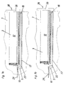
- Figs. 3a, 3b and 3c is an inventive arrangement in touch-latch design shown. It can be seen in Fig. 3a and in detail in Fig. 3b, that in such a Variant also in the closed end position of the movable furniture part 3, a gap 30th between the front of the inventive arrangement and the front panel 26 of the movable furniture part 3 is provided. This allows the opening of the movable Furniture part 3 on a known in such embodiments prior art analogous way, so it will not be discussed further here.
- a support by the drive unit 5 only after release of the movable furniture part 3, i. for example, in the in Fig. 3c shown state. This corresponds to the basic idea that the user to notice as little as possible of the support provided by the drive unit. It But also an immediate support, at least in the pressing on the Be provided front panel subsequent pull-out.
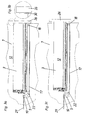
- FIG. 4 a shows a further exemplary embodiment of an arrangement according to the invention, wherein the actuator 11 of an initialization device included in the drive unit 6 can be seen.
- Fig. 4b can be seen in detail that in the closed end position the movable furniture part 3, a distance between the back of the movable furniture part 3 and the actuating element 11 is provided, so that the actuation of the actuating element 11 is carried out without contact by the movable furniture part 3. This is for example in an executed as an inductive sensor actuator 11 possible.
- Fig. 4c shows the movable furniture part 3 of FIGS. 4a and 4b in the tripped state.
- Fig. 5a shows a perspective view of one of the two for lateral mounting on the Inside a device according to the invention provided frame 14, wherein the two arranged on the frame rollers 18, the corresponding teeth for the over the rollers 18 have running toothed belt 17, can be seen.
- Fig. 5b shows in detail the Drive unit 5 with the drive unit controller 10, which in this embodiment via the partially integrated into the drive unit 5 gear 22 one of the rollers 18 and thus the toothed belt 17 drives.
- the movable was Furniture part 3 is not shown.
- Fig. 6 shows a further embodiment in which both side frames 14, 15 can be seen, wherein the drive unit 5 and that of this included gear 22 in the area between the frames on the rear wall, not shown the inventive arrangement is attached. For reasons of clarity was the attached to the frames 14, 15 movable furniture part 3 is not shown.
- FIGS. 7a and 7b now show an exemplary embodiment in which the connecting shaft 19 closes can be seen about the drive unit 5 with the rollers 18 of the two frames 15 in Connection stands.
- Fig. 7b can be seen in detail that the exercise of force in this Embodiment via an intermediate gear 22 takes place.
- Fig. 8a shows the arrangement of Figs. 7a and 7b in a different angle, so that the connection for power application of the drive unit 5 via the connecting shaft 19 a roller 18 of the drive unit 5 further away from the frame 15 can be seen.
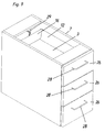
- Fig. 9 shows the perspective view of an embodiment of the invention Arrangement 7, the three movable furniture parts 3 with front panels 26 and handle elements 28th having. To recognize is partially the uppermost mounted movable furniture part 3, of which in particular, a side wall 12 and the rear wall 16. Sectionally recognizes one a part of the conductive connection 29.
- FIG. 10 shows analogous to FIG. 9 shows a variant of the arrangement according to the invention, in which a Touch-latch release is provided. Accordingly, no handle elements to the Front panels 26 are provided.
- Fig. 11a shows again the inventive arrangement of Fig. 10, wherein the uppermost stored movable furniture part 3 was brought into the open end position. It can be seen on the inside of the arrangement 7 according to the invention mounted on the side wall Frame 14, which consists of two parts and whose upper part is designed to be movable, while the lower part is attached to a side wall of the arrangement 7 according to the invention is.
- the detailed view 11b shows the drive unit 5 with the drive unit controller 10 as well the gear 22, the roller 18, the toothed belt 17 and a part of the power supply 29th
- Fig. 12a shows a prior art rotatably mounted disc 23 from Conductive material that is part of a magnetic encoder, not shown, wherein the disc 23 rotatable about a shaft, not shown, with the drive unit. 5 connected is.
- Inductive sensors 27 which can be seen directly above one of the two surfaces of the disc 23 are arranged.
- Two-channel decoder can span the width of each pulse between the two channels the rotational speed and the phase of the individual pulses, the direction of rotation of the Disk 23 and thus the associated with her drive unit 5 are determined and so be deduced to the linear movement of the movable furniture part 3.
- this registers the control device 1 by the of the position measuring device 4, of the the disk 23 and the sensors 27 in this embodiment represent a part, outgoing electrical signals and gives the drive unit 5 via a intermediate drive unit controller 10 command to accelerate the movable furniture part 3 in the direction intended by the user.
- Fig. 12b shows a perspective view of the two components 23 and 27 of FIG. 12a.
- FIG. 12d shows Elements of a position measuring device 4 of a further embodiment, which in present case is designed as an optical encoder and here, of course, at the same time Acceleration measuring device 2 represents.
- a position measuring device 4 of a further embodiment which in present case is designed as an optical encoder and here, of course, at the same time Acceleration measuring device 2 represents.
- Evident are light-emitting elements 25, whose light falls over a shutter 31 on light detecting elements 24, if not is interrupted by the intermediate rotating disk 23.
- the details can be found in the relevant specialist literature.
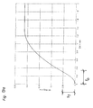
- FIGS. 13a, 13b and 13c show, with the aid of travel-time diagrams, a typical actuation process in the course of which the movable furniture part 3 moves from its closed end position into an intermediate position in which it temporarily comes to rest and after renewed actuation the user is moved to the open end position or, alternatively, back to the closed end position.
- a total path S of approximately 0.43 m between the closed and the open end position.
- the closed end position corresponds to the ordinate origin zero in the path-time diagrams.
- the closed end position corresponds to a position of the movable furniture part 3, in which a gap 30 remains between its front panel 31 and the front side of the arrangement according to the invention.
- FIG. 13b shows a possible course in which the user after a certain time again train on the located in the intermediate position movable furniture part 3 exerts, whereby the control unit 1 via the drive unit controller 10 of the drive unit 5 the command for uniform acceleration of the movable furniture part 3 in Direction of the train acceleration granted. It can therefore be seen in Fig.
- the partial path S 3 is a factory-set braking distance, which ensures a safe deceleration of the movable furniture part 3 during the transition to the open end position.
- this presents itself as a friction effect which is amplified in the area S 3.
- FIG. 13 c shows a likewise possible progression shape in which the user accelerates the movable furniture part 3 located in an intermediate position in the direction of the closed end position by pressure.
- the immediate onset supporting effect of the drive unit 5 which is reflected in the uniformly accelerated movement of the movable furniture part 3 over the section S 2 in the path-time diagram.
- a closed end position upstream protection path S 3 in which the drive unit 5 causes a uniformly accelerated deceleration movement of the movable furniture part 3, in order to transfer them safely and without unnecessary noise in the closed end position.
- the partial paths S 1 , S 2 , S 3 of the entire path S between the closed and the open end positions shown in FIGS. 13 a, 13 b, 13 c are usually preset at the factory. This corresponds to the idea that the user does not want to be burdened with technical details.
- a technically more dedicated user sets the partial routes S 1 , S 2 , S 3 or the time interval t o , via which an acceleration takes place, within certain limits (ie taking into account safety aspects).
- Fig. 14 was shown schematically, in which way the individual components of inventive arrangement exchange information with each other.
- the control device 1, a drive unit controller 10 and a Istwertbeticss worn 8 includes.
- the position measuring device 4 can signals the actual value calculation device 8 pass and has even the possibility of signals from receive the initialization device 6, which in turn via actuators 20, 11, 9 is triggered.
- the drive unit controller 10 receives signals from the Acceleration measuring device 2 and the actual value calculating device 8.
- the schematic logical representation of the information flow between the system elements does not necessarily correspond to the physical arrangement of the same. For example All system elements can save space in an integrated design physically arranged in the arrangement 7 according to the invention.
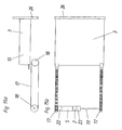
- FIGS. 15a and 15b show a schematic side view and top view, respectively the bottom surface of the movable furniture part 3 a conceivable arrangement of the system units shown.
- a side surface 13 of the movable Furniture part 3 with a front panel 26, in this embodiment, the inventive Arrangement 7 is designed as a touch-latch construction.
- the movable furniture part 3 is in connection with a belt 17, the two rollers 18 in turn in Connection with a drive unit 5 is.
- the power transmission takes place in this Embodiment on both sides by means of a connecting shaft 19.
- the power transmission of the drive unit 5 takes place in this embodiment via two gear 22, which are arranged on the left and right of the drive unit, and in conjunction with the Connecting shaft 19 are.
- Acceleration measuring device 2 between a transmission 22 and the drive unit 5 is arranged.
- the remaining system components such as the position measuring device 4, the actual value calculation device 8, the drive unit controller 10 and the Initialization device 6 and its possible actuators were in Figs. 15a and 15b are not shown. They can be explained as above in a the average Professional familiar manner be integrated in the illustrated system components and so on perform their functions.
Landscapes
- Power-Operated Mechanisms For Wings (AREA)
- Drawers Of Furniture (AREA)
Priority Applications (2)
| Application Number | Priority Date | Filing Date | Title |
|---|---|---|---|
| EP08011767.4A EP1992253B1 (fr) | 2002-06-27 | 2003-05-23 | Poussée auxiliaire |
| EP07015936.3A EP1849377B1 (fr) | 2002-06-27 | 2003-05-23 | Poussée auxiliaire |
Applications Claiming Priority (2)
| Application Number | Priority Date | Filing Date | Title |
|---|---|---|---|
| AT9622002 | 2002-06-27 | ||
| AT0096202A AT500362B1 (de) | 2002-06-27 | 2002-06-27 | Anordnung mit einem bewegbaren möbelteil und mit einer antriebseinheit |
Related Child Applications (4)
| Application Number | Title | Priority Date | Filing Date |
|---|---|---|---|
| EP07015936.3A Division EP1849377B1 (fr) | 2002-06-27 | 2003-05-23 | Poussée auxiliaire |
| EP08011767.4A Division EP1992253B1 (fr) | 2002-06-27 | 2003-05-23 | Poussée auxiliaire |
| EP07015936.3 Division-Into | 2007-08-14 | ||
| EP08011767.4 Division-Into | 2008-06-30 |
Publications (2)
| Publication Number | Publication Date |
|---|---|
| EP1374732A1 true EP1374732A1 (fr) | 2004-01-02 |
| EP1374732B1 EP1374732B1 (fr) | 2013-04-03 |
Family
ID=29716474
Family Applications (3)
| Application Number | Title | Priority Date | Filing Date |
|---|---|---|---|
| EP07015936.3A Expired - Lifetime EP1849377B1 (fr) | 2002-06-27 | 2003-05-23 | Poussée auxiliaire |
| EP08011767.4A Expired - Lifetime EP1992253B1 (fr) | 2002-06-27 | 2003-05-23 | Poussée auxiliaire |
| EP03011678A Expired - Lifetime EP1374732B1 (fr) | 2002-06-27 | 2003-05-23 | Poussée auxiliaire |
Family Applications Before (2)
| Application Number | Title | Priority Date | Filing Date |
|---|---|---|---|
| EP07015936.3A Expired - Lifetime EP1849377B1 (fr) | 2002-06-27 | 2003-05-23 | Poussée auxiliaire |
| EP08011767.4A Expired - Lifetime EP1992253B1 (fr) | 2002-06-27 | 2003-05-23 | Poussée auxiliaire |
Country Status (5)
| Country | Link |
|---|---|
| US (1) | US7602135B2 (fr) |
| EP (3) | EP1849377B1 (fr) |
| JP (1) | JP5009485B2 (fr) |
| CN (1) | CN1265749C (fr) |
| AT (1) | AT500362B1 (fr) |
Cited By (41)
| Publication number | Priority date | Publication date | Assignee | Title |
|---|---|---|---|---|
| AT413472B (de) * | 2004-08-16 | 2006-03-15 | Blum Gmbh Julius | Ausstossvorrichtung für ein bewegbares möbelteil |
| DE102004045568A1 (de) * | 2004-09-17 | 2006-03-30 | Küster Automotive Door Systems GmbH | Steuer- und/oder Regelvorrichtung für eine elektromotorisch betätigbare Verstelleinrichtung zum Verstellen, vorzugsweise zum translatorischen Verschieben, wenigstens eines Möbelteils |
| DE102005049488B3 (de) * | 2005-10-13 | 2006-11-09 | Küster Automotive Door Systems GmbH | Vorrichtung und Verfahren zum Verschließen oder zum Öffnen und Schließen von wenigstens einer Schublade, Klappe, Tür oder dergleichen |
| WO2007006061A1 (fr) * | 2005-07-12 | 2007-01-18 | Julius Blum Gmbh | Meuble |
| WO2007009133A1 (fr) * | 2005-07-20 | 2007-01-25 | Julius Blum Gmbh | Systeme d'entrainement pour une partie de meuble mobile |
| AT503032B1 (de) * | 2006-02-09 | 2007-07-15 | Blum Gmbh Julius | Schubladenantrieb |
| AT503034B1 (de) * | 2006-02-15 | 2007-07-15 | Blum Gmbh Julius | Anordnung mit wenigstens zwei angetriebenen möbelteilen |
| DE202006004718U1 (de) * | 2006-03-22 | 2007-08-02 | Grass Gmbh | Vorrichtung für die Bewegungsbeeinflussung von zueinander bewegbaren Möbelteilen und Möbel |
| DE202006005578U1 (de) * | 2006-04-04 | 2007-08-16 | Grass Gmbh | Vorrichtung zum Bewegen eines ersten Möbelteils relativ zu einem zweiten Möbelteil sowie Möbel |
| DE202006005579U1 (de) * | 2006-04-04 | 2007-08-16 | Grass Gmbh | Vorrichtung für die Bewegungsbeeinflussung von zueinander bewegbaren Möbelteilen und Möbel |
| DE202006006187U1 (de) * | 2006-04-18 | 2007-08-30 | Paul Hettich Gmbh & Co. Kg | Möbel |
| WO2007115773A1 (fr) * | 2006-04-04 | 2007-10-18 | Küster Automotive Door Systems GmbH | Meuble comprenant au moins un deuxième élément de meuble à déplacement motorisé par rapport à un premier élément meuble |
| WO2007147180A3 (fr) * | 2006-06-22 | 2008-02-14 | Blum Gmbh Julius | Dispostif de rétraction d'un tiroir |
| EP1710380A4 (fr) * | 2004-01-30 | 2008-03-26 | Thk Co Ltd | Dispositif d entra nement d un corps mobile et dispositif automatique de traction |
| WO2007115758A3 (fr) * | 2006-04-04 | 2008-04-17 | Grass Gmbh | Dispositif de déplacement d'un premier élément de meuble par rapport à un deuxième élément de meuble |
| WO2007115753A3 (fr) * | 2006-04-04 | 2008-04-24 | Grass Gmbh | Dispositif pour influencer le déplacement de plusieurs éléments de meubles mobiles, procédé de configuration d'un tel dispositif et meuble |
| DE102006038558A1 (de) * | 2006-08-17 | 2008-04-30 | Vibradorm Gmbh | Anordnung zur Steuerung des Antriebs eines elektrisch verstellbaren Möbels |
| EP1790252A3 (fr) * | 2005-11-24 | 2008-05-28 | Küster Automotive Door Systems GmbH | Système de commande pour l'ouverture de tiroirs sans poignée, en appuyant sur la face frontale sans que la course d'actionnement ne soit augmentée |
| DE202007001646U1 (de) | 2007-01-31 | 2008-06-12 | Deon Ag | Elektromotorischer Möbelantrieb |
| DE202007001647U1 (de) | 2007-01-31 | 2008-07-03 | Linrot Holding Ag | Möbel |
| DE202007004338U1 (de) | 2007-03-21 | 2008-08-07 | Linrot Holding Ag | Möbel |
| WO2007115755A3 (fr) * | 2006-04-04 | 2008-08-21 | Grass Gmbh | Procédé pour régler un espace de fermeture dans un meuble, et dispositif pour mettre en mouvement une pièce de meuble mobile par rapport à une pièce de meuble fixe, et meuble correspondant |
| DE212007000021U1 (de) | 2006-02-15 | 2008-08-21 | Julius Blum Gmbh | Möbel mit einem angetriebenen Möbelteil |
| DE202007001580U1 (de) | 2007-01-30 | 2008-09-11 | Deon Ag | Möbel |
| DE202007001582U1 (de) | 2007-01-30 | 2008-09-11 | Deon Ag | Möbel |
| WO2008031748A3 (fr) * | 2006-09-15 | 2009-01-29 | Hettich Paul Gmbh & Co Kg | Dispositif détecteur d'un dispositif de déploiement pour parties de meubles |
| WO2008098266A3 (fr) * | 2007-02-15 | 2009-05-07 | Blum Gmbh Julius | Éjecteur pour une partie de meuble mobile |
| WO2009108970A1 (fr) * | 2008-03-07 | 2009-09-11 | Julius Blum Gmbh | Mécanisme d'entraînement pour meuble, avec une unité d'entraînement |
| WO2009114885A1 (fr) * | 2008-03-17 | 2009-09-24 | Julius Blum Gmbh | Agencement de réglage avec deux dispositifs de réglage |
| DE102009012017A1 (de) * | 2009-03-06 | 2010-09-09 | Paul Hettich Gmbh & Co. Kg | Verfahren zum Ausrichten der Frontblende eines Schubkastens an einem Möbel, Ausrichtungssystem und Verstelleinrichtung |
| RU2401034C2 (ru) * | 2005-07-20 | 2010-10-10 | Юлиус Блум Гмбх | Привод для подвижной части мебели |
| US8005577B2 (en) | 2006-04-04 | 2011-08-23 | Grass Gmbh | Apparatus for controlling the movement of furniture parts which can be moved with respect to one another, and piece of furniture |
| US8026686B2 (en) | 2006-04-04 | 2011-09-27 | Grass Gmbh | Device for controlling the movement of a plurality of movable furniture parts and method for configuration of a device such as this, and piece of furniture |
| DE102010012660A1 (de) | 2010-03-24 | 2011-09-29 | Linrot Holding Ag | Möbel |
| US20110241509A1 (en) * | 2008-12-15 | 2011-10-06 | Grass Gmbh | Apparatus for driving an actuating mechanism, opening apparatus, and piece of furniture |
| US8246128B2 (en) | 2009-01-16 | 2012-08-21 | Julius Blum Gmbh | Trigger sensor for a furniture drive |
| AT505562B1 (de) * | 2007-07-24 | 2013-04-15 | Blum Gmbh Julius | Möbelantrieb |
| CN103228180A (zh) * | 2010-11-23 | 2013-07-31 | 尤利乌斯·布卢姆有限公司 | 用于将功能件安装在抽屉拉出引导装置的导轨上的装置 |
| RU2539344C2 (ru) * | 2009-05-09 | 2015-01-20 | Хеттих Холдинг Гмбх Унд Ко. Охг | Предмет мебели с гибким экраном |
| EP2283294A4 (fr) * | 2008-03-26 | 2015-06-03 | Lg Electronics Inc | Refrigerateur, systeme et procede servant a commander un tiroir de refrigerateur |
| AT526799A1 (de) * | 2022-12-23 | 2024-07-15 | Blum Gmbh Julius | Recheneinheitgestütztes Verfahren zur Bewegung eines bewegbaren Möbelteiles |
Families Citing this family (47)
| Publication number | Priority date | Publication date | Assignee | Title |
|---|---|---|---|---|
| AT502574B1 (de) * | 2003-05-19 | 2007-08-15 | Blum Gmbh Julius | Möbel mit einem bewegbaren möbelteil |
| AT500722B1 (de) * | 2004-08-16 | 2009-06-15 | Blum Gmbh Julius | Trägerelement zur befestigung in einem möbelkorpus |
| WO2006112189A1 (fr) * | 2005-03-31 | 2006-10-26 | Cleanup Corporation | Unite d'entrainement d'un corps mobile et dispositif de tiroir automatique utilisant celle-ci |
| DE202006020236U1 (de) * | 2005-11-10 | 2008-02-07 | Grass Gmbh | Vorrichtung zum Öffnen und Schließen eines bewegbaren Möbelteils und Möbelteil |
| AT503248B1 (de) * | 2006-03-03 | 2011-07-15 | Blum Gmbh Julius | Anordnung mit elektrischen antriebseinheiten für schubladen |
| AT503497B1 (de) * | 2006-04-05 | 2012-05-15 | Blum Gmbh Julius | Antriebsmechanismus für ein in oder an einem möbel bewegbar gelagertes möbelteil |
| AT504375B1 (de) * | 2006-10-23 | 2010-01-15 | Blum Gmbh Julius | Möbel mit einer antriebsvorrichtung für bewegbare möbelteile |
| DE202007004337U1 (de) * | 2007-03-21 | 2008-09-04 | Linrot Holding Ag | Elektromotorischer Möbelantrieb |
| AT505207B1 (de) * | 2007-04-23 | 2011-08-15 | Blum Gmbh Julius | Einzugsvorrichtung für ein bewegbares möbelteil |
| AT10097U1 (de) * | 2007-04-30 | 2008-09-15 | Blum Gmbh Julius | Federpuffer für ein möbel |
| DE202007006301U1 (de) * | 2007-04-30 | 2008-03-20 | Grass Gmbh | Möbel und Vorrichtung zum Ausstoßen eines Möbelteils, das an einem feststehenden Möbelteil bewegbar aufgenommen ist |
| DE202007006298U1 (de) * | 2007-04-30 | 2008-06-05 | Grass Gmbh | Möbel und Vorrichtung zum Ausstoßen eines Möbelteils, das an einem feststehenden Möbelteil bewegbar aufgenommen ist |
| AT505209B1 (de) * | 2007-05-07 | 2012-04-15 | Blum Gmbh Julius | Antrieb für ein bewegbares möbelteil |
| AT506251B1 (de) | 2007-12-20 | 2012-12-15 | Blum Gmbh Julius | Möbelantrieb |
| DE102008007377A1 (de) * | 2008-02-01 | 2009-08-06 | Paul Hettich Gmbh & Co. Kg | Ausstoßvorrichtung und Verfahren zur Betätigung eines Ausstoßhebels |
| CN101981396A (zh) * | 2008-03-26 | 2011-02-23 | Lg电子株式会社 | 用于驱动冰箱抽屉的系统和方法 |
| EP2283290A4 (fr) * | 2008-03-26 | 2014-01-15 | Lg Electronics Inc | Refrigerateur |
| EP3553434B1 (fr) * | 2008-03-26 | 2021-07-28 | Lg Electronics Inc. | Procédé de commande d'un tiroir dans un réfrigérateur |
| KR101441133B1 (ko) * | 2008-03-26 | 2014-09-17 | 엘지전자 주식회사 | 냉장고의 드로어 구동 제어 방법 |
| US8217613B2 (en) * | 2008-03-26 | 2012-07-10 | Lg Electronics Inc. | System and method for driving a drawer of a refrigerator and refrigerator employing same |
| KR101380557B1 (ko) * | 2008-03-26 | 2014-04-01 | 엘지전자 주식회사 | 냉장고의 드로어 구동 시스템 및 제어 방법 |
| AT10668U1 (de) * | 2008-08-29 | 2009-08-15 | Blum Gmbh Julius | Gehäuse zur wenigstens teilweisen aufnahme eines möbelbeschlages |
| KR101592573B1 (ko) * | 2009-03-20 | 2016-02-05 | 엘지전자 주식회사 | 냉장고 |
| KR101592572B1 (ko) * | 2009-03-20 | 2016-02-05 | 엘지전자 주식회사 | 냉장고 및 그 제어 방법 |
| KR101592574B1 (ko) * | 2009-03-20 | 2016-02-05 | 엘지전자 주식회사 | 냉장고 및 그 제어 방법 |
| KR101592575B1 (ko) * | 2009-03-20 | 2016-02-05 | 엘지전자 주식회사 | 냉장고 |
| KR101592571B1 (ko) * | 2009-03-20 | 2016-02-05 | 엘지전자 주식회사 | 냉장고 및 그 제어 방법 |
| DE102009015690A1 (de) * | 2009-03-31 | 2010-10-07 | Logicdata Electronic & Software Entwicklungs Gmbh | Linearantrieb und Tisch mit Linearantrieb |
| US9217601B2 (en) | 2009-12-22 | 2015-12-22 | Lg Electronics Inc. | Refrigerator with a convertible compartment |
| DE202010009274U1 (de) * | 2010-06-18 | 2011-11-02 | Grass Gmbh | Vorrichtung zum Öffnen eines Möbels sowie Möbel mit einer Vorrichtung |
| US8851300B2 (en) * | 2010-12-13 | 2014-10-07 | Proper Storage Systems, LLC | Roll-out shelving storage rack system |
| KR101057431B1 (ko) | 2011-04-06 | 2011-08-19 | 김형운 | 강도퇴치장치 |
| DE102011007540A1 (de) * | 2011-04-15 | 2012-10-18 | Kesseböhmer Produktions GmbH & Co. KG | Kalbrierbare Teleskopsäule, Möbel mit kalibrierbarer Teleskopsäule, sowie Verfahren zur Kalibrierung einer Teleskopsäule |
| US8983653B2 (en) * | 2011-07-15 | 2015-03-17 | Advantage Pharmacy Services Llc | Electromechanical latch and ejector |
| US9790025B2 (en) | 2012-03-09 | 2017-10-17 | Simplehuman, Llc | Trash can with clutch mechanism |
| DE102012110959A1 (de) * | 2012-11-14 | 2014-05-28 | Logicdata Electronic & Software Entwicklungs Gmbh | Bedienteil für ein Möbelsteuerungssystem, Möbelsteuerungssystem und elektrisch verstellbares Möbel |
| US9504323B1 (en) * | 2012-12-20 | 2016-11-29 | Fedele Anthony PORRECA | Drawer slide structure |
| US20160047160A1 (en) * | 2013-02-27 | 2016-02-18 | Nam Duc HUYNH | Enclosure access apparatus and method |
| US9089047B2 (en) * | 2013-09-20 | 2015-07-21 | International Business Machines Corporation | Grounded belt and movable drawer apparatus |
| CN104003048B (zh) * | 2014-05-20 | 2016-08-24 | 无锡瑞巴斯医疗器械有限公司 | 一种移动药箱 |
| CN105395334A (zh) * | 2015-12-12 | 2016-03-16 | 南阳医学高等专科学校 | 一种便携式外科护理托板 |
| US10392854B2 (en) * | 2016-02-11 | 2019-08-27 | Technology Construction, Inc. | Systems and methods for an automatic sliding door having a slide and rail assembly |
| CN105919309A (zh) * | 2016-05-16 | 2016-09-07 | 苏州通快净化科技有限公司 | 一种智能抽屉柜 |
| WO2019151820A1 (fr) * | 2018-02-05 | 2019-08-08 | Samsung Electronics Co., Ltd. | Réfrigérateur |
| JP7157564B2 (ja) * | 2018-06-11 | 2022-10-20 | 株式会社Fuji | 対基板作業機 |
| EP4251542A4 (fr) * | 2020-11-25 | 2024-11-06 | Simplehuman LLC | Récipients à déchets intégrés pouvant être actionnés électroniquement |
| AT526504B1 (de) * | 2022-12-23 | 2024-04-15 | Blum Gmbh Julius | Anordnung umfassend ein feststehendes Möbelteil, ein bewegbares Möbelteil und eine Führungsvorrichtung |
Citations (6)
| Publication number | Priority date | Publication date | Assignee | Title |
|---|---|---|---|---|
| DE1017351B (de) | 1956-03-16 | 1957-10-10 | Dr Otto A Becker | Einrichtung fuer das Ausziehen und Einschieben von in einem Schreibtisch od. dgl. angeordneten Schubladen, Schubkaesten, Zuegen od. dgl. |
| US5158347A (en) | 1990-02-21 | 1992-10-27 | Meridian Incorporated | Subcabinet movement initiator |
| EP0957225A1 (fr) | 1998-05-11 | 1999-11-17 | bulthaup GmbH & Co. Küchensysteme | Dispositif pour l'ouverture d'un élément de fermeture |
| DE10105756A1 (de) * | 2000-02-14 | 2001-08-16 | Fulterer Gmbh Lustenau | Steuerungsverfahren |
| EP1323363A1 (fr) * | 2001-12-27 | 2003-07-02 | Julius Blum Gesellschaft m.b.H. | Dispositif avec une pièce de meuble mobile, un dispositif d'entraínement et un dispositif de réglage |
| EP1323364A1 (fr) * | 2001-12-27 | 2003-07-02 | Julius Blum Gesellschaft m.b.H. | Element de meuble mobile |
Family Cites Families (20)
| Publication number | Priority date | Publication date | Assignee | Title |
|---|---|---|---|---|
| US3298765A (en) * | 1965-08-18 | 1967-01-17 | Rakich George | Cash drawers and method for operating same |
| US3794401A (en) * | 1971-10-20 | 1974-02-26 | Wright Barry Corp | Door guide |
| US4159658A (en) * | 1977-04-04 | 1979-07-03 | Bridgeport Machines Division Of Textron Inc. | Rotary index tables |
| JPS55166763A (en) * | 1979-06-12 | 1980-12-26 | Tokyo Electric Co Ltd | Electronic cash register |
| DE3504013A1 (de) * | 1985-02-06 | 1986-08-07 | Jagenberg AG, 4000 Düsseldorf | Positioniereinrichtung fuer mehrere, nebeneinander und auf gegenseitigen abstand verfahrbare einheiten |
| JPH07120216B2 (ja) * | 1988-10-21 | 1995-12-20 | 新技術事業団 | 位置制御方法 |
| ATE114846T1 (de) * | 1989-01-19 | 1994-12-15 | Mib Elettronica | Vorrichtung zum schützen und verarbeiten von banknoten und wertgegenstände. |
| JP2814100B2 (ja) | 1989-04-06 | 1998-10-22 | 新関西ベアリング株式会社 | 昇降装置 |
| JP2813909B2 (ja) * | 1989-12-28 | 1998-10-22 | 東芝機械株式会社 | 数値制御装置のバックラッシュ補正方式 |
| JPH03287344A (ja) * | 1990-04-02 | 1991-12-18 | Howa Mach Ltd | 割出し装置 |
| US5392951A (en) * | 1993-05-20 | 1995-02-28 | Lionville Systems, Inc. | Drawer operating system |
| DE4402899C1 (de) * | 1994-02-02 | 1995-08-17 | Dorma Gmbh & Co Kg | Betriebsverfahren für den Betrieb einer Karusselltür |
| US5716114A (en) | 1996-06-07 | 1998-02-10 | Pyxis Corporation | Jerk-resistant drawer operating system |
| US5635808A (en) * | 1995-08-30 | 1997-06-03 | Utica Enterprises, Inc. | Method and system for controlling the motion of a rotary drive of a rotary index table assembly |
| JPH0995140A (ja) * | 1995-10-02 | 1997-04-08 | Oi Seisakusho Co Ltd | 車両用電動対象物の駆動制御装置 |
| JP3340622B2 (ja) * | 1996-06-07 | 2002-11-05 | 本田技研工業株式会社 | 電動パワースライドドア装置 |
| JP3241268B2 (ja) * | 1996-06-12 | 2001-12-25 | 本田技研工業株式会社 | 電動パワースライドドア装置 |
| JPH1189642A (ja) | 1997-09-18 | 1999-04-06 | Matsushita Electric Ind Co Ltd | 操作力軽減装置 |
| EP0994560A1 (fr) | 1998-10-16 | 2000-04-19 | Klaus Appel | Méthode et dispositif d'ajustement synchrone des organes mobiles, particulièrement des pieds de table |
| US6137255A (en) * | 1999-07-30 | 2000-10-24 | Otis Elevator Company | Apparatus and method of controlling a linear motor door operator |
-
2002
- 2002-06-27 AT AT0096202A patent/AT500362B1/de not_active IP Right Cessation
-
2003
- 2003-05-23 EP EP07015936.3A patent/EP1849377B1/fr not_active Expired - Lifetime
- 2003-05-23 EP EP08011767.4A patent/EP1992253B1/fr not_active Expired - Lifetime
- 2003-05-23 EP EP03011678A patent/EP1374732B1/fr not_active Expired - Lifetime
- 2003-05-29 US US10/447,142 patent/US7602135B2/en not_active Expired - Fee Related
- 2003-06-19 JP JP2003174804A patent/JP5009485B2/ja not_active Expired - Fee Related
- 2003-06-26 CN CNB031493122A patent/CN1265749C/zh not_active Expired - Fee Related
Patent Citations (6)
| Publication number | Priority date | Publication date | Assignee | Title |
|---|---|---|---|---|
| DE1017351B (de) | 1956-03-16 | 1957-10-10 | Dr Otto A Becker | Einrichtung fuer das Ausziehen und Einschieben von in einem Schreibtisch od. dgl. angeordneten Schubladen, Schubkaesten, Zuegen od. dgl. |
| US5158347A (en) | 1990-02-21 | 1992-10-27 | Meridian Incorporated | Subcabinet movement initiator |
| EP0957225A1 (fr) | 1998-05-11 | 1999-11-17 | bulthaup GmbH & Co. Küchensysteme | Dispositif pour l'ouverture d'un élément de fermeture |
| DE10105756A1 (de) * | 2000-02-14 | 2001-08-16 | Fulterer Gmbh Lustenau | Steuerungsverfahren |
| EP1323363A1 (fr) * | 2001-12-27 | 2003-07-02 | Julius Blum Gesellschaft m.b.H. | Dispositif avec une pièce de meuble mobile, un dispositif d'entraínement et un dispositif de réglage |
| EP1323364A1 (fr) * | 2001-12-27 | 2003-07-02 | Julius Blum Gesellschaft m.b.H. | Element de meuble mobile |
Cited By (81)
| Publication number | Priority date | Publication date | Assignee | Title |
|---|---|---|---|---|
| EP1710380A4 (fr) * | 2004-01-30 | 2008-03-26 | Thk Co Ltd | Dispositif d entra nement d un corps mobile et dispositif automatique de traction |
| US8894163B2 (en) | 2004-08-16 | 2014-11-25 | Julius Blum Gmbh | Ejection device for a displaceable furniture component |
| EP2298130A1 (fr) | 2004-08-16 | 2011-03-23 | Julius Blum Gmbh | Poussoir pour un élément de meuble mobile |
| AT413472B (de) * | 2004-08-16 | 2006-03-15 | Blum Gmbh Julius | Ausstossvorrichtung für ein bewegbares möbelteil |
| US8360537B2 (en) | 2004-08-16 | 2013-01-29 | Julius Blum Gmbh | Ejection device for a displaceable furniture component |
| US8029078B2 (en) | 2004-08-16 | 2011-10-04 | Julium Blum GmbH | Ejection device for a movable furniture component |
| EP2305068A1 (fr) | 2004-08-16 | 2011-04-06 | Julius Blum Gmbh | Poussoir pour un élément de meuble mobile |
| EP2308347A1 (fr) | 2004-08-16 | 2011-04-13 | Julius Blum Gmbh | Poussoir pour un élément de meuble mobile |
| DE102004045568B4 (de) * | 2004-09-17 | 2016-11-03 | Grass Gmbh | Steuer- und/oder Regelvorrichtung für eine elektromotorisch betätigbare Verstelleinrichtung zum Verstellen, vorzugsweise zum translatorischen Verschieben, wenigstens eines Möbelteils |
| DE102004045568A1 (de) * | 2004-09-17 | 2006-03-30 | Küster Automotive Door Systems GmbH | Steuer- und/oder Regelvorrichtung für eine elektromotorisch betätigbare Verstelleinrichtung zum Verstellen, vorzugsweise zum translatorischen Verschieben, wenigstens eines Möbelteils |
| EP1637943B2 (fr) † | 2004-09-17 | 2012-03-07 | Küster Automotive Door Systems GmbH | Dispositif de commande et/ou de régulation pour un positionneur électromécanique, en particulier, pour translater un élément de mobilier |
| CN101208027B (zh) * | 2005-07-12 | 2010-08-18 | 尤利乌斯·布卢姆有限公司 | 家具 |
| WO2007006061A1 (fr) * | 2005-07-12 | 2007-01-18 | Julius Blum Gmbh | Meuble |
| US7645002B2 (en) | 2005-07-12 | 2010-01-12 | Julius Blum Gmbh | Article of furniture |
| RU2403844C2 (ru) * | 2005-07-20 | 2010-11-20 | Юлиус Блум Гмбх | Приводной механизм для подвижной части мебели |
| US7825617B2 (en) | 2005-07-20 | 2010-11-02 | Julius Blum Gmbh | Drive for a movable furniture part |
| RU2401034C2 (ru) * | 2005-07-20 | 2010-10-10 | Юлиус Блум Гмбх | Привод для подвижной части мебели |
| WO2007009133A1 (fr) * | 2005-07-20 | 2007-01-25 | Julius Blum Gmbh | Systeme d'entrainement pour une partie de meuble mobile |
| US8134313B2 (en) | 2005-10-13 | 2012-03-13 | Kuester Automotive Door Systems Gmbh | Device and method for closing, or opening and closing, at least one drawer, flap, door, or the like |
| WO2007042266A1 (fr) * | 2005-10-13 | 2007-04-19 | Küster Automotive Door Systems GmbH | Dispositif et procede pour fermer ou pour ouvrir et fermer au moins un tiroir, un abattant, une porte, ou analogue |
| CN101331292B (zh) * | 2005-10-13 | 2013-01-02 | 屈斯特自动门系统有限公司 | 用于关闭或者用于打开和关闭至少一个抽屉、盖、门等的装置和方法 |
| DE102005049488B3 (de) * | 2005-10-13 | 2006-11-09 | Küster Automotive Door Systems GmbH | Vorrichtung und Verfahren zum Verschließen oder zum Öffnen und Schließen von wenigstens einer Schublade, Klappe, Tür oder dergleichen |
| DE102005049488B8 (de) * | 2005-10-13 | 2007-02-15 | Grass Gmbh | Vorrichtung und Verfahren zum Verschließen oder zum Öffnen und Schließen von wenigstens einer Schublade, Klappe, Tür oder dergleichen |
| EP1790252A3 (fr) * | 2005-11-24 | 2008-05-28 | Küster Automotive Door Systems GmbH | Système de commande pour l'ouverture de tiroirs sans poignée, en appuyant sur la face frontale sans que la course d'actionnement ne soit augmentée |
| AT503032B1 (de) * | 2006-02-09 | 2007-07-15 | Blum Gmbh Julius | Schubladenantrieb |
| WO2007090211A1 (fr) * | 2006-02-09 | 2007-08-16 | Julius Blum Gmbh | Mécanisme d'entraînement pour tiroir |
| AT503034B1 (de) * | 2006-02-15 | 2007-07-15 | Blum Gmbh Julius | Anordnung mit wenigstens zwei angetriebenen möbelteilen |
| AT503192B1 (de) * | 2006-02-15 | 2012-01-15 | Blum Gmbh Julius | Möbel mit einem angetriebenen möbelteil |
| DE212007000021U1 (de) | 2006-02-15 | 2008-08-21 | Julius Blum Gmbh | Möbel mit einem angetriebenen Möbelteil |
| DE212006000083U1 (de) | 2006-02-15 | 2008-08-21 | Julius Blum Gmbh | Anordnung mit wenigstens zwei angetriebenen Möbelteilen |
| WO2007092969A1 (fr) * | 2006-02-15 | 2007-08-23 | Julius Blum Gmbh | Dispositif comprenant au moins deux parties de meuble entraînables |
| WO2007107355A3 (fr) * | 2006-03-22 | 2008-07-31 | Grass Gmbh | Dispositif destiné à influencer un mouvement d'éléments de meuble déplaçables les uns par rapport aux autres, et meuble correspondant |
| US7883162B2 (en) | 2006-03-22 | 2011-02-08 | Grass Gmbh | Device for influencing the movement of furniture parts which can be moved with respect to one another, and piece of furniture |
| DE202006004718U1 (de) * | 2006-03-22 | 2007-08-02 | Grass Gmbh | Vorrichtung für die Bewegungsbeeinflussung von zueinander bewegbaren Möbelteilen und Möbel |
| US8044627B2 (en) | 2006-04-04 | 2011-10-25 | Grass Gmbh | Device for controlling the movement of furniture parts which can be moved with respect to one another, and a piece of furniture |
| US8013558B2 (en) | 2006-04-04 | 2011-09-06 | Grass Gmbh | Method for adjusting a closing gap in a piece of furniture, device for moving a movable furniture part relative to a stationary furniture part, and piece of furniture |
| DE202006005578U1 (de) * | 2006-04-04 | 2007-08-16 | Grass Gmbh | Vorrichtung zum Bewegen eines ersten Möbelteils relativ zu einem zweiten Möbelteil sowie Möbel |
| DE202006005579U1 (de) * | 2006-04-04 | 2007-08-16 | Grass Gmbh | Vorrichtung für die Bewegungsbeeinflussung von zueinander bewegbaren Möbelteilen und Möbel |
| US7688015B2 (en) | 2006-04-04 | 2010-03-30 | Grass Gmbh | Device for moving a first furniture part relative to a second furniture part |
| WO2007115773A1 (fr) * | 2006-04-04 | 2007-10-18 | Küster Automotive Door Systems GmbH | Meuble comprenant au moins un deuxième élément de meuble à déplacement motorisé par rapport à un premier élément meuble |
| CN101448433B (zh) * | 2006-04-04 | 2012-07-04 | 格拉斯有限公司 | 用于影响多个可动家具部件的运动的装置、配置这种装置的方法以及家具 |
| WO2007115761A1 (fr) * | 2006-04-04 | 2007-10-18 | Grass Gmbh | Dispositif pour influencer le déplacement d'éléments de meuble mobiles et meuble |
| EP2407057A1 (fr) | 2006-04-04 | 2012-01-18 | Küster Automotive Door Systems GmbH | Meuble doté d'au moins deux éléments de meuble supplémentaires pouvant être déplacés de manière motorisée par rapport à au moins un premier élément de meuble |
| US7812561B2 (en) | 2006-04-04 | 2010-10-12 | Grass Gmbh | Device for controlling a movement of furniture parts which can be moved with respect to one another, and piece of furniture |
| US7816880B2 (en) | 2006-04-04 | 2010-10-19 | Grass Gmbh | Device for controlling the movement of a moveable furniture part, and a piece of furniture having a device such as this |
| WO2007115758A3 (fr) * | 2006-04-04 | 2008-04-17 | Grass Gmbh | Dispositif de déplacement d'un premier élément de meuble par rapport à un deuxième élément de meuble |
| WO2007115755A3 (fr) * | 2006-04-04 | 2008-08-21 | Grass Gmbh | Procédé pour régler un espace de fermeture dans un meuble, et dispositif pour mettre en mouvement une pièce de meuble mobile par rapport à une pièce de meuble fixe, et meuble correspondant |
| WO2007115753A3 (fr) * | 2006-04-04 | 2008-04-24 | Grass Gmbh | Dispositif pour influencer le déplacement de plusieurs éléments de meubles mobiles, procédé de configuration d'un tel dispositif et meuble |
| US8026685B2 (en) | 2006-04-04 | 2011-09-27 | Grass Gmbh | Device for controlling the movement of a plurality of moveable furniture parts, and a method for configuration of a device such as this, and piece of furniture |
| US8026686B2 (en) | 2006-04-04 | 2011-09-27 | Grass Gmbh | Device for controlling the movement of a plurality of movable furniture parts and method for configuration of a device such as this, and piece of furniture |
| WO2007115757A3 (fr) * | 2006-04-04 | 2008-05-29 | Grass Gmbh | Dispositif pour influencer le déplacement de plusieurs éléments de meubles mobiles et procédé de configuration d'un tel dispositif et meuble |
| US7994743B2 (en) | 2006-04-04 | 2011-08-09 | Grass Gmbh | Device for moving a first furniture part relative to a second furniture part, and a piece of furniture |
| US8005577B2 (en) | 2006-04-04 | 2011-08-23 | Grass Gmbh | Apparatus for controlling the movement of furniture parts which can be moved with respect to one another, and piece of furniture |
| DE202006006187U1 (de) * | 2006-04-18 | 2007-08-30 | Paul Hettich Gmbh & Co. Kg | Möbel |
| WO2007147180A3 (fr) * | 2006-06-22 | 2008-02-14 | Blum Gmbh Julius | Dispostif de rétraction d'un tiroir |
| US7780251B2 (en) | 2006-06-22 | 2010-08-24 | Julius Blum Gmbh | Retracting device for a drawer |
| DE102006038558A1 (de) * | 2006-08-17 | 2008-04-30 | Vibradorm Gmbh | Anordnung zur Steuerung des Antriebs eines elektrisch verstellbaren Möbels |
| WO2008031748A3 (fr) * | 2006-09-15 | 2009-01-29 | Hettich Paul Gmbh & Co Kg | Dispositif détecteur d'un dispositif de déploiement pour parties de meubles |
| DE202007001580U1 (de) | 2007-01-30 | 2008-09-11 | Deon Ag | Möbel |
| DE202007001582U1 (de) | 2007-01-30 | 2008-09-11 | Deon Ag | Möbel |
| DE202007001647U1 (de) | 2007-01-31 | 2008-07-03 | Linrot Holding Ag | Möbel |
| DE202007001646U1 (de) | 2007-01-31 | 2008-06-12 | Deon Ag | Elektromotorischer Möbelantrieb |
| WO2008098266A3 (fr) * | 2007-02-15 | 2009-05-07 | Blum Gmbh Julius | Éjecteur pour une partie de meuble mobile |
| DE202007004338U1 (de) | 2007-03-21 | 2008-08-07 | Linrot Holding Ag | Möbel |
| AT505562B1 (de) * | 2007-07-24 | 2013-04-15 | Blum Gmbh Julius | Möbelantrieb |
| US8324842B2 (en) | 2008-03-07 | 2012-12-04 | Julius Blum Gmbh | Furniture drive with a drive unit |
| WO2009108970A1 (fr) * | 2008-03-07 | 2009-09-11 | Julius Blum Gmbh | Mécanisme d'entraînement pour meuble, avec une unité d'entraînement |
| DE112009000548B4 (de) * | 2008-03-17 | 2017-03-16 | Julius Blum Gmbh | Stellanordnung mit zwei Stellvorrichtungen |
| WO2009114885A1 (fr) * | 2008-03-17 | 2009-09-24 | Julius Blum Gmbh | Agencement de réglage avec deux dispositifs de réglage |
| EP2283294A4 (fr) * | 2008-03-26 | 2015-06-03 | Lg Electronics Inc | Refrigerateur, systeme et procede servant a commander un tiroir de refrigerateur |
| US20110241509A1 (en) * | 2008-12-15 | 2011-10-06 | Grass Gmbh | Apparatus for driving an actuating mechanism, opening apparatus, and piece of furniture |
| AT507805B1 (de) * | 2009-01-16 | 2013-09-15 | Blum Gmbh Julius | Auslösesensor für einen möbelantrieb |
| US8246128B2 (en) | 2009-01-16 | 2012-08-21 | Julius Blum Gmbh | Trigger sensor for a furniture drive |
| DE102009012017A1 (de) * | 2009-03-06 | 2010-09-09 | Paul Hettich Gmbh & Co. Kg | Verfahren zum Ausrichten der Frontblende eines Schubkastens an einem Möbel, Ausrichtungssystem und Verstelleinrichtung |
| DE102009012017B4 (de) * | 2009-03-06 | 2020-02-13 | Paul Hettich Gmbh & Co. Kg | Verfahren zum Ausrichten der Frontblende eines Schubkastens an einem Möbel und Ausrichtungssystem |
| RU2539344C2 (ru) * | 2009-05-09 | 2015-01-20 | Хеттих Холдинг Гмбх Унд Ко. Охг | Предмет мебели с гибким экраном |
| DE102010012660A1 (de) | 2010-03-24 | 2011-09-29 | Linrot Holding Ag | Möbel |
| US8911038B2 (en) | 2010-11-23 | 2014-12-16 | Julius Blum Gmbh | Device for attaching a functional part to a rail of a drawer pull-out guide |
| CN103228180A (zh) * | 2010-11-23 | 2013-07-31 | 尤利乌斯·布卢姆有限公司 | 用于将功能件安装在抽屉拉出引导装置的导轨上的装置 |
| AT526799A1 (de) * | 2022-12-23 | 2024-07-15 | Blum Gmbh Julius | Recheneinheitgestütztes Verfahren zur Bewegung eines bewegbaren Möbelteiles |
| AT526799B1 (de) * | 2022-12-23 | 2024-11-15 | Blum Gmbh Julius | Recheneinheitgestütztes Verfahren zur Bewegung eines bewegbaren Möbelteiles |
Also Published As
| Publication number | Publication date |
|---|---|
| US20040100169A1 (en) | 2004-05-27 |
| EP1849377A3 (fr) | 2012-11-14 |
| US7602135B2 (en) | 2009-10-13 |
| CN1265749C (zh) | 2006-07-26 |
| JP5009485B2 (ja) | 2012-08-22 |
| EP1992253B1 (fr) | 2016-07-27 |
| JP2004024873A (ja) | 2004-01-29 |
| EP1849377B1 (fr) | 2013-04-17 |
| AT500362A1 (de) | 2005-12-15 |
| CN1468569A (zh) | 2004-01-21 |
| EP1849377A2 (fr) | 2007-10-31 |
| EP1374732B1 (fr) | 2013-04-03 |
| EP1992253A1 (fr) | 2008-11-19 |
| AT500362B1 (de) | 2007-01-15 |
Similar Documents
| Publication | Publication Date | Title |
|---|---|---|
| EP1992253B1 (fr) | Poussée auxiliaire | |
| AT413631B (de) | Anordnung mit einem bewegbaren möbelteil, mit einer antriebseinheit und mit einer regeleinrichtung | |
| EP1624772B1 (fr) | Procede pour entrainer une partie de meuble mobile | |
| EP1624773A1 (fr) | Meuble comportant une partie mobile | |
| EP2347077B1 (fr) | Agencement d'entrainement pour la commande motorisee d'un element de fermeture d'un vehicule automobile | |
| AT414004B (de) | Möbel | |
| DE19825353C2 (de) | Laderaumabdeckung für Kraftfahrzeuge, insbesondere für Kombinations-Personenkraftwagen od. dgl. | |
| DE19739543A1 (de) | Sicherheitseinrichtung für motorisch angetriebene Tore | |
| DE2640045C3 (de) | Vorrichtung zur automatischen Steuerung einer Tür zwischen ihrer geschlossenen und ihrer geöffneten Stellung | |
| DE2818461C2 (fr) | ||
| EP2531685B1 (fr) | Ferrure motorisée pour armoire à portes coulissantes | |
| DE202005018353U1 (de) | Bedienvorrichtung zum Öffnen griffloser Schubladen | |
| WO2007092976A1 (fr) | Meuble comportant une partie entraînée | |
| EP0792969A1 (fr) | Portail coulissant avec entraînement électrique | |
| EP0692059B1 (fr) | Procede permettant de faire fonctionner une porte a tambour | |
| AT526352B1 (de) | Anordnung umfassend ein feststehendes Möbelteil, ein bewegbares Möbelteil, eine Führungvorrichtung und eine elektrische Antriebsvorrichtung | |
| DE102011078832A1 (de) | Gebäudetür | |
| EP2007249A2 (fr) | Meuble | |
| EP1989957B1 (fr) | Rail de guidage électromécanique pour une armoire extensible | |
| WO2009095342A1 (fr) | Dispositif d'éjection et procédé pour actionner un levier d'éjection | |
| DE19634139A1 (de) | Vorrichtung zum Absenken bzw. Anheben einer Fensterscheibe in einer Kraftfahrzeugtür | |
| DE102009032616A1 (de) | Antriebsvorrichtung zum motorischen Bewegen einer Schiebetür und Verfahren zum Ansteuern der Antriebsvorrichtung | |
| DE102007031144A1 (de) | Torantrieb | |
| DE4026819C1 (en) | Web feed for paper drier - has on-off switch actuated by alignment wheel coupled to chain drive wheel | |
| EP2952659A2 (fr) | Mécanisme de verrouillage |
Legal Events
| Date | Code | Title | Description |
|---|---|---|---|
| PUAI | Public reference made under article 153(3) epc to a published international application that has entered the european phase |
Free format text: ORIGINAL CODE: 0009012 |
|
| AK | Designated contracting states |
Kind code of ref document: A1 Designated state(s): AT BE BG CH CY CZ DE DK EE ES FI FR GB GR HU IE IT LI LU MC NL PT RO SE SI SK TR |
|
| AX | Request for extension of the european patent |
Extension state: AL LT LV MK |
|
| 17P | Request for examination filed |
Effective date: 20040407 |
|
| AKX | Designation fees paid |
Designated state(s): AT DE ES IT |
|
| 17Q | First examination report despatched |
Effective date: 20041029 |
|
| RAP1 | Party data changed (applicant data changed or rights of an application transferred) |
Owner name: JULIUS BLUM GMBH |
|
| TPAC | Observations filed by third parties |
Free format text: ORIGINAL CODE: EPIDOSNTIPA |
|
| GRAP | Despatch of communication of intention to grant a patent |
Free format text: ORIGINAL CODE: EPIDOSNIGR1 |
|
| GRAS | Grant fee paid |
Free format text: ORIGINAL CODE: EPIDOSNIGR3 |
|
| GRAA | (expected) grant |
Free format text: ORIGINAL CODE: 0009210 |
|
| AK | Designated contracting states |
Kind code of ref document: B1 Designated state(s): AT DE ES IT |
|
| REG | Reference to a national code |
Ref country code: AT Ref legal event code: REF Ref document number: 604137 Country of ref document: AT Kind code of ref document: T Effective date: 20130415 |
|
| REG | Reference to a national code |
Ref country code: DE Ref legal event code: R096 Ref document number: 50314743 Country of ref document: DE Effective date: 20130529 |
|
| PG25 | Lapsed in a contracting state [announced via postgrant information from national office to epo] |
Ref country code: ES Free format text: LAPSE BECAUSE OF FAILURE TO SUBMIT A TRANSLATION OF THE DESCRIPTION OR TO PAY THE FEE WITHIN THE PRESCRIBED TIME-LIMIT Effective date: 20130714 |
|
| PLBE | No opposition filed within time limit |
Free format text: ORIGINAL CODE: 0009261 |
|
| STAA | Information on the status of an ep patent application or granted ep patent |
Free format text: STATUS: NO OPPOSITION FILED WITHIN TIME LIMIT |
|
| PG25 | Lapsed in a contracting state [announced via postgrant information from national office to epo] |
Ref country code: IT Free format text: LAPSE BECAUSE OF FAILURE TO SUBMIT A TRANSLATION OF THE DESCRIPTION OR TO PAY THE FEE WITHIN THE PRESCRIBED TIME-LIMIT Effective date: 20130403 |
|
| 26N | No opposition filed |
Effective date: 20140106 |
|
| REG | Reference to a national code |
Ref country code: DE Ref legal event code: R097 Ref document number: 50314743 Country of ref document: DE Effective date: 20140106 |
|
| REG | Reference to a national code |
Ref country code: DE Ref legal event code: R079 Ref document number: 50314743 Country of ref document: DE Free format text: PREVIOUS MAIN CLASS: A47B0088040000 Ipc: A47B0088400000 |
|
| PGFP | Annual fee paid to national office [announced via postgrant information from national office to epo] |
Ref country code: DE Payment date: 20220530 Year of fee payment: 20 |
|
| PGFP | Annual fee paid to national office [announced via postgrant information from national office to epo] |
Ref country code: AT Payment date: 20220531 Year of fee payment: 20 |
|
| REG | Reference to a national code |
Ref country code: DE Ref legal event code: R071 Ref document number: 50314743 Country of ref document: DE |
|
| P01 | Opt-out of the competence of the unified patent court (upc) registered |
Effective date: 20230523 |
|
| REG | Reference to a national code |
Ref country code: AT Ref legal event code: MK07 Ref document number: 604137 Country of ref document: AT Kind code of ref document: T Effective date: 20230523 |