EP1375194A2 - Structure de montage d'un enjoliveur de roue - Google Patents
Structure de montage d'un enjoliveur de roue Download PDFInfo
- Publication number
- EP1375194A2 EP1375194A2 EP03013734A EP03013734A EP1375194A2 EP 1375194 A2 EP1375194 A2 EP 1375194A2 EP 03013734 A EP03013734 A EP 03013734A EP 03013734 A EP03013734 A EP 03013734A EP 1375194 A2 EP1375194 A2 EP 1375194A2
- Authority
- EP
- European Patent Office
- Prior art keywords
- wheel
- locking
- support legs
- pair
- support
- Prior art date
- Legal status (The legal status is an assumption and is not a legal conclusion. Google has not performed a legal analysis and makes no representation as to the accuracy of the status listed.)
- Granted
Links
Images


Classifications
-
- B—PERFORMING OPERATIONS; TRANSPORTING
- B60—VEHICLES IN GENERAL
- B60B—VEHICLE WHEELS; CASTORS; AXLES FOR WHEELS OR CASTORS; INCREASING WHEEL ADHESION
- B60B7/00—Wheel cover discs, rings, or the like, for ornamenting, protecting, venting, or obscuring, wholly or in part, the wheel body, rim, hub, or tyre sidewall, e.g. wheel cover discs, wheel cover discs with cooling fins
- B60B7/02—Wheel cover discs, rings, or the like, for ornamenting, protecting, venting, or obscuring, wholly or in part, the wheel body, rim, hub, or tyre sidewall, e.g. wheel cover discs, wheel cover discs with cooling fins made essentially in one part
-
- B—PERFORMING OPERATIONS; TRANSPORTING
- B60—VEHICLES IN GENERAL
- B60B—VEHICLE WHEELS; CASTORS; AXLES FOR WHEELS OR CASTORS; INCREASING WHEEL ADHESION
- B60B7/00—Wheel cover discs, rings, or the like, for ornamenting, protecting, venting, or obscuring, wholly or in part, the wheel body, rim, hub, or tyre sidewall, e.g. wheel cover discs, wheel cover discs with cooling fins
- B60B7/06—Fastening arrangements therefor
- B60B7/061—Fastening arrangements therefor characterised by the part of the wheels to which the discs, rings or the like are mounted
- B60B7/063—Fastening arrangements therefor characterised by the part of the wheels to which the discs, rings or the like are mounted to the rim
-
- B—PERFORMING OPERATIONS; TRANSPORTING
- B60—VEHICLES IN GENERAL
- B60B—VEHICLE WHEELS; CASTORS; AXLES FOR WHEELS OR CASTORS; INCREASING WHEEL ADHESION
- B60B7/00—Wheel cover discs, rings, or the like, for ornamenting, protecting, venting, or obscuring, wholly or in part, the wheel body, rim, hub, or tyre sidewall, e.g. wheel cover discs, wheel cover discs with cooling fins
- B60B7/06—Fastening arrangements therefor
- B60B7/08—Fastening arrangements therefor having gripping elements consisting of formations integral with the cover
-
- B—PERFORMING OPERATIONS; TRANSPORTING
- B60—VEHICLES IN GENERAL
- B60B—VEHICLE WHEELS; CASTORS; AXLES FOR WHEELS OR CASTORS; INCREASING WHEEL ADHESION
- B60B7/00—Wheel cover discs, rings, or the like, for ornamenting, protecting, venting, or obscuring, wholly or in part, the wheel body, rim, hub, or tyre sidewall, e.g. wheel cover discs, wheel cover discs with cooling fins
- B60B7/06—Fastening arrangements therefor
- B60B7/12—Fastening arrangements therefor comprising an annular spring or gripping element mounted on the cover
Definitions
- the present invention relates to an improvement in a wheel-cap mounting structure in which a wheel cap is mounted to a wheel of an automobile to cover an outer side face of the wheel.
- a wheel-cap mounting structure conventionally known as disclosed in, for example, Japanese Patent Publication No. 2635335 in which a plurality of pairs of support plates are projectingly provided on an inner wall of a wheel cap and arranged annularly so that each pair of the support plates are opposed to each other in a circumferential direction; a support leg having an elasticity is provided to rise vertically at a central portion of a bridging rod integrally connecting the support plates in each set to each other; a locking claw is formed at a tip end of the support leg and capable of being engaged into a locking recess in an inner peripheral surface of a rim of the wheel; and an annular setting spring is connected to the locking claws for biasing the locking claws in a direction to come into engagement in the locking recess.
- the support leg having the locking claw formed thereon has a lower spring constant and a sufficient flexibility in order to enhance the durability of the support leg and improving the mounting property of the wheel cap to the wheel.
- the distance from the outer surface of the wheel to the locking recess is very short and hence, in the conventional structure, it is impossible to form the support leg sufficiently long particularly due to the presence of the bridging rod. Therefore, the spring constant of the support leg is increased, resulting in a poor flexibility and thus, it is difficult to say that the durability of the support leg and the mounting property of the wheel cap are good.
- a wheel-cap mounting structure comprising: a plurality of pairs of support plates which are projectingly provided on an inner wall of a wheel cap and arranged annularly so that the support plates in each pair are opposed to each other in a circumferential direction; a pair of elastic support legs extending from opposed surfaces of the support plates in each pair, said support legs being integrally connected to each other to form a V-shape; a locking claw formed on a connection between the support legs and capable of being engaged into a locking recess in an inner peripheral surface of a rim of a wheel; and an annular setting spring connected to the locking claws for biasing the locking claws in a direction to come into engagement in said locking recess.
- each of the support legs is inclined with respect to the support plate, and its effect length can be set at a large value as compared with the conventional support leg provided to rise vertically at the central portion of the bridging rod. Therefore, the bending spring constant of each of the support legs in the radial direction of the wheel cap, can be reduced to enhance the flexibility of the support legs in such a direction, thereby improving the durability of the support legs and the mounting property of the wheel cap. Moreover, the support legs arranged in the V-shape with the tip ends integrally connected to each other can exhibit a high rigidity in the circumferential direction of the wheel cap. Therefore, it is possible to reliably prevent the falling of the support legs in the circumferential direction of the wheel cap to contribute to the stabilization of the mounting attitude of the wheel cap.
- a notched groove is provided in a top of the locking claw contacting with a bottom surface of the locking recess.
- the contact pressure between the locking claw and the bottom surface of the locking recess can be increased by the notched groove to facilitate the elimination of soil and sand existing in the contact area between the locking claw and the bottom surface, and the eliminated soil and sand can be received by the notched groove, thereby prevent the natural disengagement of the locking claw from the locking recess.
- an angular U-shaped restricting notch is formed in a tip end of each of the support plates and adapted to receive the annular setting spring to restrict a diametrical movement of the setting spring within a given range.
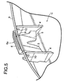
- a wheel W for an automobile comprises a rim 1 on an outer periphery of which a tire T is mounted, and a spoke 2 coupled to an axially central portion of an inner periphery of the rim 1.
- the rim 1 is provided at its laterally opposite ends with cylindrical flanged portions 1a with which left and right bead portions of the tire T are brought into close contact, and an annular locking recess 3 is formed in an inner peripheral surface of each of the cylindrical portions 1a.
- a wheel cap C is mounted to a wheel-cap mounting structure according to the present invention by utilizing the annular locking recesses 3 to cover an outer side face of the wheel W.
- the wheel cap C is made of a synthetic resin, and a plurality of pairs of support plates 4, 4 are projectingly provided on an inner wall of the wheel cap and arranged annularly at equal distances so that the support plates in each pair are opposed to each other in a circumferential direction.
- all the pairs of support plates 4, 4 are fitted to the inner peripheral surface of the cylindrical portion 1a of the rim 1 by cooperation with each other, and arranged so that the concentricity of the wheel cap C relative to the wheel W can be ensured.
- a pair of support legs 5, 5 are integrally formed on each pair of the support plates 4, 4 to extend from base portions of their opposed surfaces.
- Each of the support legs 5, 5 is in the form of a plate thin in a radial direction of the wheel cap C, and tip ends of the support legs 5,5 forming a V-shape by cooperation with each other are integrally connected to each other.
- the support legs 5, 5 formed of a synthetic resin into the plate shape and integrally connected at their tip ends to each other has a bending elasticity in the radial direction of the wheel cap C, but exhibits a strong rigidity in the other directions.
- a locking claw 6 is integrally formed at a connection between the tip ends of the support legs 5, 5, so that it can be engaged into the locking recess 3 in the rim 1.
- the locking claw 6 is ridged radially outwards from the wheel W and formed into a chevron-shape having a ridgeline extending in a circumferential direction of the wheel cap C. Therefore, the locking claw 6 has a pair of slopes 6a and 6b (see Fig.2) inclined in opposite directions from each other in an axial direction of the cylindrical portion 1a.
- a plurality of notched grooves 7 are formed in a top of a chevron face of the locking claw 6 in a direction crossing the ridgeline.
- a retaining groove 8 is formed in a back face of the locking claw 6 opposite from the chevron face, to extend in the circumferential direction of the wheel cap C.
- An annular setting spring 9 common to all the locking claws 6 is mounted in the retaining groove 8, so that all the locking claws 6 are biased radially outwards by a radially outward tension of the setting spring 9.
- the setting spring 9 is supported in a floated manner and concentrically with the wheel cap C by all the support legs 5, 5.
- all the locking claws 6 are arranged so that an inscribed circle contacting with the tops of the chevron portions of the locking claws 6 is slightly larger than the inner diameter of the annular locking recess 3 in a state in which the locking claws 6 are biased radially outwards by the tension of the setting spring 9.
- angular U-shaped restricting notches 10, 10 for receiving the setting spring 9 are formed at tip ends of the support plates 4, 4 in each pair, respectively. Opposed inner sidewalls of the restricting notches 10, 10 are usually not in contact with the setting spring 9, but when the setting spring 9 is eccentrically moved from the center of the wheel cap C due to the deformation of one or more pairs of support legs 5, 5, the inner sidewall of one of the restricting notches 10, 10 receives the setting spring 9.
- the wheel cap C To mount the wheel cap C to the wheel W, the wheel cap C is pushed toward an outer side face of the wheel W. This causes all the locking claws 6 to move radially inwards, while the slope 6a closer to the inside of the cylindrical portion 1a is slid on the inner peripheral surface of the cylindrical portion 1a of the rim 1, whereby the support legs 5, 5 are flexed radially inwards against the tension of the setting spring 9.
- the locking claw 6 reaches a position in the locking recess 3 of the cylindrical portion 1a of the rim 1, the locking claw 6 is engaged into the locking recess 3 under the action of a resilient force of the setting spring 9, and the wheel cap C is retained on the rim 1 by an engagement force in a state to cover the outer side face of the wheel W.
- a tool such as a screwdriver is insert between an outer peripheral edge of the wheel cap C and the rim 1 to pull back the wheel cap C outwardly sideways against the engagement force, whereby each of the locking claws 6 is disengaged from the locking recess 3, while the slope 6b closer the outside of the cylindrical portion 1a is slid on the peripheral edge of the locking recess 3 opposed to the slope 3b. Therefore, each of the locking claws 6 can be then slid smoothly on the inner peripheral surface of the cylindrical portion 1a, whereby the wheel cap C can be removed.
- Each pair of the support legs 5, 5 supporting the locking claw 6 extend from the base portions of the opposed surfaces of the pair of support plates 4, 4, and their tip ends are integrally connected to each other to form the V-shape. Therefore, each of the support legs 5, 5 is inclined with respect to each of the support plates 4, 4, and its effective length can be set at a large value, as compared with the conventional support leg provided to rise vertically at the central portion of the bridging rod. Further, the effective length can be freely set by appropriately selecting the width of the support legs 5,5 and the angle of the V-shape. Therefore, the bending spring constant of each of the support legs 5, 5 in the radial direction of the wheel cap C can be reduced to enhance the flexibility of the support legs 5, 5, thereby improving the durability of the support legs 5, 5 and the mounting property of the wheel cap C.
- the support legs 5, 5 arranged in the V-shape with the tip ends integrally connected to each other exhibit a high rigidity in a direction of arrangement of the support legs, that is, in the circumferential direction of the wheel cap C. Therefore, it is possible to reliably prevent the falling of the support legs 5, 5 in the circumferential direction of the wheel cap C, to contribute to the stabilization of the mounting attitude of the wheel cap C.
- the plurality of notched grooves 7 formed in the top of the chevron face of each of the locking claws 6 function to increase the contact pressure between the locking claw 6 and a bottom surface of the locking recess 3 in the rim 1 thereby facilitating the elimination of soil and sand existing in the contact area between the locking claw 6 and the bottom surface, and to receive the eliminated soil and sand.
- each of the plate-shaped support legs 5 may be replaced by a bar-shaped support leg.
- a plurality of pairs of support plates are projectingly provided on an inner wall of the wheel cap made of a synthetic resin and arranged annularly so that the support plates in each pair are opposed to each other in a circumferential direction.
- a pair of elastic support legs extending from opposed surfaces of the support plates in each pair are integrally connected to each other to form a V-shape.
- a locking claw is formed on a connection between the support legs and capable of being engaged into a locking recess in an inner peripheral surface of a rim of the wheel.
- An annular setting spring is connected to the locking claws for biasing the locking claws in a direction to come into engagement in said locking recess.
Landscapes
- Engineering & Computer Science (AREA)
- Mechanical Engineering (AREA)
- Tires In General (AREA)
- Rolling Contact Bearings (AREA)
- Vehicle Body Suspensions (AREA)
- Sealing Devices (AREA)
- Diaphragms And Bellows (AREA)
- Motor Or Generator Frames (AREA)
- Snaps, Bayonet Connections, Set Pins, And Snap Rings (AREA)
Applications Claiming Priority (2)
| Application Number | Priority Date | Filing Date | Title |
|---|---|---|---|
| JP2002178388A JP3683233B2 (ja) | 2002-06-19 | 2002-06-19 | ホイールキャップの取り付け構造 |
| JP2002178388 | 2002-06-19 |
Publications (3)
| Publication Number | Publication Date |
|---|---|
| EP1375194A2 true EP1375194A2 (fr) | 2004-01-02 |
| EP1375194A3 EP1375194A3 (fr) | 2005-05-04 |
| EP1375194B1 EP1375194B1 (fr) | 2008-06-25 |
Family
ID=29717487
Family Applications (1)
| Application Number | Title | Priority Date | Filing Date |
|---|---|---|---|
| EP03013734A Expired - Lifetime EP1375194B1 (fr) | 2002-06-19 | 2003-06-17 | Structure de montage d'un enjoliveur de roue |
Country Status (7)
| Country | Link |
|---|---|
| US (1) | US6886891B2 (fr) |
| EP (1) | EP1375194B1 (fr) |
| JP (1) | JP3683233B2 (fr) |
| CN (1) | CN1296217C (fr) |
| AT (1) | ATE399098T1 (fr) |
| CA (1) | CA2432765C (fr) |
| DE (1) | DE60321754D1 (fr) |
Cited By (3)
| Publication number | Priority date | Publication date | Assignee | Title |
|---|---|---|---|---|
| FR2962687A1 (fr) * | 2010-07-19 | 2012-01-20 | Peugeot Citroen Automobiles Sa | Enjoliveur pour une roue d'un vehicule comportant un anneau circulaire et procede de montage ou de demontage de cet anneau sur l'enjoliveur |
| WO2015092082A1 (fr) * | 2013-12-19 | 2015-06-25 | Zanini Auto Grup, S.A. | Enjoliveur pour des roues de véhicules |
| CN110406310A (zh) * | 2019-07-30 | 2019-11-05 | 广州市金钟汽车零件股份有限公司 | 一种轮毂装饰盖及金属卡子 |
Families Citing this family (16)
| Publication number | Priority date | Publication date | Assignee | Title |
|---|---|---|---|---|
| US20100090500A1 (en) * | 2008-10-13 | 2010-04-15 | Cnh America Llc | Elements of the body of a Vehicle |
| CN101850693B (zh) * | 2010-06-21 | 2014-12-24 | 宁波信泰机械有限公司 | 一种改进结构的轮圈盖 |
| JP5597588B2 (ja) * | 2011-03-31 | 2014-10-01 | 株式会社ファルテック | ホイールカバー |
| CN102555663A (zh) * | 2012-02-07 | 2012-07-11 | 力帆实业(集团)股份有限公司 | 轿车轮辋与装饰罩连接结构 |
| CN102555664A (zh) * | 2012-02-07 | 2012-07-11 | 力帆实业(集团)股份有限公司 | 轿车轮辋护罩 |
| US9370965B2 (en) * | 2014-05-19 | 2016-06-21 | Jesse L. Bradley | Truck wheel turbulence shield |
| AU2018211034B2 (en) * | 2017-01-17 | 2020-09-03 | Moochout Llc | Wheel cover quick mount |
| US12344037B2 (en) | 2017-01-17 | 2025-07-01 | Moochout Llc | Passenger vehicle wheel cover |
| US11584156B2 (en) | 2017-01-17 | 2023-02-21 | Moochout Llc | Systems and methods for locking and stabilizing a wheel cover assembly |
| US12064995B2 (en) | 2017-01-17 | 2024-08-20 | Moochout Llc | Wheel cover quick mount |
| TWI621543B (zh) * | 2017-04-20 | 2018-04-21 | 佳冠材料實業有限公司 | 輪圈蓋卡固結構 |
| CN109702467B (zh) * | 2018-12-07 | 2023-11-03 | 上海蔚来汽车有限公司 | 一种车轮自动安装方法及车轮自动安装装置 |
| CN112193784B (zh) * | 2020-10-20 | 2021-11-30 | 普迈科(芜湖)机械有限公司 | 一种钩杆可调的高速理瓶机 |
| CN114475082B (zh) * | 2020-10-27 | 2024-02-27 | 上海汽车集团股份有限公司 | 一种车轮嵌件、车轮及汽车 |
| CN117719271B (zh) * | 2024-02-18 | 2024-05-03 | 江苏盖兹汽车零部件有限公司 | 一种具有降低风阻、防污效果的轮毂通风口镶件 |
| WO2025264466A1 (fr) * | 2024-06-19 | 2025-12-26 | Neo Design, LLC | Bague réglable pour enjoliveur de roue universel à bordure |
Family Cites Families (16)
| Publication number | Priority date | Publication date | Assignee | Title |
|---|---|---|---|---|
| DE2943139A1 (de) * | 1979-10-25 | 1981-05-07 | Daimler-Benz Ag, 7000 Stuttgart | Radblende, insbesondere fuer raeder von personenkraftwagen |
| DE3039219C2 (de) * | 1980-10-17 | 1986-11-20 | Daimler-Benz Ag, 7000 Stuttgart | Radblendenbefestigung für Kraftfahrzeuge |
| US4740038A (en) * | 1986-05-08 | 1988-04-26 | Sakae Riken Kogyo Co., Ltd. | Wheel cover |
| JPS62279101A (ja) * | 1986-05-28 | 1987-12-04 | Kanto Seiki Co Ltd | ホイ−ルカバ−の装着装置 |
| JPS6389802A (ja) | 1986-10-03 | 1988-04-20 | Mitsubishi Electric Corp | 繊維強化プラスチツク製反射鏡 |
| CA1309123C (fr) * | 1986-08-04 | 1992-10-20 | Noboru Shirai | Couvre-roue |
| EP0386803A1 (fr) * | 1986-08-04 | 1990-09-12 | Kabushiki Kaisha Tokai Rika Denki Seisakusho | Enjoliveur de roue |
| JP2559727B2 (ja) * | 1987-02-24 | 1996-12-04 | 株式会社カンセイ | ホイ−ルカバ−取付装置 |
| US4917441A (en) * | 1987-07-13 | 1990-04-17 | Kanto Seiki Co., Ltd. | Plastic wheel cover with fastening device |
| JP2635335B2 (ja) | 1987-09-30 | 1997-07-30 | 株式会社カンセイ | ホイールカバー取付装置 |
| JP2721010B2 (ja) * | 1988-07-06 | 1998-03-04 | 株式会社カンセイ | ホイールカバーの取付装置 |
| JPH0365402A (ja) * | 1989-08-04 | 1991-03-20 | Kanto Seiki Co Ltd | ホイールカバー取付装置 |
| US5161860A (en) * | 1990-06-01 | 1992-11-10 | Toyoda Gosei Co., Ltd. | Wheel cap |
| CN2351308Y (zh) * | 1999-01-14 | 1999-12-01 | 勤力弹簧工业股份有限公司 | 车轮盖闪烁装置 |
| US6139114A (en) * | 1999-04-09 | 2000-10-31 | Wang; Hung-Sheng | Rim disc adjustable to different sized rims |
| US6371570B1 (en) * | 2000-11-08 | 2002-04-16 | Johnny Wang | Securing member for a steel ring of a wheel cover |
-
2002
- 2002-06-19 JP JP2002178388A patent/JP3683233B2/ja not_active Expired - Fee Related
-
2003
- 2003-06-12 US US10/459,710 patent/US6886891B2/en not_active Expired - Fee Related
- 2003-06-13 CN CNB031427731A patent/CN1296217C/zh not_active Expired - Fee Related
- 2003-06-17 DE DE60321754T patent/DE60321754D1/de not_active Expired - Lifetime
- 2003-06-17 EP EP03013734A patent/EP1375194B1/fr not_active Expired - Lifetime
- 2003-06-17 AT AT03013734T patent/ATE399098T1/de not_active IP Right Cessation
- 2003-06-18 CA CA002432765A patent/CA2432765C/fr not_active Expired - Fee Related
Cited By (4)
| Publication number | Priority date | Publication date | Assignee | Title |
|---|---|---|---|---|
| FR2962687A1 (fr) * | 2010-07-19 | 2012-01-20 | Peugeot Citroen Automobiles Sa | Enjoliveur pour une roue d'un vehicule comportant un anneau circulaire et procede de montage ou de demontage de cet anneau sur l'enjoliveur |
| WO2012010778A1 (fr) * | 2010-07-19 | 2012-01-26 | Peugeot Citroën Automobiles SA | Enjoliveur pour une roue d'un vehicule comportant un anneau circulaire et procede de montage ou de demontage de cet anneau sur l'enjoliveur |
| WO2015092082A1 (fr) * | 2013-12-19 | 2015-06-25 | Zanini Auto Grup, S.A. | Enjoliveur pour des roues de véhicules |
| CN110406310A (zh) * | 2019-07-30 | 2019-11-05 | 广州市金钟汽车零件股份有限公司 | 一种轮毂装饰盖及金属卡子 |
Also Published As
| Publication number | Publication date |
|---|---|
| ATE399098T1 (de) | 2008-07-15 |
| CN1468738A (zh) | 2004-01-21 |
| EP1375194A3 (fr) | 2005-05-04 |
| DE60321754D1 (de) | 2008-08-07 |
| CA2432765A1 (fr) | 2003-12-19 |
| JP2004017880A (ja) | 2004-01-22 |
| EP1375194B1 (fr) | 2008-06-25 |
| CA2432765C (fr) | 2006-12-12 |
| JP3683233B2 (ja) | 2005-08-17 |
| CN1296217C (zh) | 2007-01-24 |
| US6886891B2 (en) | 2005-05-03 |
| US20040041459A1 (en) | 2004-03-04 |
Similar Documents
| Publication | Publication Date | Title |
|---|---|---|
| US6886891B2 (en) | Wheel-cap mounting structure | |
| US20020029627A1 (en) | Housing for a tire pressure sensor for a motor vehicle | |
| US8926244B2 (en) | Member fastening structure and clip for fastening member | |
| US6682151B1 (en) | Wheel cover retention apparatus | |
| US10240625B2 (en) | Assembly unit | |
| US6726290B1 (en) | Wheel cover | |
| US5161860A (en) | Wheel cap | |
| KR20060117181A (ko) | 축용 스냅 링 | |
| US4709967A (en) | Wheel cap | |
| EP2021191B1 (fr) | Systeme de retention pour enjoliveur de roue en plastique | |
| JP2023075763A (ja) | ホイールキャップ | |
| US4708398A (en) | Wheel cover retention system with pilot ribs | |
| US6473391B1 (en) | Optical disk | |
| JPH0747361B2 (ja) | 自動車用ホイールカバー | |
| US2728610A (en) | Ornamental and protective vehicle wheel assembly | |
| US4943122A (en) | Center hub cap for vehicle wheels | |
| JPS63134303A (ja) | ホイ−ルカバ− | |
| US8746518B2 (en) | Spacer for spacing wheel rim from compartment floor | |
| JP4123142B2 (ja) | ホイールカバー | |
| JP2003054205A (ja) | ホイールカバー | |
| JPS581045Y2 (ja) | ホイ−ルキヤツプ | |
| JP2598294Y2 (ja) | 携帯用時計のスタンド構造 | |
| JPS5855046Y2 (ja) | 樹脂製センタ−キャップ | |
| JPH0511681Y2 (fr) | ||
| CN108730344A (zh) | 圆柱滚子轴承用保持架及圆柱滚子轴承 |
Legal Events
| Date | Code | Title | Description |
|---|---|---|---|
| PUAI | Public reference made under article 153(3) epc to a published international application that has entered the european phase |
Free format text: ORIGINAL CODE: 0009012 |
|
| AK | Designated contracting states |
Kind code of ref document: A2 Designated state(s): AT BE BG CH CY CZ DE DK EE ES FI FR GB GR HU IE IT LI LU MC NL PT RO SE SI SK TR |
|
| AX | Request for extension of the european patent |
Extension state: AL LT LV MK |
|
| PUAL | Search report despatched |
Free format text: ORIGINAL CODE: 0009013 |
|
| AK | Designated contracting states |
Kind code of ref document: A3 Designated state(s): AT BE BG CH CY CZ DE DK EE ES FI FR GB GR HU IE IT LI LU MC NL PT RO SE SI SK TR |
|
| AX | Request for extension of the european patent |
Extension state: AL LT LV MK |
|
| 17P | Request for examination filed |
Effective date: 20050509 |
|
| AKX | Designation fees paid |
Designated state(s): AT BE BG CH CY CZ DE DK EE ES FI FR GB GR HU IE IT LI LU MC NL PT RO SE SI SK TR |
|
| RAP1 | Party data changed (applicant data changed or rights of an application transferred) |
Owner name: MORIROKU KABUSHIKI KAISHA |
|
| GRAP | Despatch of communication of intention to grant a patent |
Free format text: ORIGINAL CODE: EPIDOSNIGR1 |
|
| GRAS | Grant fee paid |
Free format text: ORIGINAL CODE: EPIDOSNIGR3 |
|
| GRAA | (expected) grant |
Free format text: ORIGINAL CODE: 0009210 |
|
| AK | Designated contracting states |
Kind code of ref document: B1 Designated state(s): AT BE BG CH CY CZ DE DK EE ES FI FR GB GR HU IE IT LI LU MC NL PT RO SE SI SK TR |
|
| REG | Reference to a national code |
Ref country code: GB Ref legal event code: FG4D |
|
| RIN1 | Information on inventor provided before grant (corrected) |
Inventor name: SUZUKI, YOUSUKE Inventor name: SUGAUCHI, YASUFUMI Inventor name: HARA, KOUICHI Inventor name: UCHIDA, OSAMU Inventor name: IKUMA, YUUSUKE |
|
| REG | Reference to a national code |
Ref country code: CH Ref legal event code: EP |
|
| REF | Corresponds to: |
Ref document number: 60321754 Country of ref document: DE Date of ref document: 20080807 Kind code of ref document: P |
|
| REG | Reference to a national code |
Ref country code: IE Ref legal event code: FG4D |
|
| PG25 | Lapsed in a contracting state [announced via postgrant information from national office to epo] |
Ref country code: SI Free format text: LAPSE BECAUSE OF FAILURE TO SUBMIT A TRANSLATION OF THE DESCRIPTION OR TO PAY THE FEE WITHIN THE PRESCRIBED TIME-LIMIT Effective date: 20080625 Ref country code: FI Free format text: LAPSE BECAUSE OF FAILURE TO SUBMIT A TRANSLATION OF THE DESCRIPTION OR TO PAY THE FEE WITHIN THE PRESCRIBED TIME-LIMIT Effective date: 20080625 |
|
| PG25 | Lapsed in a contracting state [announced via postgrant information from national office to epo] |
Ref country code: NL Free format text: LAPSE BECAUSE OF FAILURE TO SUBMIT A TRANSLATION OF THE DESCRIPTION OR TO PAY THE FEE WITHIN THE PRESCRIBED TIME-LIMIT Effective date: 20080625 Ref country code: AT Free format text: LAPSE BECAUSE OF FAILURE TO SUBMIT A TRANSLATION OF THE DESCRIPTION OR TO PAY THE FEE WITHIN THE PRESCRIBED TIME-LIMIT Effective date: 20080625 |
|
| NLV1 | Nl: lapsed or annulled due to failure to fulfill the requirements of art. 29p and 29m of the patents act | ||
| PG25 | Lapsed in a contracting state [announced via postgrant information from national office to epo] |
Ref country code: PT Free format text: LAPSE BECAUSE OF FAILURE TO SUBMIT A TRANSLATION OF THE DESCRIPTION OR TO PAY THE FEE WITHIN THE PRESCRIBED TIME-LIMIT Effective date: 20081125 Ref country code: ES Free format text: LAPSE BECAUSE OF FAILURE TO SUBMIT A TRANSLATION OF THE DESCRIPTION OR TO PAY THE FEE WITHIN THE PRESCRIBED TIME-LIMIT Effective date: 20081006 Ref country code: CZ Free format text: LAPSE BECAUSE OF FAILURE TO SUBMIT A TRANSLATION OF THE DESCRIPTION OR TO PAY THE FEE WITHIN THE PRESCRIBED TIME-LIMIT Effective date: 20080625 Ref country code: SE Free format text: LAPSE BECAUSE OF FAILURE TO SUBMIT A TRANSLATION OF THE DESCRIPTION OR TO PAY THE FEE WITHIN THE PRESCRIBED TIME-LIMIT Effective date: 20080925 |
|
| PG25 | Lapsed in a contracting state [announced via postgrant information from national office to epo] |
Ref country code: RO Free format text: LAPSE BECAUSE OF FAILURE TO SUBMIT A TRANSLATION OF THE DESCRIPTION OR TO PAY THE FEE WITHIN THE PRESCRIBED TIME-LIMIT Effective date: 20080625 Ref country code: BE Free format text: LAPSE BECAUSE OF FAILURE TO SUBMIT A TRANSLATION OF THE DESCRIPTION OR TO PAY THE FEE WITHIN THE PRESCRIBED TIME-LIMIT Effective date: 20080625 Ref country code: SK Free format text: LAPSE BECAUSE OF FAILURE TO SUBMIT A TRANSLATION OF THE DESCRIPTION OR TO PAY THE FEE WITHIN THE PRESCRIBED TIME-LIMIT Effective date: 20080625 |
|
| PG25 | Lapsed in a contracting state [announced via postgrant information from national office to epo] |
Ref country code: BG Free format text: LAPSE BECAUSE OF FAILURE TO SUBMIT A TRANSLATION OF THE DESCRIPTION OR TO PAY THE FEE WITHIN THE PRESCRIBED TIME-LIMIT Effective date: 20080925 Ref country code: DK Free format text: LAPSE BECAUSE OF FAILURE TO SUBMIT A TRANSLATION OF THE DESCRIPTION OR TO PAY THE FEE WITHIN THE PRESCRIBED TIME-LIMIT Effective date: 20080625 Ref country code: EE Free format text: LAPSE BECAUSE OF FAILURE TO SUBMIT A TRANSLATION OF THE DESCRIPTION OR TO PAY THE FEE WITHIN THE PRESCRIBED TIME-LIMIT Effective date: 20080625 |
|
| PLBE | No opposition filed within time limit |
Free format text: ORIGINAL CODE: 0009261 |
|
| STAA | Information on the status of an ep patent application or granted ep patent |
Free format text: STATUS: NO OPPOSITION FILED WITHIN TIME LIMIT |
|
| 26N | No opposition filed |
Effective date: 20090326 |
|
| PG25 | Lapsed in a contracting state [announced via postgrant information from national office to epo] |
Ref country code: IT Free format text: LAPSE BECAUSE OF FAILURE TO SUBMIT A TRANSLATION OF THE DESCRIPTION OR TO PAY THE FEE WITHIN THE PRESCRIBED TIME-LIMIT Effective date: 20080625 |
|
| PG25 | Lapsed in a contracting state [announced via postgrant information from national office to epo] |
Ref country code: MC Free format text: LAPSE BECAUSE OF NON-PAYMENT OF DUE FEES Effective date: 20090630 |
|
| REG | Reference to a national code |
Ref country code: CH Ref legal event code: PL |
|
| REG | Reference to a national code |
Ref country code: FR Ref legal event code: ST Effective date: 20100226 |
|
| REG | Reference to a national code |
Ref country code: IE Ref legal event code: MM4A |
|
| PG25 | Lapsed in a contracting state [announced via postgrant information from national office to epo] |
Ref country code: FR Free format text: LAPSE BECAUSE OF NON-PAYMENT OF DUE FEES Effective date: 20090630 Ref country code: LI Free format text: LAPSE BECAUSE OF NON-PAYMENT OF DUE FEES Effective date: 20090630 Ref country code: IE Free format text: LAPSE BECAUSE OF NON-PAYMENT OF DUE FEES Effective date: 20090617 Ref country code: CH Free format text: LAPSE BECAUSE OF NON-PAYMENT OF DUE FEES Effective date: 20090630 |
|
| PG25 | Lapsed in a contracting state [announced via postgrant information from national office to epo] |
Ref country code: GR Free format text: LAPSE BECAUSE OF FAILURE TO SUBMIT A TRANSLATION OF THE DESCRIPTION OR TO PAY THE FEE WITHIN THE PRESCRIBED TIME-LIMIT Effective date: 20080926 |
|
| PG25 | Lapsed in a contracting state [announced via postgrant information from national office to epo] |
Ref country code: LU Free format text: LAPSE BECAUSE OF NON-PAYMENT OF DUE FEES Effective date: 20090617 |
|
| PG25 | Lapsed in a contracting state [announced via postgrant information from national office to epo] |
Ref country code: HU Free format text: LAPSE BECAUSE OF FAILURE TO SUBMIT A TRANSLATION OF THE DESCRIPTION OR TO PAY THE FEE WITHIN THE PRESCRIBED TIME-LIMIT Effective date: 20081226 |
|
| PG25 | Lapsed in a contracting state [announced via postgrant information from national office to epo] |
Ref country code: TR Free format text: LAPSE BECAUSE OF FAILURE TO SUBMIT A TRANSLATION OF THE DESCRIPTION OR TO PAY THE FEE WITHIN THE PRESCRIBED TIME-LIMIT Effective date: 20080625 |
|
| PGFP | Annual fee paid to national office [announced via postgrant information from national office to epo] |
Ref country code: GB Payment date: 20110603 Year of fee payment: 9 |
|
| PG25 | Lapsed in a contracting state [announced via postgrant information from national office to epo] |
Ref country code: CY Free format text: LAPSE BECAUSE OF FAILURE TO SUBMIT A TRANSLATION OF THE DESCRIPTION OR TO PAY THE FEE WITHIN THE PRESCRIBED TIME-LIMIT Effective date: 20080625 |
|
| GBPC | Gb: european patent ceased through non-payment of renewal fee |
Effective date: 20120617 |
|
| REG | Reference to a national code |
Ref country code: DE Ref legal event code: R119 Ref document number: 60321754 Country of ref document: DE Effective date: 20130101 |
|
| PG25 | Lapsed in a contracting state [announced via postgrant information from national office to epo] |
Ref country code: GB Free format text: LAPSE BECAUSE OF NON-PAYMENT OF DUE FEES Effective date: 20120617 Ref country code: DE Free format text: LAPSE BECAUSE OF NON-PAYMENT OF DUE FEES Effective date: 20130101 |
|
| PGFP | Annual fee paid to national office [announced via postgrant information from national office to epo] |
Ref country code: DE Payment date: 20110331 Year of fee payment: 9 |