EP1375406A2 - Fadenwickelhülse mit abnehmbarer Endkappe - Google Patents
Fadenwickelhülse mit abnehmbarer Endkappe Download PDFInfo
- Publication number
- EP1375406A2 EP1375406A2 EP03014733A EP03014733A EP1375406A2 EP 1375406 A2 EP1375406 A2 EP 1375406A2 EP 03014733 A EP03014733 A EP 03014733A EP 03014733 A EP03014733 A EP 03014733A EP 1375406 A2 EP1375406 A2 EP 1375406A2
- Authority
- EP
- European Patent Office
- Prior art keywords
- end ring
- tubular body
- recesses
- tube according
- yarn
- Prior art date
- Legal status (The legal status is an assumption and is not a legal conclusion. Google has not performed a legal analysis and makes no representation as to the accuracy of the status listed.)
- Withdrawn
Links
Images


Classifications
-
- B—PERFORMING OPERATIONS; TRANSPORTING
- B65—CONVEYING; PACKING; STORING; HANDLING THIN OR FILAMENTARY MATERIAL
- B65H—HANDLING THIN OR FILAMENTARY MATERIAL, e.g. SHEETS, WEBS, CABLES
- B65H75/00—Storing webs, tapes, or filamentary material, e.g. on reels
- B65H75/02—Cores, formers, supports, or holders for coiled, wound, or folded material, e.g. reels, spindles, bobbins, cop tubes, cans, mandrels or chucks
- B65H75/18—Constructional details
- B65H75/182—Identification means
-
- B—PERFORMING OPERATIONS; TRANSPORTING
- B65—CONVEYING; PACKING; STORING; HANDLING THIN OR FILAMENTARY MATERIAL
- B65H—HANDLING THIN OR FILAMENTARY MATERIAL, e.g. SHEETS, WEBS, CABLES
- B65H75/00—Storing webs, tapes, or filamentary material, e.g. on reels
- B65H75/02—Cores, formers, supports, or holders for coiled, wound, or folded material, e.g. reels, spindles, bobbins, cop tubes, cans, mandrels or chucks
- B65H75/18—Constructional details
- B65H75/28—Arrangements for positively securing ends of material
-
- B—PERFORMING OPERATIONS; TRANSPORTING
- B65—CONVEYING; PACKING; STORING; HANDLING THIN OR FILAMENTARY MATERIAL
- B65H—HANDLING THIN OR FILAMENTARY MATERIAL, e.g. SHEETS, WEBS, CABLES
- B65H2701/00—Handled material; Storage means
- B65H2701/30—Handled filamentary material
- B65H2701/31—Textiles threads or artificial strands of filaments
Definitions
- the present invention relates generally to yarn carriers and, more particularly, to yarn winding tubes suitable for high speed winding operations.
- Yarn packs are formed by winding yarn onto carriers or winding tubes that are rotated at high speed, sometimes in excess of 6,000 RPM.
- the winding tubes which are typically made of paperboard or plastic, are arranged consecutively so that the yarn can be transferred from one tube to the next without having to stop the winding process.
- the tubes often define a start-up or pick-up groove in the body of the tube for capturing the yarn at the initial contact of the yarn and tube.
- the start-up groove of a conventional winding tube is typically formed by cutting or indenting the groove in the side of the tube body.
- some winding tubes incorporate an end ring on the end of the tube that forms a start-up groove with the tube body when the end ring is releasably secured thereto, such as by press fitting or by screwing a threaded end ring to the tube body.
- the start-up groove is defined by a scallop or indentation formed in the end ring and a shoulder defined by the tube when the end ring is secured to the tube.
- One possible solution could be to reduce the size of the indentation defined by the end ring. However, providing a smaller indentation may make it more difficult for the yarn to catch in the groove, as the yarn must be positioned at the precise location of the groove as the tube revolves.
- Another possible solution could be to provide a threaded end ring that can be screwed onto an end of the tube. Threaded end rings are also problematic, however, as they are more difficult to manufacture. The threads are also susceptible to damage over time, which eventually leads to replacement of the entire tube.
- An important feature in winding tubes is the means for identifying the particular type of yarn that is wound on the tube without requiring a detailed inspection of the yarn.
- One conventional method of identifying the yarn type includes marking the end of the winding tube with a colored marker or the like, or by placing a sticker or painting a symbol on the end of the tube. While these methods identify the yarn during a particular winding operation, the markings may not be applicable to future yarns, which limits the marked tubes to a particular type of yarn. Thus, tubes must be maintained in inventory for each type of yarn, which adds to the cost and complexity of the winding operation.
- the present invention relates to a winding tube for use in winding yarn or fibers about the tube in a winding operation, wherein yarn or fibers are wound thereon and unwound therefrom.
- the tube includes an end ring defining at least two recesses in an end face thereof that are spaced apart from each other so that the end ring can be secured and aligned with the body of the tube while providing at least two start-up grooves for capturing the yarn.
- the end ring defines at least two more recesses defined by the opposite end face of the end ring such that the end ring is reversible, which makes mounting the end ring easier when preparing the tube for the winding process.
- a tube for use in a textile winding operation includes a body having opposed ends and an outer surface extending therebetween.
- the body defines a generally radially extending shoulder proximate at least one end thereof, and in one embodiment defines a shoulder at each end of the tube.
- the body has a reduced diameter portion that extends from the end of the tube to the respective shoulder.
- the tube also includes an end ring having opposing end faces and that is operable to releaseably engage the end of the body proximate the shoulder.
- the end ring can be formed from a variety of materials, such as polymers, paperboards, composites, resins, metals, and combinations thereof.
- the end ring has an inner diameter adapted to mate with the reduced diameter portion of the body and defines at least two recesses in at least one of the opposing end faces thereof.
- each of the recesses forms a start-up region with the shoulder for capturing yarn.
- the end ring defines two recesses in one end face and two recesses on the opposite end face.
- each end face are evenly spaced apart about the circumference of the end ring according to a preferred embodiment, such as by about 180 degrees if two recesses are provided on an end face, and the recesses in each end face are circumferentially offset from the recesses of the opposite end face, such as by about 90 degrees if two recesses are provided on each end face.
- the end ring is reversible so that at least two start-up regions are provided for capturing yarn regardless of the mounting orientation of the end ring in relation to the body of the tube.
- an end ring according to the present invention can be utilized at either or both ends of the tube so that either end of the tube can be used to initially capture yarn during the winding operation.
- the recesses can have many shapes, and preferably have a curved shape.
- the recesses can also be symmetrical or asymmetrical in the circumferential direction.
- the recesses have an asymmetrical ramp shape that provides one start-up region per recess.
- oppositely oriented ramp-shaped recesses can be positioned along the same side of the end ring such that the tube can be rotated in either direction and still capture yarn.
- Symmetrical recesses are also capable of capturing yarn regardless of the tube's rotational direction.
- the end ring also includes means for identifying the type of yarn to be captured during the winding operation.
- the end ring is colored on at least a part of its surface to indicate a corresponding type of yarn. In this manner, the end ring can be removed and replaced on the body of the tube according to the type of yarn used in a particular winding process.
- the winding tube of the present invention has a longer lifespan compared to conventional tubes, as the end rings can be replaced and/or discarded when they become worn instead of replacing the entire winding tube.
- the end ring of the present invention is easily aligned and secured to the body of the tube and defines recesses spaced along each end face of the end ring for forming start-up regions with the tube body.
- the end ring of the present invention can be selected so as to indicate what type of yarn is wound about the tube, which improves efficiency of the winding operation.
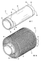
- Figures 1-3 show various views of a winding tube 10 according to the present invention.
- the tube 10 is suitable for high speed yarn winding operations, such as during the manufacture of textiles.
- a continuous strand of yarn 12 is wound about the tube 10 to form a pack 14 .
- the yarn 12 is wound about a plurality of consecutively aligned tubes and transferred from one tube to the next by a yarn guide (not shown) according to known winding techniques.
- the yarn 12 includes a lead portion 20 that contacts the tube first and is wound about an end thereof, whereby the yarn is wrapped about the tube according to conventional practice to form the pack 14.
- the yarn 12 also includes a tail portion 22, as discussed more fully below.
- the tube 10 includes a hollow, elongate body 24 that is formed of a durable material, such as paperboard, polymers (including thermoplastics), metal, resins, composites, and combinations thereof.
- the body 24 preferably is suitable for repeated use through many winding operations, and includes opposing ends 26, 28 and an outer surface 30 extending therebetween. It should be noted that the outer surface 30 of the body 24 is shown as having a solid appearance, but the outer surface and body could also be perforated or define openings therein, as is common with dye tubes and the like.
- the yarn 12 is wound into the pack 14 about the outer surface 30 of the body 24 of the tube 10.
- the body 24 also has a reduced diameter portion 34 at one of the ends 26, 28 to define a generally radially extending shoulder 32 and, in one embodiment, the body has reduced diameter portions and shoulders at both ends.
- the reduced diameter portions 34 can have smooth or rough surfaces.
- the radial distance between the outer surface 30 and reduced diameter portion 34 of the body 24 is shown as thickness t , which can vary in length, but is generally about one-third to two-thirds the thickness of the body, and preferably about one-half the thickness of the body.
- the tube 10 also includes an end ring 40 that is sized to mate with a respective end 26, 28 of the body 24. More specifically, the end ring 40 has an inner surface 42 that engages the reduced diameter portion 34 of the tube body 24 in a frictional or press-fit relationship, and an outer surface 44 that is substantially flush with the outer surface 30 of the body 24 when the end ring 40 is secured to the body.
- the end ring 40 therefore has first and second end faces 46, 48 that have lengths or thicknesses that are substantially equivalent to the radial depth or thickness t of the shoulder 32.
- the reduced diameter portion 34 of the tube body 24 can have a rough surface to further assist in the frictional relationship between the end ring 40 and the tube body.
- end faces 46 , 48 and/or the shoulder 32 may also have non-smooth or textured surfaces to assist in capturing yarn therebetween.
- the end ring 40 is preferably formed of a resilient and durable material.
- the end ring can be formed from polymers, paperboards, composites, resins, metal, or combinations thereof.
- Figures 3-5 show various embodiments of the end ring 40.
- each end face 46, 48 of the end ring 40 defines at least two recesses 50.
- the end ring 40 can be formed so as to define at least two recesses 50 in only the first end face 46 thereof, although it is more desirable that each end face 46, 48 define recesses so that either end of the end ring can form a plurality of start-up regions 52 with the shoulder 32, as discussed below.
- the recesses 50 preferably have a curved shape, although other shapes are also possible.
- Figures 4a-4d show various embodiment of the end ring 40, including end rings defining recesses 50 shaped as an asymmetrical ramp (Figure 4a), a stepped ramp ( Figure 4b), a parabolic curve (Figure 4c), and a modified asymmetrical ramp ( Figure 4d).
- Figures 4a-4d are asymmetrical in shape, they are most effective when the tube 10 is rotated in a particular direction (clockwise as the end rings are depicted in Figures 4a-4d).
- the symmetrical recesses 50 shown in Figures 1-3 are effective for trapping yarn regardless of the rotational direction of the tube 10.
- oppositely oriented recesses 50 can be positioned on the same side of the end ring 40 .
- Figure 5 shows such an arrangement using the parabolic curve shape shown in Figure 4c. It should also be noted that while only a single recess 50 is shown in the embodiments of Figure 4, more than one recess is possible on the same end face of the end ring 40, as well one or more recesses defined by the opposite end face of the end ring. Likewise, the embodiment shown in Figure 5 could be repeated one or more times on each end face 46, 48 of the end ring 40.
- the recesses 50 of the first end face 46 extend towards the opposite end face 48 of the end ring 40 (and vice versa if recesses are defined by the second end face), but generally do not extend more than about halfway between the opposing end faces 46, 48 . In one embodiment, the recesses extend no more than one-third of the width of the end ring 40.
- the recesses 50 defined by a particular end face 46, 48 are preferably spaced apart about the circumference in a substantially even manner. For example, if two recesses 50 are defined by the first end face 46, the recesses are spaced about 180 degrees apart from one another. If three recesses 50 are defined, the recesses are spaced about 120 degrees from one another, and so on.
- the recesses 50 of the end ring and the shoulder 32 form corresponding start-up regions 52 for capturing the yarn 12 during the winding operation.
- the first end face 46 of the end ring is positioned adjacent to the shoulder 32 of the tube body 24 so as to be in contact therewith except for the recesses 50, which are spaced from the shoulder to form the start-up regions 52 .
- the end ring 40 preferably extends the length of the reduced diameter portion 34 of the tube body 24 so that the end ring and tube body are substantially flush at the respective end 26, 28 of the tube body when the end ring is mounted and releasably secured thereto.
- At least one, and preferably about 3-50, wraps of the yarn 12 are captured and retained in one or more of the start-up regions 52 while the tube 10 is rotated.
- the yarn guide then moves the yarn back and forth along the outer surface 30 of the tube body 24 to form the yam pack 14.
- the end ring 40 can be secured to the reduced diameter portion 34 of the body 24 with a frictional or interference fit.
- Figures 2 and 3 illustrate an alternative embodiment that includes a raised portion 39 extending from the inner surface 42 of the end ring 40 that mates with a groove 41 defined in the recessed portion 34 of the tube body 24 to form a snap fit.
- the circumferential friction between the end ring 40 and the recessed portion 34 of the body 24 is also important, as the start-up regions 52 must be sufficiently stable in the axial and circumferential directions to capture and break the yarn 12 during the winding process.
- the shoulder 32, recessed portion 34 , and/or end face(s) 46, 48 may also be textured or the like.
- Figure 6 shows an alternative embodiment of the tube 10, wherein at least two locking members or pins 65 extend from the recessed portion 34 of the body 24 .
- the pins 65 can be made of the same or different material forming the body 24 , and may be added or applied to the recessed portion 34 during the manufacturing thereof. While the locking members 65 are shown as relatively pin-shaped, the locking members could have alternative shapes as long as the chosen shape permits sufficient locking of the end ring 40 and the body 24. As shown in Figure 6, the end ring 40 defines opening or slots 67 that correspond to the pins 65 and are shaped to receive the pins and lock the end ring 40 to the body.
- the slots 67 have a detent or "L" shape that bias the pins 65 during the locking process, which in the embodiment shown in Figure 6 would include inserting the pins 65 into the slots 67 and rotating the end ring 40 relative to the body 24 until the pins lock the end ring in place. Further to the embodiment shown in Figure 6, it is possible that slots 67 are defined on both sides of the end ring 40 . It is also possible to have pins extending on respective ends of the tube 10.
- Figure 7 shows yet another alternative embodiment of the tube 10, wherein at least two L-shaped locking members 72 extend from the recessed portion 34, and corresponding locking members 74 extend from the inside surface 42 of the end ring 40 .
- the end ring is slid or positioned over the recessed portion 34 and rotated such that the locking members 74 of the end ring engage and abut the L-shaped locking members 72 of the body.
- the continuous strand of yarn 12 is moved by the yarn guide from a finished yarn pack to the empty tube 10.
- the yarn 12 is captured in the start-up region of the tube 10 while the tube rotates.
- the yarn 12 is then broken at the lead portion 20 to form a lead end 16 by stopping or moving the preceding tube having the finished yarn pack wound thereupon while the tube 10 continues to rotate.
- the tail portion 22 of the yarn is moved to a following rotating tube where it is captured by a start-up region thereof.
- the relative movement of the tube 10 and the following tube breaks the tail portion 22 of the yarn 12 to form a tail end 18 .
- the tail portion 22 associated with the tube 10 is broken to form the tail end 18 (and a corresponding lead end of the following tube).
- the process is then repeated for the next tube and so on to form as many yarn packs as desired.
- Figure 3 shows one embodiment of the end ring 40 , wherein the end ring defines at least two recesses 50 on each end face 46, 48 thereof.
- the end ring 40 can be reversed so that the recesses 50 of either end face 46, 48 can form the start-up regions 52 with the respective shoulder 32.
- the recesses on the first end face are rotated or offset about 90 degrees from the recesses on the second end face.
- this design allows an operator to quickly engage the end ring 40 and the tube body 24 without determining which end face defines the recesses 50 for forming the start-up regions 52.
- spacing the recesses 50 as described above allows the end ring 40 to be substantially balanced, which helps prevent the end ring from being mounted unevenly against the tube body 24 .
- end ring 40 Another feature of the end ring 40 is that the end ring can be easily removed and replaced when necessary or desired. For instance, repeated winding operations may cause the recesses 50 of the end ring 40 to degrade slightly over time due to repeated contact with the yarn 12 . When this occurs, the end ring 40 can be removed and reversed to employ the recesses 50 on the opposite end face of the end ring to effectively double the lifespan of the end ring. When both end faces 46, 48 of the end ring 40 become worn, the end ring can be discarded and replaced with a new end ring, which is much less expensive than discarding the tube body 24 or entire tube 10. Another advantage is that the end ring 40 can be removed so that any yarn 12 that is caught or stuck in the start-up regions 52 can be easily removed after the winding operation.
- the end ring 40 in one embodiment also includes a visible indicator 54 for identifying the type of yarn used in the winding process.
- the visible indicator 54 can be one or more colors on at least a part, and preferably all, of the end ring 40.
- the visible indicator 54 can also be in the form of lines, letters, numerals, or geometric shapes that correspond with a particular yarn. Bar codes and the like may also be used, and a label recess (not shown) may be provided so that removable labels can be applied without extending radially past the outer surface 44 of the end ring 40 .
- writing such as "20/2" to indicate 20's 2-ply yarn can be included on the surface of the end ring 40 so that an operator can quickly and easily determine the type of yarn in the pack 14 without having to closely inspect the yarn.
- the end ring 40 can be removed and replaced depending on the type of yarn 12 used in the particular winding operation, which thereby eliminates the need to keep specific tube bodies on hand that correspond to a particular type of yarn.
- the tube 10 of the present invention provides several advantages over conventional winding tubes.
- the end ring 40 provides at least two recesses 50 that are preferably evenly spaced from each other so that the end ring can be mounted flush against the shoulder 32 of the tube body 24.
- the multiple recesses 50 of the end ring 40 provide more start-up regions 52 to capture the yarn 12 than conventional winding tubes.
- the end ring 40 preferably defines a plurality of recesses 50 on both end faces 46, 48 thereof so that the end ring can be releasably secured to the tube body 24 regardless of which end face is adjacent the shoulder 32 and/or regardless of the rotational winding direction of the tube.
- an end ring defining recesses on only one end face can be secured to one end of the tube body so that the recesses are not adjacent the shoulder at the corresponding end.
Landscapes
- Storage Of Web-Like Or Filamentary Materials (AREA)
- Winding Filamentary Materials (AREA)
Applications Claiming Priority (2)
| Application Number | Priority Date | Filing Date | Title |
|---|---|---|---|
| US184207 | 1998-11-02 | ||
| US10/184,207 US6732964B2 (en) | 2002-06-28 | 2002-06-28 | Yarn winding tube with removable end ring |
Publications (2)
| Publication Number | Publication Date |
|---|---|
| EP1375406A2 true EP1375406A2 (de) | 2004-01-02 |
| EP1375406A3 EP1375406A3 (de) | 2006-03-15 |
Family
ID=29717947
Family Applications (1)
| Application Number | Title | Priority Date | Filing Date |
|---|---|---|---|
| EP03014733A Withdrawn EP1375406A3 (de) | 2002-06-28 | 2003-06-27 | Fadenwickelhülse mit abnehmbarer Endkappe |
Country Status (11)
| Country | Link |
|---|---|
| US (1) | US6732964B2 (de) |
| EP (1) | EP1375406A3 (de) |
| JP (1) | JP3970212B2 (de) |
| CN (1) | CN1275841C (de) |
| AR (1) | AR039770A1 (de) |
| BR (1) | BR0301770A (de) |
| CA (1) | CA2430094C (de) |
| CO (1) | CO5400110A1 (de) |
| CR (1) | CR7009A (de) |
| MX (1) | MXPA03005891A (de) |
| PL (1) | PL360863A1 (de) |
Cited By (3)
| Publication number | Priority date | Publication date | Assignee | Title |
|---|---|---|---|---|
| EP1524231A1 (de) * | 2003-10-14 | 2005-04-20 | Sonoco Development, Inc. | Garnträger |
| WO2008080392A2 (de) | 2007-01-03 | 2008-07-10 | Gebrüder Hahm, Manfred Und Jürgen | Wickelträger und verwendung eines wickelträgers |
| IT201800003753A1 (it) * | 2018-03-19 | 2019-09-19 | Bottinelli Informatica S R L | Bobina e dispositivo di identificazione |
Families Citing this family (46)
| Publication number | Priority date | Publication date | Assignee | Title |
|---|---|---|---|---|
| US20050139724A1 (en) * | 2003-12-08 | 2005-06-30 | Lear Joseph W. | Reusable yarn tube |
| US20060029755A1 (en) * | 2004-08-03 | 2006-02-09 | Tkacik Peter T | Alternative moisture and temperature resistant forming tubes |
| US20060026997A1 (en) * | 2004-08-03 | 2006-02-09 | Sweetman Joel G | Crimped forming tubes |
| CN1760103B (zh) * | 2004-10-14 | 2010-06-02 | 索诺科产品有限公司 | 纱筒架 |
| US7546933B2 (en) | 2005-03-18 | 2009-06-16 | Ignite Usa, Llc | Travel container having drinking orifice and vent aperture seals |
| US20060226160A1 (en) * | 2005-03-18 | 2006-10-12 | Sami Elsaden | Insulated drinking container |
| USD586182S1 (en) * | 2006-10-05 | 2009-02-10 | Punch Products Usa, Inc. | Mug |
| USD564841S1 (en) | 2006-10-26 | 2008-03-25 | Ignite Usa Llc | Drinking container |
| US20090173814A1 (en) * | 2008-01-03 | 2009-07-09 | Hernandez Ismael A | Yarn carrier |
| USD581727S1 (en) | 2008-03-19 | 2008-12-02 | Ignite Usa, Llc | Drinking container lid |
| USD592456S1 (en) | 2008-03-19 | 2009-05-19 | Ignite Usa, Llc | Drinking container |
| USD592913S1 (en) | 2008-04-07 | 2009-05-26 | Ignote Usa, Llc | Water bottle |
| USD592905S1 (en) | 2008-04-07 | 2009-05-26 | Ignite Usa, Llc | Water bottle lid |
| CN101497412A (zh) * | 2009-02-20 | 2009-08-05 | 桐昆集团股份有限公司 | 一种特殊尾丝槽的全自动长丝纸管 |
| USD656360S1 (en) | 2010-09-13 | 2012-03-27 | Ignite Usa, Llc | Lid for beverage container |
| USD656787S1 (en) | 2010-09-13 | 2012-04-03 | Ignite Usa, Llc | Beverage container |
| US8360258B2 (en) | 2010-11-15 | 2013-01-29 | Pacific Market International, Llc | Beverage container closure |
| US10421587B2 (en) | 2010-11-15 | 2019-09-24 | Pacific Market International, Llc | Beverage container closure |
| EP2755529B1 (de) | 2011-09-13 | 2018-11-14 | Ignite USA, LLC | Dichtungsmechanismus für getränkebehälter |
| US9908687B2 (en) | 2011-11-15 | 2018-03-06 | Ignite Usa, Llc | Travel beverage container |
| US8844762B2 (en) | 2011-11-15 | 2014-09-30 | Ignite Usa, Llc | Travel beverage container |
| USD675873S1 (en) | 2011-11-16 | 2013-02-12 | Ignite Usa, Llc | Beverage container |
| US8978923B2 (en) | 2011-12-05 | 2015-03-17 | Pacific Market International, Llc | Beverage container closure with venting |
| CN102556772A (zh) * | 2011-12-30 | 2012-07-11 | 靖江市富阳包装有限公司 | 高分子合成化纤管及其制造工艺 |
| USD700012S1 (en) | 2012-07-17 | 2014-02-25 | Ignite Usa, Llc | Lid for beverage container |
| USD699509S1 (en) | 2012-07-27 | 2014-02-18 | Ignite Usa, Llc | Lid for beverage container |
| JP6097534B2 (ja) * | 2012-11-29 | 2017-03-15 | 株式会社昭和丸筒 | 糸条巻き取り用ボビン |
| USD693630S1 (en) | 2012-12-31 | 2013-11-19 | Ignite Usa, Llc | Beverage container |
| USD693629S1 (en) | 2012-12-31 | 2013-11-19 | Ignite Usa, Llc | Beverage container |
| CN103471886B (zh) * | 2013-08-28 | 2016-04-06 | 东华大学 | 仿织物结构的纱线起毛起球磨纱筒及其制备与用途 |
| CN103471885B (zh) * | 2013-08-28 | 2015-12-23 | 东华大学 | 一种适于纱线起毛起球磨制稳定的纱筒及其制备与用途 |
| WO2015034914A1 (en) | 2013-09-03 | 2015-03-12 | Ignite Usa, Llc | Travel beverage container with drop-down lid |
| USD742684S1 (en) | 2013-09-06 | 2015-11-10 | Ignite Usa, Llc | Lid for travel beverage container |
| CN103612952A (zh) * | 2013-11-29 | 2014-03-05 | 苏州骏熠纺织有限公司 | 一种长度可调的绕线筒 |
| CN105934181B (zh) | 2014-01-22 | 2018-04-20 | 依格耐特美国有限公司 | 旅行饮料容器 |
| USD748943S1 (en) | 2014-06-12 | 2016-02-09 | Ignite Usa, Llc | Lid for beverage container |
| US9282838B2 (en) | 2014-07-01 | 2016-03-15 | Pacific Market International, Llc | Lockable beverage container closure |
| USD792155S1 (en) | 2015-07-07 | 2017-07-18 | Ignite Usa, Llc | Beverage container |
| US10843892B2 (en) | 2017-09-12 | 2020-11-24 | Michael Van Deurse | Winding core end protector |
| CN107780089A (zh) * | 2017-11-23 | 2018-03-09 | 银川滨河恒意技术纺织有限公司 | 一种染色筒管 |
| CN109607326B (zh) * | 2018-12-29 | 2024-04-05 | 长沙长泰机器人有限公司 | 一种布头自动缠绕装置 |
| CN111607882B (zh) * | 2020-06-05 | 2021-09-03 | 江苏和众布业有限公司 | 一种波纹丝垫布的制备装置及方法 |
| CN111793923B (zh) * | 2020-07-24 | 2024-08-06 | 常州巨胜纺织科技有限公司 | 一种氨纶包芯纱多层管 |
| US11267672B1 (en) * | 2020-09-02 | 2022-03-08 | Sonoco Development, Inc. | Yarn carrier tubes |
| CN113089207A (zh) * | 2021-04-01 | 2021-07-09 | 福建优丝纺织有限公司 | 一种纺纱用纱线清洗干燥收卷一体设备 |
| KR20240126036A (ko) * | 2021-11-16 | 2024-08-20 | 오웬스 코닝 인텔렉츄얼 캐피탈 엘엘씨 | 튜브 회전용 섬유 포획 장치 |
Family Cites Families (35)
| Publication number | Priority date | Publication date | Assignee | Title |
|---|---|---|---|---|
| US2327738A (en) | 1942-03-13 | 1943-08-24 | Universal Winding Co | Textile core |
| US2765129A (en) | 1953-09-08 | 1956-10-02 | Sonoco Products Co | Textile carrier and method |
| US2898054A (en) * | 1954-12-30 | 1959-08-04 | Lof Glass Fibers Co | Method of forming tail-tie |
| US2989054A (en) * | 1960-04-04 | 1961-06-20 | William Gluckin & Company Inc | Girdle with dual body walls united by front and rear panels |
| CH558297A (de) | 1972-09-07 | 1975-01-31 | Rieter Ag Maschf | Spanndorn fuer eine als wickeltraeger dienende huelse. |
| JPS49101626A (de) | 1973-02-08 | 1974-09-26 | ||
| US3876165A (en) | 1973-12-06 | 1975-04-08 | Star Paper Tube Inc | Textile yarn core with transfer ring |
| FR2264754B1 (de) | 1974-03-18 | 1978-07-28 | Rhone Poulenc Textile | |
| US4057201A (en) | 1976-06-16 | 1977-11-08 | Alton Box Board Company | Yarn core including slip resistant transfer coating |
| US4063696A (en) | 1976-08-23 | 1977-12-20 | Burlington Industries, Inc. | Slotted take-up package tube for open-end spinning machines |
| US4205800A (en) * | 1977-03-23 | 1980-06-03 | Saint-Gobain Industries | Strand attenuation and winding apparatus |
| US4184653A (en) | 1978-05-04 | 1980-01-22 | Corning Glass Works | Spool for filament winder |
| DE7822192U1 (de) | 1978-07-25 | 1980-01-17 | Krieger Geb. Erfurt, Hildegard, 4800 Bielefeld | Vorrichtung zum anbringen von ketten an handwebstuehlen |
| CH639349A5 (en) * | 1979-08-10 | 1983-11-15 | Schweizerische Viscose | Plug-on ring with recess for fixing a thread starting end |
| US4371130A (en) | 1981-01-13 | 1983-02-01 | Sonoco Products Company | Yarn tube with universal pickup groove |
| US4369933A (en) | 1981-01-13 | 1983-01-25 | Sonoco Products Company | Yarn tube with pickup groove accommodating left hand and right hand pickup |
| EP0208379B1 (de) | 1985-07-12 | 1989-02-15 | Viscosuisse Sa | Fangband zum Auffangen und Festhalten eines Fadens |
| US4834314A (en) | 1988-05-31 | 1989-05-30 | Stephen S. Powel | Reusable winding tube |
| US4936523A (en) | 1988-10-14 | 1990-06-26 | Stephen S. Powel | Composite yarn carrier |
| US4907758A (en) | 1988-10-14 | 1990-03-13 | Stephen S. Powel | Composite yarn carrier |
| US4874139A (en) * | 1988-10-31 | 1989-10-17 | Daniel Kewin | Tubular core assemblies for rolls of paper or other sheet material |
| US4889294A (en) * | 1988-11-17 | 1989-12-26 | Sonoco Products Company | Yarn carrier with interchangeable identifying ring |
| DE8916288U1 (de) | 1988-12-22 | 1997-05-22 | Barmag Ag, 42897 Remscheid | Aufspulmaschine |
| US4901941A (en) | 1989-03-06 | 1990-02-20 | Stephen S. Powel | Reusable winding tube |
| US4919359A (en) | 1989-03-09 | 1990-04-24 | Stephen S. Powel | Reusable high speed winding tube |
| TW199135B (de) * | 1990-09-26 | 1993-02-01 | Barmag Barmer Maschf | |
| US5211354A (en) | 1992-06-03 | 1993-05-18 | Sonoco Products Company | Textile core having improved start up groove |
| US5328121A (en) | 1992-06-03 | 1994-07-12 | Sonoco Products Company | Textile core having improved start-up groove |
| JPH09156835A (ja) * | 1995-12-14 | 1997-06-17 | Futaba Bobin Kk | 高速巻取ボビン |
| JPH09328260A (ja) * | 1996-06-13 | 1997-12-22 | Unitika Ltd | 糸条巻取用紙管 |
| US5711142A (en) * | 1996-09-27 | 1998-01-27 | Sonoco Products Company | Adapter for rotatably supporting a yarn carrier in a winding assembly of a yarn processing machine |
| IT1295724B1 (it) | 1997-07-24 | 1999-05-27 | Scaglia Spa | Procedimento di fissaggio di una fascia di materiale speciale su un supporto per materiale tessile e relativo supporto per |
| US6073868A (en) | 1998-02-24 | 2000-06-13 | Sonoco Development, Inc. | Re-usable yarn winding tube having removable end caps |
| JP2000289895A (ja) * | 1999-04-08 | 2000-10-17 | Ricoh Co Ltd | ロール紙支持装置 |
| EP1055632A3 (de) * | 1999-05-25 | 2001-06-27 | Gebrueder Loepfe Ag | Verfahren zur Identifikation der Spinnstellen von Kops |
-
2002
- 2002-06-28 US US10/184,207 patent/US6732964B2/en not_active Expired - Fee Related
-
2003
- 2003-05-27 CA CA002430094A patent/CA2430094C/en not_active Expired - Fee Related
- 2003-06-25 PL PL03360863A patent/PL360863A1/xx not_active IP Right Cessation
- 2003-06-25 CN CN03149291.6A patent/CN1275841C/zh not_active Expired - Fee Related
- 2003-06-26 MX MXPA03005891A patent/MXPA03005891A/es not_active Application Discontinuation
- 2003-06-26 BR BR0301770-2A patent/BR0301770A/pt not_active IP Right Cessation
- 2003-06-26 CR CR7009A patent/CR7009A/es not_active Application Discontinuation
- 2003-06-26 CO CO03053964A patent/CO5400110A1/es not_active Application Discontinuation
- 2003-06-27 EP EP03014733A patent/EP1375406A3/de not_active Withdrawn
- 2003-06-27 JP JP2003183920A patent/JP3970212B2/ja not_active Expired - Fee Related
- 2003-06-27 AR ARP030102319A patent/AR039770A1/es active IP Right Grant
Cited By (5)
| Publication number | Priority date | Publication date | Assignee | Title |
|---|---|---|---|---|
| EP1524231A1 (de) * | 2003-10-14 | 2005-04-20 | Sonoco Development, Inc. | Garnträger |
| US7240875B2 (en) | 2003-10-14 | 2007-07-10 | Sonoco Development, Inc. | Yarn carrier |
| WO2008080392A2 (de) | 2007-01-03 | 2008-07-10 | Gebrüder Hahm, Manfred Und Jürgen | Wickelträger und verwendung eines wickelträgers |
| DE102007001462A1 (de) * | 2007-01-03 | 2008-07-10 | Manfred Hahm | Wickelträger |
| IT201800003753A1 (it) * | 2018-03-19 | 2019-09-19 | Bottinelli Informatica S R L | Bobina e dispositivo di identificazione |
Also Published As
| Publication number | Publication date |
|---|---|
| CA2430094A1 (en) | 2003-12-28 |
| BR0301770A (pt) | 2004-08-24 |
| EP1375406A3 (de) | 2006-03-15 |
| CO5400110A1 (es) | 2004-05-31 |
| CR7009A (es) | 2005-08-12 |
| MXPA03005891A (es) | 2005-02-14 |
| US6732964B2 (en) | 2004-05-11 |
| JP2004035265A (ja) | 2004-02-05 |
| CN1275841C (zh) | 2006-09-20 |
| US20040000607A1 (en) | 2004-01-01 |
| PL360863A1 (en) | 2003-12-29 |
| CA2430094C (en) | 2007-11-06 |
| AR039770A1 (es) | 2005-03-09 |
| JP3970212B2 (ja) | 2007-09-05 |
| CN1470450A (zh) | 2004-01-28 |
Similar Documents
| Publication | Publication Date | Title |
|---|---|---|
| CA2430094C (en) | Yarn winding tube with removable end ring | |
| EP1149040B1 (de) | Fadenchangiervorrichtung mit nockenfolger zum wickeln einer spule | |
| US11814262B2 (en) | Yarn carrier tubes | |
| RU2200697C2 (ru) | Устройство подачи нити для текстильных машин | |
| EP1882664B1 (de) | Garnträger | |
| US4889294A (en) | Yarn carrier with interchangeable identifying ring | |
| CA2002068A1 (en) | Yarn tube with identification means and winding method utilizing such tube | |
| US6435436B1 (en) | Yarn carrier having an annular recess containing markings for yarn identification | |
| US5791574A (en) | Yarn bobbin with improved snagger | |
| US4936523A (en) | Composite yarn carrier | |
| JPH04228633A (ja) | 仮撚装置 | |
| US20030116675A1 (en) | Friction winding shaft for reversible rotation | |
| US3831874A (en) | Yarn drive roller | |
| US6416396B1 (en) | Apparatus and method for milling multiple end surface on a textile package | |
| JPH0725548A (ja) | 高速巻取ボビン | |
| US20050139724A1 (en) | Reusable yarn tube | |
| KR100472690B1 (ko) | 오토-커팅성 향상을 위한 스판덱스 태데니아용 보빈 | |
| KR200391415Y1 (ko) | 보빈 | |
| JPS636122Y2 (de) | ||
| KR200244125Y1 (ko) | 권취기의 수료관 제동기 | |
| WO2009088643A1 (en) | Yarn carrier | |
| TW202037550A (zh) | 用於紗線捲繞之複合剛性管 | |
| US2728446A (en) | Thread guiding roller | |
| KR840001021Y1 (ko) | 조방용 보빈 | |
| CZ292097B6 (cs) | Navíjecí válec s tvarovým stykem pro pohon přízové cívky prostý opotřebení |
Legal Events
| Date | Code | Title | Description |
|---|---|---|---|
| PUAI | Public reference made under article 153(3) epc to a published international application that has entered the european phase |
Free format text: ORIGINAL CODE: 0009012 |
|
| AK | Designated contracting states |
Kind code of ref document: A2 Designated state(s): AT BE BG CH CY CZ DE DK EE ES FI FR GB GR HU IE IT LI LU MC NL PT RO SE SI SK TR |
|
| AX | Request for extension of the european patent |
Extension state: AL LT LV MK |
|
| PUAL | Search report despatched |
Free format text: ORIGINAL CODE: 0009013 |
|
| AK | Designated contracting states |
Kind code of ref document: A3 Designated state(s): AT BE BG CH CY CZ DE DK EE ES FI FR GB GR HU IE IT LI LU MC NL PT RO SE SI SK TR |
|
| AX | Request for extension of the european patent |
Extension state: AL LT LV MK |
|
| 17P | Request for examination filed |
Effective date: 20060803 |
|
| AKX | Designation fees paid |
Designated state(s): AT BE BG CH CY CZ DE DK EE ES FI FR GB GR HU IE IT LI LU MC NL PT RO SE SI SK TR |
|
| 17Q | First examination report despatched |
Effective date: 20070412 |
|
| STAA | Information on the status of an ep patent application or granted ep patent |
Free format text: STATUS: THE APPLICATION HAS BEEN WITHDRAWN |
|
| 18W | Application withdrawn |
Effective date: 20080506 |