EP1381111A1 - Petite antenne plane et antenne composite utilisant cette antenne - Google Patents
Petite antenne plane et antenne composite utilisant cette antenne Download PDFInfo
- Publication number
- EP1381111A1 EP1381111A1 EP03254206A EP03254206A EP1381111A1 EP 1381111 A1 EP1381111 A1 EP 1381111A1 EP 03254206 A EP03254206 A EP 03254206A EP 03254206 A EP03254206 A EP 03254206A EP 1381111 A1 EP1381111 A1 EP 1381111A1
- Authority
- EP
- European Patent Office
- Prior art keywords
- metal plate
- power
- antenna
- ground
- circuit board
- Prior art date
- Legal status (The legal status is an assumption and is not a legal conclusion. Google has not performed a legal analysis and makes no representation as to the accuracy of the status listed.)
- Ceased
Links
- 239000002131 composite material Substances 0.000 title claims abstract description 38
- 239000002184 metal Substances 0.000 claims abstract description 103
- 229910052751 metal Inorganic materials 0.000 claims abstract description 103
- 239000004020 conductor Substances 0.000 claims description 40
- 239000000758 substrate Substances 0.000 claims description 20
- 238000003780 insertion Methods 0.000 claims description 8
- 230000037431 insertion Effects 0.000 claims description 8
- 230000035945 sensitivity Effects 0.000 description 8
- 230000005404 monopole Effects 0.000 description 6
- 238000005452 bending Methods 0.000 description 5
- RYGMFSIKBFXOCR-UHFFFAOYSA-N Copper Chemical compound [Cu] RYGMFSIKBFXOCR-UHFFFAOYSA-N 0.000 description 3
- 239000011889 copper foil Substances 0.000 description 3
- 230000008878 coupling Effects 0.000 description 3
- 238000010168 coupling process Methods 0.000 description 3
- 238000005859 coupling reaction Methods 0.000 description 3
- 239000011347 resin Substances 0.000 description 3
- 229920005989 resin Polymers 0.000 description 3
- 238000004891 communication Methods 0.000 description 2
- 238000005520 cutting process Methods 0.000 description 2
- 239000003989 dielectric material Substances 0.000 description 2
- 239000000428 dust Substances 0.000 description 2
- 230000005284 excitation Effects 0.000 description 2
- 238000004519 manufacturing process Methods 0.000 description 2
- 238000000034 method Methods 0.000 description 2
- 238000003825 pressing Methods 0.000 description 2
- 230000008021 deposition Effects 0.000 description 1
- 230000006866 deterioration Effects 0.000 description 1
- 238000005304 joining Methods 0.000 description 1
- 238000007747 plating Methods 0.000 description 1
- 238000005549 size reduction Methods 0.000 description 1
Images




Classifications
-
- H—ELECTRICITY
- H01—ELECTRIC ELEMENTS
- H01Q—ANTENNAS, i.e. RADIO AERIALS
- H01Q9/00—Electrically-short antennas having dimensions not more than twice the operating wavelength and consisting of conductive active radiating elements
- H01Q9/04—Resonant antennas
- H01Q9/0407—Substantially flat resonant element parallel to ground plane, e.g. patch antenna
- H01Q9/0414—Substantially flat resonant element parallel to ground plane, e.g. patch antenna in a stacked or folded configuration
-
- H—ELECTRICITY
- H01—ELECTRIC ELEMENTS
- H01Q—ANTENNAS, i.e. RADIO AERIALS
- H01Q21/00—Antenna arrays or systems
- H01Q21/29—Combinations of different interacting antenna units for giving a desired directional characteristic
-
- H—ELECTRICITY
- H01—ELECTRIC ELEMENTS
- H01Q—ANTENNAS, i.e. RADIO AERIALS
- H01Q9/00—Electrically-short antennas having dimensions not more than twice the operating wavelength and consisting of conductive active radiating elements
- H01Q9/04—Resonant antennas
- H01Q9/0407—Substantially flat resonant element parallel to ground plane, e.g. patch antenna
- H01Q9/0421—Substantially flat resonant element parallel to ground plane, e.g. patch antenna with a shorting wall or a shorting pin at one end of the element
-
- H—ELECTRICITY
- H01—ELECTRIC ELEMENTS
- H01Q—ANTENNAS, i.e. RADIO AERIALS
- H01Q9/00—Electrically-short antennas having dimensions not more than twice the operating wavelength and consisting of conductive active radiating elements
- H01Q9/04—Resonant antennas
- H01Q9/0407—Substantially flat resonant element parallel to ground plane, e.g. patch antenna
- H01Q9/0428—Substantially flat resonant element parallel to ground plane, e.g. patch antenna radiating a circular polarised wave
-
- H—ELECTRICITY
- H01—ELECTRIC ELEMENTS
- H01Q—ANTENNAS, i.e. RADIO AERIALS
- H01Q9/00—Electrically-short antennas having dimensions not more than twice the operating wavelength and consisting of conductive active radiating elements
- H01Q9/04—Resonant antennas
- H01Q9/0407—Substantially flat resonant element parallel to ground plane, e.g. patch antenna
- H01Q9/0464—Annular ring patch
Definitions
- the present invention relates to a plane antenna suitable for use as a small antenna which is provided on a movable body such as an automobile and which performs terrestrial communication or receives a broadcast.
- the present invention also relates to a composite antenna which is provided on a movable body such as an automobile and which can receive satellite waves and terrestrial waves.
- a structure is known in which a metal plate 10 having a circular exterior shape is disposed in parallel with a grounded metal plate 1 above the metal plate 1, the metal plate 10 has a power-supply pin 3 connected to its center, and the metal plate 10 has a plurality of short-circuiting pins 4 connected to its periphery.
- the lower end of the power-supply pin 3 is connected to a power-supply line (not shown), and a predetermined high frequency signal is supplied to the center of the metal plate 10.
- the short-circuiting pins 4 stand to support the metal plate 10, and the short-circuiting pins 4 cause short-circuiting between the periphery of the metal plate 10 and the metal plate 1.
- the plane antenna of the relate art which has such a schematic structure
- the plane antenna by appropriately setting the size of the metal plate 10 and the distance between both metal plates 1 and 10 so that the plane antenna is excited in the TE01 mode which is a lowest resonant frequency mode, nondirectional vertically-polarized radio waves can be emitted in a plane in parallel with both metal plates 1 and 10.
- the plane antenna operates as a thin vertically-polarized-wave antenna which exhibits uniform directional characteristics in an azimuth, so that stable sensitivity can be always obtained, even if terrestrial communication or broadcast reception is performed while the automobile is moving.
- a plane antenna has been proposed in which the number of components is reduced such that a power-supply pin, short-circuiting pins, and metal plates are integrated beforehand by forming a metal film on the surface of a resin molded item.
- a satellite-broadcast receiving system in a movable body such as an automobile, circularly polarized waves are mainly used. Recently, in order to increase a receiving probability in a dead zone such as the shade of a building, a satellite broadcast system has been proposed which terrestrially re-transmits contents similar to those by direct broadcast waves from a stationary satellite. As an antenna applicable to the satellite-broadcast system, a composite antenna of the related art as shown in Fig. 11 has been proposed.
- the composite antenna of the related art in Fig. 11 mainly includes a printed circuit board 14, and a four-wire-wound helical antenna 202 for receiving circularly polarized waves and a monopole antenna 33 for receiving vertically polarized waves as terrestrial waves which stand on the printed circuit board 14.
- the printed circuit board 14 has, on the almost entire top surface thereof, a ground conductor composed of copper foil or the like.
- the printed circuit board 14 has a microstrip line on the bottom surface thereof.
- a cylindrical block 4 composed of a dielectric has, on its circumferential surface, four spirally-leading helix conductors 55.
- the helix conductors 55 which are connected to the microstrip line, are supplied with power, with a phase difference of 90 degrees. Since excitation of the helical antenna 202 emits circularly polarized waves upward, the helical antenna 202 can be functioned as a satellite wave receiving antenna.
- the monopole antenna 33 is formed by standing a linear conductor having approximately a quarter of the wavelength of radio waves in operation, and connecting the bottom end of the conductor to the microstrip line for power supply. Since excitation of the monopole antenna 33 emits nondirectional vertically-polarized radio waves in a plane in parallel with the printed circuit board 14, the monopole antenna 33 can be functioned as a terrestrial-wave receiving antenna.
- the conventional plane antenna in Fig. 5 is assembled in a desired shape by joining the power-supply pin 3 and the short-circuiting pins 4 to both metal plates 1 and 10.
- the plane antenna in Fig. 5 has problems in that a large number of components deteriorates assembly operability and it is difficult to ensure assembly precision.
- the structure that supports the metal plate 10 by the afterward provided short-circuiting pins 4 it is difficult to ensure the mechanical strength required for an in-vehicle antenna. Accordingly, problems easily occur such as a tilt of the metal plate 2 caused by a vibration or impact during a movement of the vehicle.
- the latter case in which, by forming a metal film on the surface of a resin molded item, short-circuiting pins and metal plates are integrated beforehand, assembly precision is easily ensured since the number of components and the number of assembly steps are small and assembly precision is easily ensured.
- the latter case has a problem in that the plane antenna cannot be inexpensively produced because a complicated operation such as deposition or plating must be performed in order to form the metal film on the surface of the resin molded item.
- the electromagnetic coupling between both antennas 202 and 33 causes the directional characteristics of the monopole antenna 33 to easily deteriorate on the side of the helical antenna 202.
- the reception sensitivity of terrestrial waves in a particular azimuth tends to easily decrease.
- the present invention is made in view of the above circumstances in the related art, and it is an object to inexpensively provide a plane antenna in which assembly precision and mechanical strength are easily ensured by small numbers of components and assembly steps.
- a plane antenna which includes a printed circuit board, a circular or regular-polygonal metal plate, a ground conductor held at a predetermined distance away from the metal plate, ground terminals which are connected to the ground conductor and which are folded members extended from the metal plate to the side of the ground conductor, a power-supply terminal which are connected to a power-supply line and which is a folded member extended from the metal plate to the side of the ground conductor.
- the plane antenna is excited in a lowest-resonant-frequency mode to emit vertically polarized radio waves.
- the printed circuit board has the ground conductor on the top surface thereof, and the metal plate is supported by the printed circuit board, with the ground terminals and the power-supply terminal provided between the metal plate and the printed circuit board.
- a plane antenna which circumferentially emits nondirectional vertically-polarized radio waves in a plane in parallel with a metal plate. Since the metal plate, ground terminals, and a power-supply terminal can be easily formed only by performing blanking on a single sheet of meta and bending the sheet, the number of components and the number of assembly steps are small, and assembly precision and mechanical strength are easily ensured. Therefore, by providing a movable body such as an automobile with the plane antenna as a thin vertically-polarized-wave antenna for terrestrial waves, various advantages can be expected in that uniform directional characteristics in an azimuth plane stabilizes reception sensitivity and ease in ensuring mechanical strength causes endurance against vibration and impact, and in that the price is reduced.
- a composite antenna which includes a plane antenna and a patch antenna.
- the plane antenna includes a printed circuit board, a ground conductor, a circular or regular-polygonal metal plate which has an opening in the center thereof, and which is opposed to the ground conductor, with a predetermined distance provided between the metal plate and the ground conductor, ground terminals for connecting the metal plate to the ground conductor, and a power-supply terminal for connecting the metal plate to a first power-supply line.
- the patch antenna includes a dielectric substrate, a patch electrode provided on the top surface of the dielectric substrate, ground electrodes provided on the bottom surface of the dielectric substrate, an insulating member provided between the metal plate and the dielectric substrate so that the dielectric substrate is fixed to one surface of the metal plate, and a power-supply pin which is provided so as to penetrate the dielectric substrate and to be connected to the patch electrode, and which is connected to a second power-supply line, with the power-supply pin inserted into the opening.
- the plane antenna is excited to emit vertically polarized radio waves
- the composite antenna is excited to emit circularly polarized radio waves.
- the printed circuit board has, on the top surface thereof, the ground conductor and a plurality of insertion holes, and the ground terminals, the power-supply terminal, and the power-supply pin are fixed to the printed circuit board, with the ground and power-supply terminals and the power-supply pin inserted into the insertion holes.
- a composite antenna is obtained which can receive terrestrial waves and circularly polarized waves and which can be easily reduced in thickness.
- the composite antenna is suitable for in-vehicle use.
- the metal plate of the plane antenna and a patch electrode of the patch antenna can be set to have almost circumferentially-uniform relative positional relationship, the composite antenna can easily avoid losing nondirectional characteristics in an azimuth which is caused by electromagnetic coupling between the plane antenna and the patch antenna. This can expect stable performance in which difference in reception sensitivity, caused by an azimuth, is reduced.
- Fig. 1 is a perspective view of a plane antenna according to the first embodiment.
- Fig. 2 is a top view of the plane antenna shown in Fig. 1.
- Fig. 3 is a sectional view taken along the line III-III in Fig. 2.
- Fig. 4 is a side view of a metal plate of the plane antenna.
- the plane antenna shown in Figs. 1 to 4 mainly includes a circular metal plate 10 having an opening 11 in the center, four ground terminals 12 downwardly bent at the inner edge as a base end of the metal plate 10, a power-supply terminal 13 formed by cutting and pressing a portion of the metal plate 10 to bend downwardly, and a grounded conductor 15 such as copper foil which is provided on the almost entire top surface of a printed circuit board 14.
- a predetermined high frequency signal can be supplied to the power-supply terminal 13.
- Each ground terminal 12 and the power-supply terminal 13 are formed by performing blanking on portions of the metal plate 10 and subsequently bending the portions.
- the terminals 12 and 13, and the metal plate 10 are constituted by a single sheet of metal.
- the four ground terminals 12 are disposed at equal intervals, and each ground terminal 12 and the power-supply terminal 13 are formed having equal lengths.
- Fig. 3 shows, on the bottom surface of the printed circuit board 14 are provided a land 16 to which the lower end of each ground terminal 12 is soldered and a land 17 to which the lower end of the power-supply terminal 13 is soldered.
- the land 16 is in conduction with the ground conductor 15 on the top surface side, and the power-supply line (internal conductor) of a coaxial cable 18 is soldered to the land 17. Since the terminals 12 and 13 are fixed to the printed circuit board 14, it is ensured that the metal plate 10 is supported in a stable posture by the printed circuit board 14, with a predetermined distance provided between the metal plate 10 and the ground conductor 15. The position of the power-supply terminal 13 formed on the metal plate 10 is determined by selecting an appropriate position in which their impedances match.
- the plane antenna having the above structure emits nondirectional vertically-polarized radio waves in a plane in parallel with the metal plate 10.
- the plane antenna can be functioned as a vertical-polarized-wave antenna for terrestrial waves in which reception sensitivities do not differ depending on azimuths.
- the metal plate 10 and the terminals 12 and 13 can be easily formed only by performing blanking on portions of a single sheet of metal and bending the portions of the sheet.
- the number of components and the number of assembly steps are small, thus enabling inexpensive production, and easily ensuring assembly precision and mechanical strength.
- the operation of connecting the ground conductors 12 and the power-supply terminal 13 to the lands 16 and 17 is easily performed on the bottom surface of the printed circuit board 14. Therefore, by providing a movable body such as an automobile with the plane antenna as a thin vertically-polarized-wave antenna for terrestrial waves, advantages are obtained in that uniform directional characteristics in an azimuth plane stabilizes reception sensitivity and ease in ensuring mechanical strength causes endurance against vibration and impact, and in that the price is reduced.
- the first embodiment describes a case in which the ground conductors 12 are provided at the inner edge of the metal plate 10, which is circular, and the power-supply terminal 13 is provided between the inner edge and periphery of the metal plate 10.
- the power-supply terminal 13 may be provided in the center of the circular metal plate 10, and the ground conductors may be provided in the periphery.
- the position of each ground conductor formed in the periphery is determined by selecting an appropriate position in which impedance matching occurs.
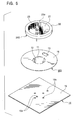
- Fig. 6 is a perspective exploded view of a composite antenna according to a second embodiment of the present invention.
- Fig. 7 is a perspective view of the composite antenna shown in Fig. 6.
- Fig. 8 is a top view of the composite antenna shown in Fig. 6.
- Fig. 9 is a sectional view taken on along the line IX-IX in Fig. 8.
- the composite antenna shown in Figs. 6 to 9 mainly includes a printed circuit board 14 having a plurality of insertion holes 10a in a plurality of positions, a plane antenna 100 for terrestrial waves which is held on the printed circuit board 14, and a patch antenna 200 for satellite waves which is held on the plane antenna 100.
- the plane antenna 100 mainly includes a circular metal plate 10 having an opening 11 in the center, four ground terminals 12 downwardly bent at the inner edge as a base end of the metal plate 10, a power-supply terminal 13 formed by cutting and pressing a portion of the metal plate 10 to bend downwardly, and a grounded conductor 15 such as copper foil which is provided on the almost entire top surface of a printed circuit board 14.
- a predetermined high frequency signal can be supplied to the power-supply terminal 13.
- Each ground terminal 12 and the power-supply terminal 13 are formed by performing blanking on portions of the metal plate 10 and subsequently bending the portions.
- the terminals 12 and 13, and the metal plate 10 are constituted by a single sheet of metal.
- the four ground terminals 12 are disposed at equal intervals, and each ground terminal 12 and the power-supply terminal 13 are formed having equal lengths.
- the printed circuit board 14 has, on its bottom surface, a land 18 to which the bottom ends of the ground terminals 12, which pass through insertion holes 10a, are soldered, and a land 19 to which the bottom end of the power-supply terminal 13, which passes through the insertion hole 10a, is soldered.
- the land 18 is in conduction with the ground conductor 15 on the top surface, and a power-supply line (internal conductor) of a coaxial cable 30 is soldered to the land 19. Since the terminals 12 and 13 are fixed to the printed circuit board 14, it is ensured that the metal plate 10 is supported in a stable posture by the printed circuit board 14, with a predetermined distance provided between the metal plate 10 and the ground conductor 15. The position of the power-supply terminal 13 formed on the metal plate 10 is determined by selecting an appropriate position in which their impedances match.
- the plane antenna 100 By appropriately setting the size of the metal plate 10 and the distance between the metal plate 10 and the ground conductor 15 so that the plane antenna 100 is excited in the TM01 mode which is a lowest resonant frequency mode, the plane antenna having the above structure emits nondirectional vertically-polarized radio waves in a plane in parallel with the metal plate 10.
- the plane antenna 100 can be functioned as a vertical-polarized-wave antenna for terrestrial waves in which reception sensitivities do not differ depending on azimuths.
- the metal plate 10 has a circular exterior shape, if it has a polygonal exterior shape, nondirectional characteristics of the plane antenna 100 cannot be greatly lost.
- a patch antenna 200 mainly includes a circular dielectric substrate 20, an almost circular patch electrode 21 provided on the top surface of the dielectric substrate 20, a ground terminal 22 provided on the almost entire bottom surface of the dielectric substrate 20, a power-supply pin 23 which is soldered to the patch electrode 21 and which passes through the dielectric substrate 20 and the opening 11.
- the power-supply pin 23 is supplied with a predetermined high frequency signal.
- the dielectric substrate 20 is concentrically mounted on the metal plate 10 in the plane antenna 100, with the bottom surface of the dielectric substrate 20 bonded to the metal plate 10 by a two-sided insulating tape 24.
- the patch electrode 21 is an emitting element having a microstrip structure, and has, in its periphery, cuts 21a (which may be projections) as degeneracy breaking elements in two symmetrical positions with reference to a point.
- the power-supply pin 23 is connected to the patch electrode 21 by selecting an appropriate power-supply point in which impedance matching occurs. Since the position of the power-supply point is close to the center of the patch electrode 21, it is above the opening 11 on the plane antenna 100.
- the power-supply pin 23 which leads downward from the power-supply point is in contact with the metal plate 10 and the terminals 12 and 13.
- the bottom end of the power-supply pin 23 passes through the insertion hole 23a and is soldered to a power-supply line (internal conductor) of a coaxial cable 31 below the printed circuit board 14.
- the patch antenna 200 By appropriately setting the patch electrode 21 and the cuts 21a and exciting the patch antenna 200 in the TM11 mode, the patch antenna 200 upwardly emits circularly polarized radio waves.
- the patch antenna 200 can be functioned as a circularly-polarized-wave antenna for satellite waves.
- a single point power supply method is employed which has a single power-supply point and in which, by laying degeneracy breaking elements such as the cuts 21a, two orthogonal modes having different resonant lengths have a phase difference of 90 degrees.
- the composite antenna according to the second embodiment can receive terrestrial waves by using the plane antenna 100 and can receive satellite waves by using the patch antenna 200.
- a structure in which the patch antenna 200 is stacked on the plane antenna 100 promotes reduction in size and thickness of the entire apparatus. Accordingly, the composite antenna is suitable for use as a small in-vehicle antenna that can receive both terrestrial waves and satellite waves.
- the composite antenna has a circumferentially uniform relative positional relationship between the metal plate 10 and the patch electrode 21. Thus, deterioration in nondirectional characteristics which is caused by the electromagnetic coupling between the plane antenna 100 and the patch antenna 200 is reduced. This can expect stable performance in which difference in reception sensitivity which is caused by an azimuth is reduced.
- the metal plate 10, the ground terminals 12, and the power-supply terminal 13 can be easily formed by performing blanking on portions of a sheet of metal and bending the portions.
- reduced numbers of components and assembly steps enable inexpensive production, and also assembly precision and mechanical strength can be easily ensured.
- the terminals 12 and 13 fixed to the printed circuit board 14 can stably support the metal plate 10 and the dielectric substrate 20, so that an inexpensive and highly reliable composite antenna can be obtained.
- the operation of connecting the ground terminals 12 and the power-supply terminal 13 in the plane antenna 100 to the lands 18 and 19, and the operation of connecting the power-supply pin 23 in the patch antenna 200 to the coaxial cable 31 are easily performed below the printed circuit board 14.
- Fig. 10 is a perspective view of a composite antenna according to a third embodiment of the present invention.
- the entirety of a patch antenna is denoted by reference numeral 250 and components corresponding to those shown in Fig. 7 are denoted by identical reference numerals.
- the composite antenna in Fig. 10 differs from the second embodiment in that the patch antenna 250 employs a two-point power-supply method and includes a 90-degree phase-difference circuit (not shown) on a printed circuit board 14.
- the patch antenna 250 the top surface of a dielectric substrate 26 is provided with a patch electrode 27, the patch electrode 27 has power-supply pins 28 and 29 soldered to two portions thereof, and the bottom ends of the power-supply pins 28 and 29 are connected to the 90-degree phase-difference circuit. This can excite the patch antenna 250 in two orthogonal modes having a phase difference of 90 degrees.
- the patch antenna 250 can be functioned as a circularly-polarized-wave antenna for satellite broadcasts similarly to the patch antenna 200.
- each of the second and third embodiments in the case of actually providing the composite antenna to a movable body such as an automobile, it is preferable to cover the composite antenna with a radome (not shown).
- a radome composed of dielectric material, adhesion of dust and impact of a flying object can be prevented without affecting antenna characteristics.
- the life of the composite antenna can be extended.
- a sheet of metal is used to form the metal plate 10, the ground terminals 12, and the power-supply terminal 13, the ground terminals 12 and the power-supply terminal 13 may be metal pins separate from the metal plate 10.
Landscapes
- Waveguide Aerials (AREA)
Applications Claiming Priority (4)
| Application Number | Priority Date | Filing Date | Title |
|---|---|---|---|
| JP2002202802 | 2002-07-11 | ||
| JP2002202838A JP2004048367A (ja) | 2002-07-11 | 2002-07-11 | 複合アンテナ |
| JP2002202802A JP2004048364A (ja) | 2002-07-11 | 2002-07-11 | 平板アンテナ |
| JP2002202838 | 2002-07-11 |
Publications (1)
| Publication Number | Publication Date |
|---|---|
| EP1381111A1 true EP1381111A1 (fr) | 2004-01-14 |
Family
ID=29738479
Family Applications (1)
| Application Number | Title | Priority Date | Filing Date |
|---|---|---|---|
| EP03254206A Ceased EP1381111A1 (fr) | 2002-07-11 | 2003-07-02 | Petite antenne plane et antenne composite utilisant cette antenne |
Country Status (2)
| Country | Link |
|---|---|
| US (1) | US20040021606A1 (fr) |
| EP (1) | EP1381111A1 (fr) |
Cited By (6)
| Publication number | Priority date | Publication date | Assignee | Title |
|---|---|---|---|---|
| EP1530254A1 (fr) * | 2003-11-10 | 2005-05-11 | Alps Electric Co., Ltd. | Antenne avec une plaque conductrice rayonnante miniaturisée |
| EP1531517A1 (fr) * | 2003-11-12 | 2005-05-18 | Alps Electric Co., Ltd. | Antenne haute fiabilité à polarisation circulaire en tole métallique |
| WO2014057239A1 (fr) * | 2012-10-10 | 2014-04-17 | Digital Barriers Services Ltd. | Antenne pour détecteur au sol non surveillé |
| CN109075437A (zh) * | 2016-05-10 | 2018-12-21 | 诺瓦特公司 | 使用具有图案化空腔的电介质基板的堆叠式贴片天线 |
| CN109216879A (zh) * | 2017-06-30 | 2019-01-15 | Gn 奥迪欧有限公司 | 用于耳机的天线结构 |
| CN114914682A (zh) * | 2022-07-11 | 2022-08-16 | 上海英内物联网科技股份有限公司 | 一种用于封闭金属腔体环境下的折线形微带近场天线 |
Families Citing this family (15)
| Publication number | Priority date | Publication date | Assignee | Title |
|---|---|---|---|---|
| JP2004165980A (ja) * | 2002-11-13 | 2004-06-10 | Alps Electric Co Ltd | パッチアンテナ |
| TWI264143B (en) * | 2004-05-12 | 2006-10-11 | Arcadyan Technology Corp | Inverted-F antenna having reinforced fixing structure |
| US7746283B2 (en) * | 2007-05-17 | 2010-06-29 | Laird Technologies, Inc. | Radio frequency identification (RFID) antenna assemblies with folded patch-antenna structures |
| US7796041B2 (en) * | 2008-01-18 | 2010-09-14 | Laird Technologies, Inc. | Planar distributed radio-frequency identification (RFID) antenna assemblies |
| CN102104190A (zh) * | 2009-12-21 | 2011-06-22 | 鸿富锦精密工业(深圳)有限公司 | 天线及其小型化方法 |
| JP2011171839A (ja) * | 2010-02-16 | 2011-09-01 | Toshiba Tec Corp | アンテナおよび携帯機器 |
| JP5048092B2 (ja) * | 2010-02-16 | 2012-10-17 | 東芝テック株式会社 | アンテナおよび携帯機器 |
| US8963793B2 (en) * | 2010-07-15 | 2015-02-24 | Cisco Technology, Inc. | Dual band antenna design |
| US10158167B2 (en) * | 2012-07-24 | 2018-12-18 | Novatel Inc. | Irridium/inmarsat and GNSS antenna system |
| US10056934B2 (en) * | 2015-01-07 | 2018-08-21 | Autodesk, Inc. | Dynamically configurable antennas |
| US9490540B1 (en) * | 2015-09-02 | 2016-11-08 | Hand Held Products, Inc. | Patch antenna |
| US10862198B2 (en) | 2017-03-14 | 2020-12-08 | R.A. Miller Industries, Inc. | Wideband, low profile, small area, circular polarized uhf antenna |
| JP6518285B2 (ja) * | 2017-05-01 | 2019-05-22 | 原田工業株式会社 | アンテナ装置 |
| WO2021000140A1 (fr) * | 2019-06-30 | 2021-01-07 | 瑞声声学科技(深圳)有限公司 | Oscillateur d'antenne et son procédé de préparation |
| EP4583309A1 (fr) * | 2023-11-30 | 2025-07-09 | Apple Inc. | Terminal de communication avec éléments rayonnants d'antenne entrelacés et autonomes |
Citations (5)
| Publication number | Priority date | Publication date | Assignee | Title |
|---|---|---|---|---|
| EP0362079A2 (fr) * | 1988-09-30 | 1990-04-04 | Sony Corporation | Antenne à microruban |
| US4994820A (en) * | 1988-12-16 | 1991-02-19 | Nissan Motor Co., Ltd. | Plane antenna |
| EP0490760A1 (fr) * | 1990-12-14 | 1992-06-17 | Thomson-Trt Defense | Antenne de type anneau, à fréquence centrale de fonctionnement réduite et véhicule équipé d'au moins une telle antenne |
| US5243353A (en) * | 1989-10-31 | 1993-09-07 | Mitsubishi Denki Kabushiki Kaisha | Circularly polarized broadband microstrip antenna |
| WO1997041619A1 (fr) * | 1996-04-26 | 1997-11-06 | Dorne & Margolin, Inc. | Combinaison d'antennes pour communications cellulaires et communications par systeme gps |
Family Cites Families (6)
| Publication number | Priority date | Publication date | Assignee | Title |
|---|---|---|---|---|
| US5019829A (en) * | 1989-02-08 | 1991-05-28 | Heckman Douglas E | Plug-in package for microwave integrated circuit having cover-mounted antenna |
| JP3308558B2 (ja) * | 1991-05-02 | 2002-07-29 | 富士通株式会社 | アンテナモジュール |
| JP3020777B2 (ja) * | 1993-07-23 | 2000-03-15 | 宏之 新井 | 二周波共用アンテナ |
| US6184834B1 (en) * | 1999-02-17 | 2001-02-06 | Ncr Corporation | Electronic price label antenna for electronic price labels of different sizes |
| DE60121507T2 (de) * | 2000-05-26 | 2006-12-07 | Matsushita Electric Industrial Co., Ltd., Kadoma | Antenne, Antennenanordnung und Funkgerät |
| JP2002374115A (ja) * | 2001-06-15 | 2002-12-26 | Nec Corp | アンテナ素子、アンテナ装置、無線通信装置 |
-
2003
- 2003-06-30 US US10/610,146 patent/US20040021606A1/en not_active Abandoned
- 2003-07-02 EP EP03254206A patent/EP1381111A1/fr not_active Ceased
Patent Citations (5)
| Publication number | Priority date | Publication date | Assignee | Title |
|---|---|---|---|---|
| EP0362079A2 (fr) * | 1988-09-30 | 1990-04-04 | Sony Corporation | Antenne à microruban |
| US4994820A (en) * | 1988-12-16 | 1991-02-19 | Nissan Motor Co., Ltd. | Plane antenna |
| US5243353A (en) * | 1989-10-31 | 1993-09-07 | Mitsubishi Denki Kabushiki Kaisha | Circularly polarized broadband microstrip antenna |
| EP0490760A1 (fr) * | 1990-12-14 | 1992-06-17 | Thomson-Trt Defense | Antenne de type anneau, à fréquence centrale de fonctionnement réduite et véhicule équipé d'au moins une telle antenne |
| WO1997041619A1 (fr) * | 1996-04-26 | 1997-11-06 | Dorne & Margolin, Inc. | Combinaison d'antennes pour communications cellulaires et communications par systeme gps |
Non-Patent Citations (1)
| Title |
|---|
| MASAYUKI NAKANO ET AL: "FEED CIRCUITS OF DOUBLE-LAYERED SELF-DIPLEXING ANTENNA FOR MOBILE SATELLITE COMMUNICATIONS", IEEE TRANSACTIONS ON ANTENNAS AND PROPAGATION, IEEE INC. NEW YORK, US, vol. 40, no. 10, 1 October 1992 (1992-10-01), pages 1269 - 1271, XP000336959, ISSN: 0018-926X * |
Cited By (12)
| Publication number | Priority date | Publication date | Assignee | Title |
|---|---|---|---|---|
| EP1530254A1 (fr) * | 2003-11-10 | 2005-05-11 | Alps Electric Co., Ltd. | Antenne avec une plaque conductrice rayonnante miniaturisée |
| US7046203B2 (en) | 2003-11-10 | 2006-05-16 | Alps Electric Co., Ltd. | Antenna device having miniaturized radiating conductor plate |
| EP1531517A1 (fr) * | 2003-11-12 | 2005-05-18 | Alps Electric Co., Ltd. | Antenne haute fiabilité à polarisation circulaire en tole métallique |
| US7075486B2 (en) | 2003-11-12 | 2006-07-11 | Alps Electric Co., Ltd. | Circularly polarized wave antenna made of sheet metal with high reliability |
| WO2014057239A1 (fr) * | 2012-10-10 | 2014-04-17 | Digital Barriers Services Ltd. | Antenne pour détecteur au sol non surveillé |
| US9692111B2 (en) | 2012-10-10 | 2017-06-27 | Digital Barriers Services Ltd. | Antenna for unattended ground sensor |
| RU2637393C2 (ru) * | 2012-10-10 | 2017-12-04 | Диджитал Бэриэрз Сервисез Лтд. | Антенна для сборки в составе автономного наземного блока обнаружения |
| CN109075437A (zh) * | 2016-05-10 | 2018-12-21 | 诺瓦特公司 | 使用具有图案化空腔的电介质基板的堆叠式贴片天线 |
| CN109216879A (zh) * | 2017-06-30 | 2019-01-15 | Gn 奥迪欧有限公司 | 用于耳机的天线结构 |
| CN109216879B (zh) * | 2017-06-30 | 2021-04-06 | Gn 奥迪欧有限公司 | 用于耳机的天线结构 |
| CN114914682A (zh) * | 2022-07-11 | 2022-08-16 | 上海英内物联网科技股份有限公司 | 一种用于封闭金属腔体环境下的折线形微带近场天线 |
| CN114914682B (zh) * | 2022-07-11 | 2022-11-01 | 上海英内物联网科技股份有限公司 | 一种用于封闭金属腔体环境下的折线形微带近场天线 |
Also Published As
| Publication number | Publication date |
|---|---|
| US20040021606A1 (en) | 2004-02-05 |
Similar Documents
| Publication | Publication Date | Title |
|---|---|---|
| EP1381111A1 (fr) | Petite antenne plane et antenne composite utilisant cette antenne | |
| EP1478051B1 (fr) | Système d'antennes combinées intégrant une antenne à polarisation circulaire et une antenne à polarisation verticale | |
| JP4298173B2 (ja) | 円偏波された誘電体共振器アンテナ | |
| US6292141B1 (en) | Dielectric-patch resonator antenna | |
| US8810467B2 (en) | Multi-band dipole antennas | |
| US6344833B1 (en) | Adjusted directivity dielectric resonator antenna | |
| US9065166B2 (en) | Multi-band planar inverted-F (PIFA) antennas and systems with improved isolation | |
| KR100771775B1 (ko) | 수직배열 내장형 안테나 | |
| US7551145B2 (en) | Slot antenna | |
| CN110637394B (zh) | 车载用天线装置 | |
| CN100365866C (zh) | 包括馈线组织体的补件偶极子阵列天线及相关方法 | |
| WO2006032305A1 (fr) | Antennes planes pour des applications satellites mobiles | |
| US7079078B2 (en) | Patch antenna apparatus preferable for receiving ground wave and signal wave from low elevation angle satellite | |
| JP2005508099A (ja) | 移動機器用のマルチバンドアンテナ | |
| US9728845B2 (en) | Dual antenna structure having circular polarisation characteristics | |
| US20240072444A1 (en) | Multiband patch antenna | |
| JP2001168637A (ja) | クロスダイポールアンテナ | |
| JPH07303005A (ja) | 車両用アンテナ装置 | |
| JP2004048369A (ja) | 複合アンテナ | |
| US6727858B2 (en) | Circularly polarized wave antenna suitable for miniaturization | |
| JP2004048367A (ja) | 複合アンテナ | |
| JP2003309428A (ja) | 円偏波アンテナ | |
| JP2004312546A (ja) | パッチアンテナ | |
| JP2003110355A (ja) | 複合アンテナ | |
| JP2003234614A (ja) | 誘電体アンテナ |
Legal Events
| Date | Code | Title | Description |
|---|---|---|---|
| PUAI | Public reference made under article 153(3) epc to a published international application that has entered the european phase |
Free format text: ORIGINAL CODE: 0009012 |
|
| AK | Designated contracting states |
Kind code of ref document: A1 Designated state(s): AT BE BG CH CY CZ DE DK EE ES FI FR GB GR HU IE IT LI LU MC NL PT RO SE SI SK TR |
|
| AX | Request for extension of the european patent |
Extension state: AL LT LV MK |
|
| 17P | Request for examination filed |
Effective date: 20040105 |
|
| 17Q | First examination report despatched |
Effective date: 20040506 |
|
| AKX | Designation fees paid |
Designated state(s): DE FR GB SE |
|
| STAA | Information on the status of an ep patent application or granted ep patent |
Free format text: STATUS: THE APPLICATION HAS BEEN REFUSED |
|
| 18R | Application refused |
Effective date: 20050927 |