EP1383119A2 - Optisches Abtastgerät - Google Patents
Optisches Abtastgerät Download PDFInfo
- Publication number
- EP1383119A2 EP1383119A2 EP03100804A EP03100804A EP1383119A2 EP 1383119 A2 EP1383119 A2 EP 1383119A2 EP 03100804 A EP03100804 A EP 03100804A EP 03100804 A EP03100804 A EP 03100804A EP 1383119 A2 EP1383119 A2 EP 1383119A2
- Authority
- EP
- European Patent Office
- Prior art keywords
- optical
- light
- reading light
- pickup apparatus
- tangential direction
- Prior art date
- Legal status (The legal status is an assumption and is not a legal conclusion. Google has not performed a legal analysis and makes no representation as to the accuracy of the status listed.)
- Withdrawn
Links
Images




Classifications
-
- G—PHYSICS
- G11—INFORMATION STORAGE
- G11B—INFORMATION STORAGE BASED ON RELATIVE MOVEMENT BETWEEN RECORD CARRIER AND TRANSDUCER
- G11B7/00—Recording or reproducing by optical means, e.g. recording using a thermal beam of optical radiation by modifying optical properties or the physical structure, reproducing using an optical beam at lower power by sensing optical properties; Record carriers therefor
- G11B7/12—Heads, e.g. forming of the optical beam spot or modulation of the optical beam
- G11B7/135—Means for guiding the beam from the source to the record carrier or from the record carrier to the detector
- G11B7/1372—Lenses
- G11B7/1376—Collimator lenses
-
- G—PHYSICS
- G11—INFORMATION STORAGE
- G11B—INFORMATION STORAGE BASED ON RELATIVE MOVEMENT BETWEEN RECORD CARRIER AND TRANSDUCER
- G11B19/00—Driving, starting, stopping record carriers not specifically of filamentary or web form, or of supports therefor; Control thereof; Control of operating function ; Driving both disc and head
- G11B19/02—Control of operating function, e.g. switching from recording to reproducing
- G11B19/12—Control of operating function, e.g. switching from recording to reproducing by sensing distinguishing features of or on records, e.g. diameter end mark
-
- G—PHYSICS
- G11—INFORMATION STORAGE
- G11B—INFORMATION STORAGE BASED ON RELATIVE MOVEMENT BETWEEN RECORD CARRIER AND TRANSDUCER
- G11B19/00—Driving, starting, stopping record carriers not specifically of filamentary or web form, or of supports therefor; Control thereof; Control of operating function ; Driving both disc and head
- G11B19/02—Control of operating function, e.g. switching from recording to reproducing
- G11B19/12—Control of operating function, e.g. switching from recording to reproducing by sensing distinguishing features of or on records, e.g. diameter end mark
- G11B19/128—Control of operating function, e.g. switching from recording to reproducing by sensing distinguishing features of or on records, e.g. diameter end mark involving the detection of track pitch or recording density
-
- G—PHYSICS
- G11—INFORMATION STORAGE
- G11B—INFORMATION STORAGE BASED ON RELATIVE MOVEMENT BETWEEN RECORD CARRIER AND TRANSDUCER
- G11B7/00—Recording or reproducing by optical means, e.g. recording using a thermal beam of optical radiation by modifying optical properties or the physical structure, reproducing using an optical beam at lower power by sensing optical properties; Record carriers therefor
- G11B7/12—Heads, e.g. forming of the optical beam spot or modulation of the optical beam
- G11B7/125—Optical beam sources therefor, e.g. laser control circuitry specially adapted for optical storage devices; Modulators, e.g. means for controlling the size or intensity of optical spots or optical traces
- G11B7/127—Lasers; Multiple laser arrays
-
- G—PHYSICS
- G11—INFORMATION STORAGE
- G11B—INFORMATION STORAGE BASED ON RELATIVE MOVEMENT BETWEEN RECORD CARRIER AND TRANSDUCER
- G11B7/00—Recording or reproducing by optical means, e.g. recording using a thermal beam of optical radiation by modifying optical properties or the physical structure, reproducing using an optical beam at lower power by sensing optical properties; Record carriers therefor
- G11B7/12—Heads, e.g. forming of the optical beam spot or modulation of the optical beam
- G11B7/125—Optical beam sources therefor, e.g. laser control circuitry specially adapted for optical storage devices; Modulators, e.g. means for controlling the size or intensity of optical spots or optical traces
- G11B7/127—Lasers; Multiple laser arrays
- G11B7/1275—Two or more lasers having different wavelengths
-
- G—PHYSICS
- G11—INFORMATION STORAGE
- G11B—INFORMATION STORAGE BASED ON RELATIVE MOVEMENT BETWEEN RECORD CARRIER AND TRANSDUCER
- G11B7/00—Recording or reproducing by optical means, e.g. recording using a thermal beam of optical radiation by modifying optical properties or the physical structure, reproducing using an optical beam at lower power by sensing optical properties; Record carriers therefor
- G11B7/12—Heads, e.g. forming of the optical beam spot or modulation of the optical beam
- G11B7/135—Means for guiding the beam from the source to the record carrier or from the record carrier to the detector
- G11B7/1353—Diffractive elements, e.g. holograms or gratings
-
- G—PHYSICS
- G11—INFORMATION STORAGE
- G11B—INFORMATION STORAGE BASED ON RELATIVE MOVEMENT BETWEEN RECORD CARRIER AND TRANSDUCER
- G11B7/00—Recording or reproducing by optical means, e.g. recording using a thermal beam of optical radiation by modifying optical properties or the physical structure, reproducing using an optical beam at lower power by sensing optical properties; Record carriers therefor
- G11B7/12—Heads, e.g. forming of the optical beam spot or modulation of the optical beam
- G11B7/135—Means for guiding the beam from the source to the record carrier or from the record carrier to the detector
- G11B7/1365—Separate or integrated refractive elements, e.g. wave plates
-
- G—PHYSICS
- G11—INFORMATION STORAGE
- G11B—INFORMATION STORAGE BASED ON RELATIVE MOVEMENT BETWEEN RECORD CARRIER AND TRANSDUCER
- G11B7/00—Recording or reproducing by optical means, e.g. recording using a thermal beam of optical radiation by modifying optical properties or the physical structure, reproducing using an optical beam at lower power by sensing optical properties; Record carriers therefor
- G11B7/12—Heads, e.g. forming of the optical beam spot or modulation of the optical beam
- G11B7/135—Means for guiding the beam from the source to the record carrier or from the record carrier to the detector
- G11B7/1365—Separate or integrated refractive elements, e.g. wave plates
- G11B7/1369—Active plates, e.g. liquid crystal panels or electrostrictive elements
-
- G—PHYSICS
- G11—INFORMATION STORAGE
- G11B—INFORMATION STORAGE BASED ON RELATIVE MOVEMENT BETWEEN RECORD CARRIER AND TRANSDUCER
- G11B7/00—Recording or reproducing by optical means, e.g. recording using a thermal beam of optical radiation by modifying optical properties or the physical structure, reproducing using an optical beam at lower power by sensing optical properties; Record carriers therefor
- G11B7/12—Heads, e.g. forming of the optical beam spot or modulation of the optical beam
- G11B7/135—Means for guiding the beam from the source to the record carrier or from the record carrier to the detector
- G11B7/1372—Lenses
- G11B7/1378—Separate aberration correction lenses; Cylindrical lenses to generate astigmatism; Beam expanders
-
- G—PHYSICS
- G11—INFORMATION STORAGE
- G11B—INFORMATION STORAGE BASED ON RELATIVE MOVEMENT BETWEEN RECORD CARRIER AND TRANSDUCER
- G11B7/00—Recording or reproducing by optical means, e.g. recording using a thermal beam of optical radiation by modifying optical properties or the physical structure, reproducing using an optical beam at lower power by sensing optical properties; Record carriers therefor
- G11B7/12—Heads, e.g. forming of the optical beam spot or modulation of the optical beam
- G11B7/135—Means for guiding the beam from the source to the record carrier or from the record carrier to the detector
- G11B7/1381—Non-lens elements for altering the properties of the beam, e.g. knife edges, slits, filters or stops
-
- G—PHYSICS
- G11—INFORMATION STORAGE
- G11B—INFORMATION STORAGE BASED ON RELATIVE MOVEMENT BETWEEN RECORD CARRIER AND TRANSDUCER
- G11B7/00—Recording or reproducing by optical means, e.g. recording using a thermal beam of optical radiation by modifying optical properties or the physical structure, reproducing using an optical beam at lower power by sensing optical properties; Record carriers therefor
- G11B7/12—Heads, e.g. forming of the optical beam spot or modulation of the optical beam
- G11B7/135—Means for guiding the beam from the source to the record carrier or from the record carrier to the detector
- G11B7/139—Numerical aperture control means
-
- G—PHYSICS
- G11—INFORMATION STORAGE
- G11B—INFORMATION STORAGE BASED ON RELATIVE MOVEMENT BETWEEN RECORD CARRIER AND TRANSDUCER
- G11B7/00—Recording or reproducing by optical means, e.g. recording using a thermal beam of optical radiation by modifying optical properties or the physical structure, reproducing using an optical beam at lower power by sensing optical properties; Record carriers therefor
- G11B7/12—Heads, e.g. forming of the optical beam spot or modulation of the optical beam
- G11B7/135—Means for guiding the beam from the source to the record carrier or from the record carrier to the detector
- G11B7/1392—Means for controlling the beam wavefront, e.g. for correction of aberration
- G11B7/13925—Means for controlling the beam wavefront, e.g. for correction of aberration active, e.g. controlled by electrical or mechanical means
-
- G—PHYSICS
- G11—INFORMATION STORAGE
- G11B—INFORMATION STORAGE BASED ON RELATIVE MOVEMENT BETWEEN RECORD CARRIER AND TRANSDUCER
- G11B7/00—Recording or reproducing by optical means, e.g. recording using a thermal beam of optical radiation by modifying optical properties or the physical structure, reproducing using an optical beam at lower power by sensing optical properties; Record carriers therefor
- G11B7/12—Heads, e.g. forming of the optical beam spot or modulation of the optical beam
- G11B7/135—Means for guiding the beam from the source to the record carrier or from the record carrier to the detector
- G11B7/1398—Means for shaping the cross-section of the beam, e.g. into circular or elliptical cross-section
-
- G—PHYSICS
- G11—INFORMATION STORAGE
- G11B—INFORMATION STORAGE BASED ON RELATIVE MOVEMENT BETWEEN RECORD CARRIER AND TRANSDUCER
- G11B7/00—Recording or reproducing by optical means, e.g. recording using a thermal beam of optical radiation by modifying optical properties or the physical structure, reproducing using an optical beam at lower power by sensing optical properties; Record carriers therefor
- G11B2007/0003—Recording, reproducing or erasing systems characterised by the structure or type of the carrier
- G11B2007/0006—Recording, reproducing or erasing systems characterised by the structure or type of the carrier adapted for scanning different types of carrier, e.g. CD & DVD
-
- G—PHYSICS
- G11—INFORMATION STORAGE
- G11B—INFORMATION STORAGE BASED ON RELATIVE MOVEMENT BETWEEN RECORD CARRIER AND TRANSDUCER
- G11B7/00—Recording or reproducing by optical means, e.g. recording using a thermal beam of optical radiation by modifying optical properties or the physical structure, reproducing using an optical beam at lower power by sensing optical properties; Record carriers therefor
- G11B7/12—Heads, e.g. forming of the optical beam spot or modulation of the optical beam
- G11B7/135—Means for guiding the beam from the source to the record carrier or from the record carrier to the detector
- G11B7/1372—Lenses
- G11B2007/13727—Compound lenses, i.e. two or more lenses co-operating to perform a function, e.g. compound objective lens including a solid immersion lens, positive and negative lenses either bonded together or with adjustable spacing
Definitions
- the present invention generally relates to an optical pickup apparatus for identifying the type of optical record medium used for the optical pickup apparatus.
- a multi-disc player which can reproduce a CD (Compact Disc) and a LD (Laser vision Disc) etc., as a reproducing apparatus able to reproduce a plurality of types of optical record media.
- CD Compact Disc
- LD Laser vision Disc
- a mechanical switch is provided so as to identify the type of the loaded optical disc on the basis of the fact that this mechanical switch is pressed or not by the loaded optical disc.
- an optical detection device such as a light sensor is equipped to detect the existence and non-existence of the reflection light reflected by the loaded optical disc.
- one optical pickup apparatus commonly for a plurality of optical discs of various types.
- the thickness of the protection layer (substrate) is far off from the optimum thickness set for each of the optical pickup apparatus, a spherical aberration is generated in the focussed light beam as the reading light beam at the information record plane of the optical disc, which is another serious problem to perform a precise reproduction operation.
- the spherical aberration W 40 is expressed by a following expression (1).
- W 40 ⁇ (n 2 -1)/8n 3 ⁇ * ⁇ d*(NA 4 / ⁇ )
- the above mentioned mechanical or optical identification apparatus for identifying the type of the loaded optical disc cannot identify the type of the loaded optical disc, if the thicknesses and refraction coefficients of the optical discs are substantially same to each other but only the distances from the surfaces of the protection layers to the information record planes are different from each other. In this case, a complicated identifying operation such as a comparison of record formats etc., will be necessary.
- those identification apparatuses cannot differentiate a first optical disc of both sides recording type produced by bonding two discs each of which has a protection layer with 0.6 mm thickness, from a second optical disc of one side recording type, which has an external diameter same as the first optical disc and which has a protection layer with 1.2 mm thickness, which is the problem.
- the spot diameter of the reading light beam is set to be a value optimum for the size of the information pit of the optical record medium to be reproduced.
- the spot diameter R of the reading light beam is proportional to the numerical aperture NA of the objective lens and the wavelength ⁇ of the reading light beam. Namely, the spot diameter satisfies a following expression (2). R ⁇ /NA
- the numerical aperture NA of the objective lens is increased assuming that the wavelength ⁇ of the reading light beam is constant.
- the numerical aperture NA of the objective lens has a peculiar value for each objective lens.
- the optical pickup apparatus which is adjusted to be optimum with respect to a first information pit having a certain size, is not suitable for a second information pit having a size different from that of the first information pit. Therefore, the distortion will be generated in the reproduction signal if this optical pickup apparatus is used with respect to an optical record medium formed with the second information pit, which is a problem in this case.
- an optical pickup apparatus for an information reproducing apparatus adapted to reproduce one of at least first and second type optical record media which is loaded on said information reproducing apparatus, said first and second type optical record media having information pits, which sizes are different from each other, and record tracks, on which said information pits are arranged respectively, characterized in that said optical pickup apparatus comprises:
- the reading light is emitted by the light emission device. Then, the emitted reading light is focussed onto the information record plane of the loaded optical record medium by the objective lens, such that the light intensity distribution in the tangential direction of the focussed reading light is optimum with respect to the first type of optical record medium.
- the optimum light intensity distribution in the tangential direction can be obtained without the necessity of the correction device for correcting the light intensity distribution.
- the second type optical record medium is loaded, the light intensity distribution in the tangential direction of the focussed reading light due to the difference in the distances from the surfaces to the information record planes between the first and second type optical reading media is corrected by the correction device.
- the optimum light intensity distribution can be obtained by virtue of the correction device for correcting the light intensity distribution as if the numerical aperture of the objective lens were adjusted to the size of the information pit of the second type optical record medium.
- the reflection light of the focussed reading light from the information record plane of either one of the first and second optical record media is received by the light receiving device. Consequently, the optimum reproduction can be performed with respect to either one of the first and second type optical record media, according to the optical pickup apparatus of the present invention.
- the correction device is provided with: a correction element for correcting the light intensity distribution when the correction element is placed in an optical path of the emitted reading light between the light emission device and the objective lens; and moving a device for selectively moving the correction element into the optical path and out of the optical path in accordance with a disc identification signal, which is inputted from the external and indicates the type of the loaded one of the first and second optical record media.
- the light intensity distribution is corrected by the correction element when the second optical record medium is loaded, since the correction element is placed in the optical path at this event by virtue of the moving device which moves the correction element in accordance with the disc identification signal.
- the optimum reproduction operation can be performed.
- the correction device is provided with a slit plate having a light cutting plate formed with a slit for shadowing both edge portions of the emitted reading light in the tangential direction by the light cutting plate and for transmitting a central portion of the emitted reading light in the tangential direction through the slit.
- the correction device is provided with a glass filter having a glass plate and coating layers formed on both edge portions of a surface of the glass plate such that both edge portions of the emitted reading light in the tangential direction are shadowed by the coating layers and that a central portion of the emitted reading light in the tangential direction is transmitted through a portion of the glass plate between the coating layers.
- the correction device is provided with a glass plate and gratings formed on both edge portions of a surface of the glass plate such that both edge portions of the emitted reading light in the tangential direction are transmitted through the gratings and that a central portion of the emitted reading light in the tangential direction is transmitted through a portion of the glass plate between the gratings.
- the correction device is provided with: a liquid crystal shutter which is fixed in an optical path between the light emission device and the objective lens for shutting both edge portions of the emitted reading light in the tangential direction such that a central portion of the emitted reading light in the tangential direction is transmitted therethrough when the liquid crystal shutter is electrically driven to shut; and a liquid crystal driving device for electrically driving the liquid crystal shutter when the second type optical record medium is loaded.
- the correction device is disposed on one of a grating, a half mirror, a collimator lens and the objective lens which are arranged in an optical path from the light emission device to the loaded one of the first and second optical record media.
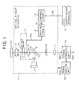
- FIG. 1 shows a construction of an optical pickup apparatus as a first example, which is equipped in an optical disc player.
- an optical pickup apparatus 1 is provided with: a semiconductor laser diode 2 for emitting a reading light; a grating 3 for separating the reading light into three beams; a half mirror 4 for reflecting and guiding the reading light from the laser diode 2 toward the side of an objective lens 9, and transmitting the reading light from the side of the objective lens 9 toward a light receiving element 11; a collimator lens 5 for converting the reading light which is a diffused light to a collimated light; a correcting element 6 for correcting the spherical aberration consisting of a spherical lens, a Fresnel lens, etc.; a driving mechanism 7 for moving the correction element 6; a driving circuit 8 for driving the driving mechanism 7 to move the correction element 6 into the optical path and move the correction element 6 out of the optical path, by outputting a driving control signal Sdr on the basis of a control signal Sc to the driving mechanism 7; the objective lens 9 for condensing and focussing the reading light onto an optical
- the optical disc player is provided with a disc identifying sensor 12, as one example of a disc identification apparatus, for identifying the type of the optical disc 101 and outputting a disc identification signal Sd indicating the identified type of the optical disc 101.
- the optical pickup apparatus 1 is further provided with a control circuit 13 for generating the control signal Sc for controlling the moving in and out operation of the correction element 6 on the basis of the disc identification signal Sd.
- the optical disc player is further provided with: a signal process unit 14 for performing a predetermined signal process of the detection signal Sdet from the light receiving element 11, and a servo control unit 15 for performing servo controls such a focus servo control, a tracking servo control, a spindle servo control, etc., by generating servo control signals Sser on the basis of the signal processed by the signal process unit 14.
- the three lights separated by the grating 3 are applied onto one record track of the optical disc 101 to form three light spots arranged along one record track and slightly spaced from each other so as to allow the optical pickup apparatus 1 to use one of the reflection lights from those three light spots which is in the best optical condition among the three reflection lights.
- the disc identifying sensor 12 is provided with: a low pass filter 12A for passing only a low frequency component of the electric current flowing through a focus coil, which drives the objective lens 9 in the direction of focussing, and outputting it as a low frequency component signal having a voltage Vdc; and a comparator 12B for comparing the voltage Vdc of the low frequency component signal with a standard voltage Vref, and generating the disc identification signal Sd based on the result of the comparison.
- the voltage Vdc of the low frequency component signal corresponding to the protection layer thickness of 0.9 mm is set as the standard voltage Vref in the disc identifying sensor 12, for example.
- a stroke (driving distance) d of the objective lens 9 is substantially proportional to "t/n" in case that the incident angle of the light beam is relatively small, wherein t represents the thickness of the protection layer.
- the disc identifying sensor 12 outputs the disc identification signal Sd, which indicates that the identified disc type is the CD, if the voltage Vmdc obtained as the voltage Vdc of the low frequency component signal exceeds the standard voltage Vref, and outputs the disc identification signal Sd, which indicates that the identified disc type is the DVD if the voltage Vmdc does not exceeds the standard voltage Vref.
- the optical pickup apparatus 1 closes the focus servo to get the reading light focussed on the information record plane of the optical disc 101.
- the low pass filter 12A passes only the low frequency component of the voltage signal corresponding to the electric current flowing through the focus coil for driving the objective lens 9 in the focussing direction, and outputs it as the low frequency component signal having the voltage Vdcto the comparator 12B in FIG. 2A.
- the comparator 12B compares the voltage Vdc of the low frequency component signal with the standard voltage Vref and outputs the disc identification signal Sd corresponding to the identified type of the optical disc 101, which is loaded on the optical disc player in FIG. 2A.
- the disc identifying sensor 12 if the voltage Vmdc obtained as the voltage Vdc of the low frequency component signal exceeds the standard voltage Vref, the disc identifying sensor 12 outputs the disc identification signal Sd, which indicates that the identified disc type is the CD, to the control circuit 13. If the voltage Vmdc does not exceeds the standard voltage Vref, the disc identifying sensor 12 outputs the disc identification signal Sd, which indicates that the identified disc type is the DVD, to the control circuit 13.
- control circuit 13 outputs the control signal Sc to the driving circuit 8 to control the moving in and out operation for the correction element 6 on the basis of the disc identification signal Sd in FIG. 1.
- the driving circuit 8 outputs the driving control signal Sdr to the driving mechanism 7 on the basis of the control signal Sc, so as to move the correction element 6 into or out of the optical path in accordance with the disc identification signal Sd.
- the optical system of the optical pickup apparatus 1 is set to be suitable for the CD when the correction element 6 is not in the optical path.
- the correction element 6 is not moved if it is not in the optical path, and is moved out of the optical path if it is in the optical path, as shown in FIG. 3.
- the correction element 6 is moved into the optical path if it is in the optical path, and is not moved out if it is already in the optical path.
- the type of the loaded optical disc is detected just by the difference in the thickness of the protection layer, and the optimum aberration correction is performed for the identified type of the optical disc, so that the optimum reproduction operation for the loaded optical disc can be easily performed.
- the explanation has been made for the case of identifying two types of the optical discs which protection layer thicknesses are different from each other (i.e. the CD and the DVD).
- the optical pickup apparatus 1 it is possible to construct the optical pickup apparatus 1 such that a plurality of standard voltages may be set for the comparator 12B, more than two types of the optical discs may be identified and a plurality of correction elements are exchanged in accordance with the identified types of the optical discs.
- FIG. 4 shows a construction of an optical pickup apparatus as a second example, which is equipped in an optical disc player.
- constitutional elements same as those in the first example of FIG. 1 carry the same reference numerals and the explanation thereof are omitted.
- an optical pickup apparatus 60 is different from that of the first example of FIG. 1 in that a slit plate 61 for correcting a light intensity distribution in the tangential direction of the record track i.e. the disc rotation direction of the optical disc 101 is provided in place of the correction element 6 for correcting the spherical aberration in the first example.
- the slit plate 61 is driven by the driving mechanism 7 to move into and out of the optical path.
- Other constitutional elements of the second example are the same as those of the first example.
- the optical pickup apparatus 60 closes the focus servo to get the reading light focussed on the information record plane of the optical disc 101.
- the low pass filter 12A passes only the low frequency component of the voltage signal corresponding to the electric current flowing through the focus coil for driving the objective lens 9 in the focussing direction, and outputs it as the low frequency component signal having the voltage Vdc to the comparator 12B in FIG. 2A.
- the comparator 12B compares the voltage Vdc of the low frequency component signal with the standard voltage Vref and outputs the disc identification signal Sd corresponding to the identified type of the optical disc 101, which is loaded on the optical disc player in FIG. 2A.
- the DVD is constructed to have a record track pitch smaller than that of the CD, and also have an information pit size smaller than that of the CD, so as to improve the information record density, and that the numerical aperture of the objective lens 9 is set to be optimum for the reproduction of the DVD.
- control circuit 13 outputs the control signal Sc to the driving circuit 8 to control the moving in and out operation for the slit plate 61 on the basis of the disc identification signal Sd.
- the driving circuit 8 outputs the driving control signal Sdr to the driving mechanism 7 on the basis of the control signal Sc, so as to move the slit plate 61 into and out of the optical path in accordance with the disc identification signal Sd.
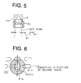
- the slit plat 61 is moved into the optical path if the slit plate 61 is not in the optical path, and is not moved but remains as it is if the slit plate 61 is already in the optical path as shown in FIG. 5.
- the objective lens 9 is actuated in the focussing direction by an actuator movable member 9a, and the slit plate 61 prescribes the width of the reading light incident to the objective lens 9 by the plate portion around the slit.
- the both edge portions of the pupil of the reading light beam, which is applied onto the optical disc 101, in the tangential direction of the record track, is shadowed by the slit plate 61 as indicated by a shaded area 61a on the optical disc 101.
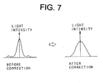
- the light intensity distribution in the tangential direction of the record track upon reproducing the CD is corrected as shown in FIG. 7.
- the reproduction signal after correction can be obtained by the reflection light from an information pit P, such that the distortion which would exists without the slit plate 61 is certainly corrected by the slit plate 61, according to the second example.
- the slit plate 61 is not moved but remains as it is if the slit plate 61 is not in the optical path and is moved out of the optical path 61 if the slit plate 61 is in the optical path.
- the light intensity distribution correction optimum for each size of the information pit of the loaded optical disc for each size of the information pit of the loaded optical disc is performed, so that the effect, which is substantially same as the case of correcting the numerical aperture NA of the objective lens, can be achieved.
- the optimum reproduction operation for the loaded optical disc can be easily performed.
- the explanation has been made for the case of reproducing two types of the optical discs which protection layer thickness are different from each other (i.e. the CD and the DVD).
- the optical pickup apparatus 60 such that a plurality of standard voltages are set to the comparator 12B of the disc identifying sensor 12, more than two types of the optical discs may be identified and a plurality of slit plates are exchanged in accordance with the identified types of the optical discs to perform the reproduction operation optimum for each optical disc.
- the slit plate 61 is used for correcting the light intensity distribution.
- a glass filter 71 shown in FIG. 9 for correcting the light intensity distribution is provided in place of the slit plate 61 in the construction shown in FIG. 4.
- the glass filter 71 is constructed such that a coating layer is applied to both edge portions on a surface of a glass substrate so as to decrease the light transmissivity of the glass substrate at the edge portions thereof in the tangential direction of the record track.
- the construction of the third example is the same as the second example.
- the light intensity distribution correction optimum for each size of the information pit of the loaded optical disc is performed, so that the effect, which is substantially same as the case of correcting the numerical aperture NA of the objective lens, can be achieved.
- the optimum reproduction operation for the loaded optical disc can be easily performed in the same manner as the second example.
- the glass filter 71 is used in place of the slit plate 61 in the construction of FIG. 4.
- a correction element 81 shown in FIG. 10 having gratings for correcting the light intensity distribution is used in place of the slit plate 61 of FIG. 4.
- the correction element 81 is constructed such that the gratings are provided at both edge portions of a glass substrate in the tangential direction of the record track of the optical disc 101.
- the grating direction of each grating of the correction element 81 is perpendicular to the tangential direction of the record track.
- the construction of the fourth embodiment is the same as the second example.
- the intensity of the zero order light beam, which has passed through each grating at the edge portions, is lower than that of the light beam, which has passed through a central portion of the correction element 81. Accordingly, the effect, which is substantially same as the case of correcting the numerical aperture NA of the objective lens, can be achieved. Thus, the optimum reproduction operation for the loaded disc can be easily performed in the same manner as the second example.
- the grating direction of each grating of the correction element 81 is perpendicular to the tangential direction of the record track of the optical disc 101.
- the grating direction of each grating of a correction element 91 is parallel to the tangential direction of the record track as shown in FIG. 11.
- the construction of the correction element 91 in the fifth example is the same as the correction element 81 in the fourth example.
- the grating direction for this kind of correction element 81 or 91 can be freely designed.
- an optical pickup apparatus 100 as a sixth example is constructed such that a correction element consisting of a liquid crystal shutter 110, which light transmissive amount can be electronically controlled by a shutter driving circuit 111 is fixed in the optical path, as shown in FIG. 12.
- a correction element consisting of a liquid crystal shutter 110, which light transmissive amount can be electronically controlled by a shutter driving circuit 111 is fixed in the optical path, as shown in FIG. 12.
- constitutional elements same as those in the second example of FIG. 4 carry the same reference numerals and the explanation thereof are omitted.
- the liquid crystal shutter 110 shuts both edge portions of the emitted reading light in the tangential direction of the record track such that a central portion of the emitted reading light in the tangential direction is transmitted through the liquid crystal shutter 110 when the liquid crystal shutter 110 is electrically driven by a shutter driving circuit 111 to shut.
- the shutter driving circuit 111 electrically drives the liquid crystal shutter 110 to shut in accordance with the disc identification signal Sd.
- the construction of the optical pickup apparatus 100 can be made simplified and the size of the optical pickup apparatus 100 can be made small.
- the correction of the light intensity distribution is performed by a separate optical element exclusive for correcting the light intensity distribution i.e. the slit plate, the glass filter, the correction element having the grating and the correction element electrically functioning as the correction element.
- an optical pickup apparatus 200 as a seventh example is constructed such that a separate correction element does not exist. Instead, by applying the coating layer or by forming the gratings on one of the optical elements disposed in the optical path between the laser diode 2 and the optical disc 101 i.e. the grating 3', the half mirror 4', the collimator lens 5' and the objective lens 9', the correction element for correcting the light intensity distribution is formed in one body with this one of the optical elements.
- the constitutional elements same as those in the second example of FIG. 4 carry the same reference numerals and the explanation thereof are omitted.
- the optical element (the grating 3', the half mirror 4' the collimator lens 5' or the objective lens 9') formed in one body with the correction element is adapted to be exchanged, or electrically controlled so as to change the light transmissive property in the tangential direction of the record track in accordance with the identified type of the loaded optical disc 101.
- the construction of the optical pickup apparatus 200 can be made simplified and the size of the optical pickup apparatus 200 can be made small.
Landscapes
- Physics & Mathematics (AREA)
- Optics & Photonics (AREA)
- Chemical & Material Sciences (AREA)
- Crystallography & Structural Chemistry (AREA)
- Optical Head (AREA)
- Optical Recording Or Reproduction (AREA)
Applications Claiming Priority (6)
| Application Number | Priority Date | Filing Date | Title |
|---|---|---|---|
| JP7016295A JPH08212578A (ja) | 1995-02-02 | 1995-02-02 | 光ピックアップ装置 |
| JP1629795 | 1995-02-02 | ||
| JP1629795A JP3599399B2 (ja) | 1995-02-02 | 1995-02-02 | 光ピックアップ装置及び光記録媒体判別装置 |
| JP1629595 | 1995-02-02 | ||
| EP96300591A EP0725395B1 (de) | 1995-02-02 | 1996-01-29 | Optisches Abtastgerät und Identifizierungsgerät zum Identifizieren des Typs eines optischen Aufzeichnungsmediums |
| EP01304711A EP1150281B1 (de) | 1995-02-02 | 1996-01-29 | Optisches Abtastgerät und Identifizierungsgerät zum Identifizieren des Typs eines optischen Aufzeichnungsmediums |
Related Parent Applications (1)
| Application Number | Title | Priority Date | Filing Date |
|---|---|---|---|
| EP01304711A Division EP1150281B1 (de) | 1995-02-02 | 1996-01-29 | Optisches Abtastgerät und Identifizierungsgerät zum Identifizieren des Typs eines optischen Aufzeichnungsmediums |
Publications (2)
| Publication Number | Publication Date |
|---|---|
| EP1383119A2 true EP1383119A2 (de) | 2004-01-21 |
| EP1383119A3 EP1383119A3 (de) | 2005-01-19 |
Family
ID=26352602
Family Applications (3)
| Application Number | Title | Priority Date | Filing Date |
|---|---|---|---|
| EP01304711A Expired - Lifetime EP1150281B1 (de) | 1995-02-02 | 1996-01-29 | Optisches Abtastgerät und Identifizierungsgerät zum Identifizieren des Typs eines optischen Aufzeichnungsmediums |
| EP96300591A Expired - Lifetime EP0725395B1 (de) | 1995-02-02 | 1996-01-29 | Optisches Abtastgerät und Identifizierungsgerät zum Identifizieren des Typs eines optischen Aufzeichnungsmediums |
| EP03100804A Withdrawn EP1383119A3 (de) | 1995-02-02 | 1996-01-29 | Optisches Abtastgerät |
Family Applications Before (2)
| Application Number | Title | Priority Date | Filing Date |
|---|---|---|---|
| EP01304711A Expired - Lifetime EP1150281B1 (de) | 1995-02-02 | 1996-01-29 | Optisches Abtastgerät und Identifizierungsgerät zum Identifizieren des Typs eines optischen Aufzeichnungsmediums |
| EP96300591A Expired - Lifetime EP0725395B1 (de) | 1995-02-02 | 1996-01-29 | Optisches Abtastgerät und Identifizierungsgerät zum Identifizieren des Typs eines optischen Aufzeichnungsmediums |
Country Status (3)
| Country | Link |
|---|---|
| US (2) | US5757742A (de) |
| EP (3) | EP1150281B1 (de) |
| DE (2) | DE69632493T2 (de) |
Families Citing this family (46)
| Publication number | Priority date | Publication date | Assignee | Title |
|---|---|---|---|---|
| DE69608750T2 (de) * | 1995-03-15 | 2001-02-15 | Koninklijke Philips Electronics N.V., Eindhoven | Vorrichtung zum optischen abtasten eines auzeichnungsmediums |
| JP2995003B2 (ja) * | 1995-05-08 | 1999-12-27 | 三洋電機株式会社 | 光学式再生装置 |
| US20010048809A1 (en) * | 1995-06-12 | 2001-12-06 | Seiji Kajiyama | Optical disk recording/reproduction apparatus for recording/reproducing information to/from optical disk of different standards |
| KR100189899B1 (ko) * | 1996-02-14 | 1999-06-01 | 윤종용 | 두께가 다른 광 디스크의 판별 방법 및 이를 적용한 광학장치 |
| JPH09251662A (ja) * | 1996-03-15 | 1997-09-22 | Sony Corp | 記録媒体記録再生装置および記録媒体記録再生方法 |
| DE19611904A1 (de) * | 1996-03-26 | 1997-10-02 | Thomson Brandt Gmbh | Gerät zum Lesen und/oder Beschreiben optischer Aufzeichnungsträger |
| US6016301A (en) * | 1996-04-01 | 2000-01-18 | Sony Corporation | Optical pickup device and optical disc reproducing apparatus |
| JPH09326161A (ja) * | 1996-06-06 | 1997-12-16 | Kenwood Corp | 光ディスク装置 |
| JPH1064180A (ja) * | 1996-08-21 | 1998-03-06 | Sony Corp | ディスクドライブ装置 |
| DE69709011T2 (de) | 1996-09-25 | 2002-05-02 | Victor Company Of Japan, Ltd. | Vorrichtung zur Bestimmung des Typs einer Platte, Wiedergabegerät für optische Platte und Vorrichtung zur Detektion eines Spurverfolgungsfehlersignals |
| JPH10188458A (ja) * | 1996-10-31 | 1998-07-21 | Toshiba Corp | ディスク種別判別方法及びその装置 |
| US5959280A (en) * | 1997-01-16 | 1999-09-28 | Laser Dynamics, Inc. | Multi-standard optical disk reading apparatus and method of reading using same |
| US20050058039A1 (en) * | 1997-01-16 | 2005-03-17 | Yasuo Kamatani | Multi-standard optical disk and method and apparatus of reading from and recording to the disk |
| KR100238077B1 (ko) * | 1997-01-28 | 2000-01-15 | 윤종용 | 평판을 사용하여 cd-r디스크에 호환하는 dvd디스크의 광픽업 |
| JPH10269611A (ja) * | 1997-03-27 | 1998-10-09 | Pioneer Electron Corp | 光ピックアップ及びそれを用いた多層ディスク再生装置 |
| JPH10312574A (ja) * | 1997-05-09 | 1998-11-24 | Ricoh Co Ltd | 光ディスク装置 |
| JPH11110810A (ja) * | 1997-10-06 | 1999-04-23 | Fujitsu Ltd | 光学的情報記憶装置 |
| JPH11134675A (ja) * | 1997-10-29 | 1999-05-21 | Sanyo Electric Co Ltd | 光ピックアップ装置および情報記録再生装置 |
| CN1305063C (zh) * | 1997-11-21 | 2007-03-14 | 日本胜利株式会社 | 盘重放装置以及盘记录重放方法 |
| US6163415A (en) * | 1999-04-02 | 2000-12-19 | Siros Technologies, Inc. | Loading and unloading a flying lens |
| WO2001035399A1 (en) * | 1999-11-11 | 2001-05-17 | Fujitsu Limited | Optical information storage and optical head |
| MY130955A (en) * | 2000-12-28 | 2007-07-31 | Sony Corp | Optical disc recording and/or reproducing apparatus and aberration adjustment method. |
| US6934226B2 (en) * | 2001-04-12 | 2005-08-23 | Matsushita Electric Industrial Co., Ltd. | Optical disk apparatus |
| JP2002352457A (ja) * | 2001-05-24 | 2002-12-06 | Sony Corp | 光学ピックアップ |
| CN100437775C (zh) * | 2001-07-05 | 2008-11-26 | 松下电器产业株式会社 | 光盘装置 |
| US6940794B2 (en) * | 2001-08-03 | 2005-09-06 | Matsushita Electric Industrial Co., Ltd. | Information recording/reproducing apparatus that determines the number of recording layers of an information recording medium |
| JP4003161B2 (ja) * | 2001-11-19 | 2007-11-07 | ソニー株式会社 | 光ヘッド、記録再生装置、及び光結合効率可変素子 |
| JP4300731B2 (ja) * | 2001-12-04 | 2009-07-22 | ソニー株式会社 | 光記録媒体駆動装置及び光記録媒体記録再生方法 |
| EP1469463B1 (de) * | 2002-01-23 | 2009-06-17 | Panasonic Corporation | Optische platteneinheit |
| TWI285497B (en) * | 2002-03-18 | 2007-08-11 | Transpacific Optics Llc | Light source color modulation device and method |
| US7394738B2 (en) | 2002-03-20 | 2008-07-01 | Hewlett-Packard Development Company, L.P. | Identifying optical disc properties from information read from label side of optical disc |
| TWI298156B (en) | 2002-10-24 | 2008-06-21 | Tian Holdings Llc | Discrimination method for light storage device |
| WO2004059628A1 (en) * | 2002-12-30 | 2004-07-15 | Koninklijke Philips Electronics N.V. | Optical device for recording and reproducing |
| JP4142972B2 (ja) * | 2003-02-25 | 2008-09-03 | 株式会社リコー | 位置制御方法、プログラム及び記録媒体、位置制御装置、並びに光ディスク装置 |
| CN100412972C (zh) | 2003-09-15 | 2008-08-20 | 宇田控股有限公司 | 光盘片格式的辨识方法 |
| JP2005108321A (ja) * | 2003-09-30 | 2005-04-21 | Konica Minolta Opto Inc | 光ピックアップ装置及び光情報記録再生装置 |
| US20050226114A1 (en) | 2004-03-31 | 2005-10-13 | Stanley Liow | Method and apparatus for generating absolute time in pregroove data |
| US8264929B2 (en) * | 2003-11-25 | 2012-09-11 | Dell Products L.P. | Optical medium recognition system and method with an optical drive having plural lasers |
| US7570561B2 (en) | 2004-05-25 | 2009-08-04 | Bryan Tai | Method for determining type of digital versatile discs |
| US7626907B2 (en) | 2004-05-25 | 2009-12-01 | Ricky Chang | Method and apparatus for determining type of digital versatile disc |
| US7746745B2 (en) | 2004-05-25 | 2010-06-29 | Ricky Chang | Method for determining the type of digital versatile disc |
| US7492685B2 (en) * | 2005-01-20 | 2009-02-17 | Zoran Corporation | Techniques for detecting a type of optical media and operating a media machine in response |
| KR101106637B1 (ko) | 2005-05-26 | 2012-01-18 | 삼성전자주식회사 | 광 기록/재생기기의 인터페이스장치 |
| EP1770699B1 (de) * | 2005-09-28 | 2012-03-28 | Panasonic Corporation | Optisches Plattenlaufwerk |
| JP4697012B2 (ja) * | 2006-04-04 | 2011-06-08 | ソニー株式会社 | 磁気記録再生装置及び磁気記録再生方法 |
| JP4969142B2 (ja) * | 2006-04-27 | 2012-07-04 | 株式会社日立製作所 | 光ディスク装置及びその駆動方法 |
Family Cites Families (14)
| Publication number | Priority date | Publication date | Assignee | Title |
|---|---|---|---|---|
| DE3342525A1 (de) * | 1982-11-27 | 1984-05-30 | Canon K.K., Tokio/Tokyo | Geraet zur informations-aufzeichnung und/oder -wiedergabe |
| JPS62262019A (ja) * | 1986-05-08 | 1987-11-14 | Nippon Sheet Glass Co Ltd | コリメ−タレンズ及びその製造方法 |
| US5148421A (en) * | 1990-04-20 | 1992-09-15 | Matsushita Electric Industrial Co., Ltd. | Optical head |
| US5235581A (en) * | 1990-08-09 | 1993-08-10 | Matsushita Electric Industrial Co., Ltd. | Optical recording/reproducing apparatus for optical disks with various disk substrate thicknesses |
| JPH04360041A (ja) * | 1991-06-06 | 1992-12-14 | Pioneer Electron Corp | 光学式ディスク及びピックアップ装置 |
| EP0525896B1 (de) * | 1991-08-01 | 1997-01-02 | Koninklijke Philips Electronics N.V. | Kompatible optische Abtastvorrichtung |
| JP2986587B2 (ja) * | 1991-08-21 | 1999-12-06 | 松下電器産業株式会社 | 光学的情報記録/再生装置 |
| JPH05120720A (ja) * | 1991-10-28 | 1993-05-18 | Toshiba Corp | 情報記録・再生装置 |
| US5281797A (en) * | 1991-12-26 | 1994-01-25 | Hitachi, Ltd. | Short wavelength optical disk head having a changeable aperture |
| JP2816057B2 (ja) * | 1992-07-29 | 1998-10-27 | 三洋電機株式会社 | 光学式再生装置 |
| JPH06150333A (ja) * | 1992-11-12 | 1994-05-31 | Matsushita Electric Ind Co Ltd | 光学的情報記録再生装置 |
| JP2532818B2 (ja) * | 1993-02-01 | 1996-09-11 | 松下電器産業株式会社 | 対物レンズおよび光ヘッド装置 |
| DE4308531A1 (de) * | 1993-03-17 | 1994-09-22 | Thomson Brandt Gmbh | Kompatibles Aufzeichnungs- und/oder Wiedergabegerät |
| US5729510A (en) * | 1994-01-19 | 1998-03-17 | Kabushiki Kaisha Toshiba | Optical head used for recording on optical recording medium having various thicknesses, warpage and the like |
-
1996
- 1996-01-29 EP EP01304711A patent/EP1150281B1/de not_active Expired - Lifetime
- 1996-01-29 EP EP96300591A patent/EP0725395B1/de not_active Expired - Lifetime
- 1996-01-29 DE DE69632493T patent/DE69632493T2/de not_active Expired - Fee Related
- 1996-01-29 DE DE69620495T patent/DE69620495T2/de not_active Expired - Fee Related
- 1996-01-29 EP EP03100804A patent/EP1383119A3/de not_active Withdrawn
- 1996-02-01 US US08/595,196 patent/US5757742A/en not_active Expired - Fee Related
-
1998
- 1998-03-26 US US09/048,217 patent/US5910937A/en not_active Expired - Fee Related
Also Published As
| Publication number | Publication date |
|---|---|
| DE69620495T2 (de) | 2002-10-10 |
| EP1150281B1 (de) | 2004-05-12 |
| EP0725395A2 (de) | 1996-08-07 |
| US5757742A (en) | 1998-05-26 |
| EP1150281A3 (de) | 2002-06-12 |
| US5910937A (en) | 1999-06-08 |
| DE69632493D1 (de) | 2004-06-17 |
| DE69620495D1 (de) | 2002-05-16 |
| DE69632493T2 (de) | 2005-05-12 |
| EP1150281A2 (de) | 2001-10-31 |
| EP0725395A3 (de) | 1996-11-20 |
| EP0725395B1 (de) | 2002-04-10 |
| EP1383119A3 (de) | 2005-01-19 |
Similar Documents
| Publication | Publication Date | Title |
|---|---|---|
| EP1150281B1 (de) | Optisches Abtastgerät und Identifizierungsgerät zum Identifizieren des Typs eines optischen Aufzeichnungsmediums | |
| US7072272B2 (en) | Diffraction type optical pickup lens and optical pickup apparatus using the same | |
| KR100389072B1 (ko) | 광학픽업장치 | |
| EP1001414B1 (de) | Kompatibles optisches Abtastgerät | |
| EP0777221B1 (de) | Optischer Abtastkopf zur Wiedergabe und Aufzeichnung für Plattendicke unterschiedlicher Stärke | |
| US5638353A (en) | Optical head device | |
| JP2000171346A (ja) | 収差検出装置および光ピックアップ装置 | |
| JPH08315404A (ja) | 光学ピックアップ装置 | |
| NL1005271C2 (nl) | Objectieflensinrichting, optische pickup waarin een objectieflensinrichting is opgenomen, en werkwijze voor het vervaardigen van een objectieflens. | |
| CN100428346C (zh) | 光拾取器及使用它的光记录和/或再现装置 | |
| US20050169152A1 (en) | Optical pickup apparatus | |
| KR100656972B1 (ko) | 광학 렌즈와 이것을 사용한 광학 픽업 및 광 디스크 장치 | |
| JP2877044B2 (ja) | 光ヘッド装置 | |
| US7136332B2 (en) | Optical pickup device | |
| US5731901A (en) | Dual focusing optical pickup device | |
| JP4038467B2 (ja) | 光ピックアップおよび光ディスク装置 | |
| EP0745979A2 (de) | Optisches Abtastgerät mit einem Objektivlinsenpositioniersystem | |
| JP3819987B2 (ja) | 集積型光学ユニット | |
| US7274649B2 (en) | Holographic ROM system | |
| US20030048704A1 (en) | Optical information reading apparatus with super-resolution cut-off filter | |
| US4868821A (en) | Optical pickup which includes a single objective lens having magnification equal to or greater than 3 and equal to or smaller than 5 | |
| KR0181815B1 (ko) | 듀얼 포커스 광 픽-업장치 | |
| KR100498472B1 (ko) | 호환형 광픽업 | |
| JP2000195085A (ja) | 光ヘッド | |
| JP2002358661A (ja) | 光ピックアップ装置 |
Legal Events
| Date | Code | Title | Description |
|---|---|---|---|
| PUAI | Public reference made under article 153(3) epc to a published international application that has entered the european phase |
Free format text: ORIGINAL CODE: 0009012 |
|
| AC | Divisional application: reference to earlier application |
Ref document number: 0725395 Country of ref document: EP Kind code of ref document: P Ref document number: 1150281 Country of ref document: EP Kind code of ref document: P |
|
| AK | Designated contracting states |
Kind code of ref document: A2 Designated state(s): DE FR GB |
|
| PUAL | Search report despatched |
Free format text: ORIGINAL CODE: 0009013 |
|
| AK | Designated contracting states |
Kind code of ref document: A3 Designated state(s): DE FR GB |
|
| 17P | Request for examination filed |
Effective date: 20050421 |
|
| AKX | Designation fees paid |
Designated state(s): DE FR GB |
|
| 17Q | First examination report despatched |
Effective date: 20070814 |
|
| STAA | Information on the status of an ep patent application or granted ep patent |
Free format text: STATUS: THE APPLICATION IS DEEMED TO BE WITHDRAWN |
|
| 18D | Application deemed to be withdrawn |
Effective date: 20071228 |