EP1383260A2 - Dispositif et procédé d'enregistrement/reproduction d'information de fonctionnement en association avec vidéo ou musique - Google Patents
Dispositif et procédé d'enregistrement/reproduction d'information de fonctionnement en association avec vidéo ou musique Download PDFInfo
- Publication number
- EP1383260A2 EP1383260A2 EP03016063A EP03016063A EP1383260A2 EP 1383260 A2 EP1383260 A2 EP 1383260A2 EP 03016063 A EP03016063 A EP 03016063A EP 03016063 A EP03016063 A EP 03016063A EP 1383260 A2 EP1383260 A2 EP 1383260A2
- Authority
- EP
- European Patent Office
- Prior art keywords
- time code
- time
- resolution
- operation data
- code
- Prior art date
- Legal status (The legal status is an assumption and is not a legal conclusion. Google has not performed a legal analysis and makes no representation as to the accuracy of the status listed.)
- Withdrawn
Links
- 238000000034 method Methods 0.000 title claims description 25
- 230000015654 memory Effects 0.000 claims abstract description 22
- 230000014759 maintenance of location Effects 0.000 claims description 13
- 230000000717 retained effect Effects 0.000 claims description 12
- 238000012937 correction Methods 0.000 claims description 10
- 230000004044 response Effects 0.000 claims description 4
- 238000012545 processing Methods 0.000 description 64
- 230000005236 sound signal Effects 0.000 description 23
- 230000006870 function Effects 0.000 description 13
- 230000000694 effects Effects 0.000 description 5
- 238000010586 diagram Methods 0.000 description 4
- 230000004048 modification Effects 0.000 description 4
- 238000012986 modification Methods 0.000 description 4
- 230000008569 process Effects 0.000 description 4
- 230000006399 behavior Effects 0.000 description 3
- 230000008859 change Effects 0.000 description 3
- 238000006243 chemical reaction Methods 0.000 description 3
- 238000004091 panning Methods 0.000 description 2
- 238000002360 preparation method Methods 0.000 description 2
- 101100184148 Xenopus laevis mix-a gene Proteins 0.000 description 1
- 230000004913 activation Effects 0.000 description 1
- 238000010276 construction Methods 0.000 description 1
- 238000007796 conventional method Methods 0.000 description 1
- 230000007812 deficiency Effects 0.000 description 1
- 238000012544 monitoring process Methods 0.000 description 1
- 230000002093 peripheral effect Effects 0.000 description 1
- 230000001360 synchronised effect Effects 0.000 description 1
- 230000003936 working memory Effects 0.000 description 1
Images


Classifications
-
- H—ELECTRICITY
- H04—ELECTRIC COMMUNICATION TECHNIQUE
- H04H—BROADCAST COMMUNICATION
- H04H60/00—Arrangements for broadcast applications with a direct linking to broadcast information or broadcast space-time; Broadcast-related systems
- H04H60/02—Arrangements for generating broadcast information; Arrangements for generating broadcast-related information with a direct linking to broadcast information or to broadcast space-time; Arrangements for simultaneous generation of broadcast information and broadcast-related information
- H04H60/04—Studio equipment; Interconnection of studios
-
- G—PHYSICS
- G11—INFORMATION STORAGE
- G11B—INFORMATION STORAGE BASED ON RELATIVE MOVEMENT BETWEEN RECORD CARRIER AND TRANSDUCER
- G11B27/00—Editing; Indexing; Addressing; Timing or synchronising; Monitoring; Measuring tape travel
- G11B27/02—Editing, e.g. varying the order of information signals recorded on, or reproduced from, record carriers
- G11B27/031—Electronic editing of digitised analogue information signals, e.g. audio or video signals
- G11B27/038—Cross-faders therefor
-
- G—PHYSICS
- G11—INFORMATION STORAGE
- G11B—INFORMATION STORAGE BASED ON RELATIVE MOVEMENT BETWEEN RECORD CARRIER AND TRANSDUCER
- G11B27/00—Editing; Indexing; Addressing; Timing or synchronising; Monitoring; Measuring tape travel
- G11B27/10—Indexing; Addressing; Timing or synchronising; Measuring tape travel
- G11B27/19—Indexing; Addressing; Timing or synchronising; Measuring tape travel by using information detectable on the record carrier
- G11B27/28—Indexing; Addressing; Timing or synchronising; Measuring tape travel by using information detectable on the record carrier by using information signals recorded by the same method as the main recording
- G11B27/30—Indexing; Addressing; Timing or synchronising; Measuring tape travel by using information detectable on the record carrier by using information signals recorded by the same method as the main recording on the same track as the main recording
- G11B27/3027—Indexing; Addressing; Timing or synchronising; Measuring tape travel by using information detectable on the record carrier by using information signals recorded by the same method as the main recording on the same track as the main recording used signal is digitally coded
- G11B27/3036—Time code signal
Definitions
- the present invention relates generally to operation information recording/reproducing apparatus and methods suited for use in digital mixing consoles etc., as well as time code generating apparatus and methods pertaining to the operation information recording/reproducing apparatus and methods.
- the digital mixing consoles known today include a user-operable operation panel having an electromotive fader unit, a DSP (Digital Signal Processor) for processing audio signals, and a CPU for detecting operational states of the operation panel and establishing algorithms for the DSP on the basis of the detected operational states.
- a digital mixing consoles is one having a so-called "automix" function.
- the automix function is intended to automatically set fader operation amounts, equalizing amounts, etc., in accordance with the passage of time, in synchronism with external equipment, such as a video tape recorder, digital tape recorder or MIDI sequencer.
- Recording processing by the automix function is carried out as follows. First, a time code is supplied, along with information of video, audio and/or the like, from external equipment to the mixing console. As the user manipulates or operates the electromotive fader unit or the like, event data are sequentially recorded in a memory or the like.
- the event data to be recorded here include operation data indicative of the contents of the user's operation and "time stamps" corresponding to values of the time code at the time of the user operation.
- automix data In reproduction, a time code is supplied again, along with information of video, audio and/or the like, from the external equipment to the mixing console, as in the recording. In the mixing console, the corresponding event data, included in the auto mix data, are read out in accordance with a progression of the supplied time code, and the electromotive fader unit etc. are automatically driven in accordance with the operation data included in the event data.
- any desired type of the time code supplied from the external equipment is variably selectable from several types, such as "30", “30drop”, “25” and “24", classified according to the resolution per second. These values are predetermined in accordance with the frame frequencies in various image recording methods.
- the time code of resolution “30” is based on the frame frequency of "29.97” Hz in the NTSC system; namely, the frame frequency “29.97” Hz is rounded off to the integral value "30".
- the time code of resolution "30drop” is intended to cause a broadcasting time to coincide with that of the frame frequency "29.97” Hz, by periodically inserting a value of the "second” of resolution "29” in resolution "30".
- the time code of resolution "25” represents the frame frequency of the PAL system
- the time code of resolution "24” represents the frame frequency of movie films.
- the conventional mixing console could not reproduce the recorded event data using a time code of a resolution different from the given resolution.
- the recorded format of images is changed using, for example, a "telecine" converter, the automix data recorded before the change of the recorded format could not be used by the conventional mixing console.
- the present invention provides an apparatus for recording operation information in association with video or music reproduced by a reproduction device, which comprises: a timer for generating a first time code; an operator section including one or more operators and arranged to generate operation data by detecting an operational state of each of the operators; a storage section; a control section for causing the storage section to store the operation data of each of the operators, generated by the operator section, along with the first time code generated by the timer; a reception section for receiving a second time code given by the reproduction device, in relation to the video or music reproduced by the reproduction device, the second time code being of lower resolution than the first time code; and a time code correction section for correcting the first time code, generated by the timer, on the basis of the second time code received by the reception section.
- the present invention also provides an apparatus for reproducing operation information in association with video or music reproduced by a reproduction device, which further comprises: a timer for generating a first time code; a storage section storing operation data, indicative of an operational state to be taken by at least one operator, along with time information indicative of a reproducing time when the operation data is to be reproduced; a control section for reading out, from the storage section, the operation data for which the reproducing time has arrived, in accordance with a progression of the first time code generated by the timer; a reception section for receiving a second time code given by the reproduction device, in relation to the video or music reproduced by the reproduction device, the second time code being of lower resolution than the first time code; and a time code correction section for correcting the first time code, generated by the timer, on the basis of the second time code received by the reception section, to thereby provide a corrected first time code.
- the control section reads out, from the storage section, each operation data for which the reproducing time has arrived, in accordance with a progression of the corrected first time code so that the operation data is reproduced from the storage section in association with the video or music reproduced by the reproduction device.
- the reproducing apparatus further comprises an operator section including one or more operators, an operational state of each of the operators being capable of being automatically set. Once given operation data is read out from the storage section by the control section, a corresponding one of the operators in the operator section is automatically set to an operational state in accordance with the read-out operation data.
- operation data indicative of the user's operation is stored in the storage section along with the reproducing timing.
- the operation data with the time data corresponding to the given reproducing timing is read out from the storage section. In this way, the operational state corresponding to the read-out operation data can be reproduced in association with the reproducing timing of the video or music reproduced by the reproduction device.
- One important feature of the present invention is that the value of the first time code generated by the timer is corrected on the basis of a time code (second time code) given from the reproduction device in accordance with reproduction of the video or music, instead of the second time code being directly recorded in the storage section, and the thus-corrected first time code is recorded in the storage section along with the operation data.
- a time code second time code
- the time resolution of the first time code to be stored in the storage section can be universalized because it is set by the performance of the timer.
- the present invention can provide solutions to the various deficiencies encountered by the conventional techniques.
- the time code correction section is capable of correcting the first time code in correspondence with a plurality of types of second time code of different resolution, and the resolution of the first time code is a common multiple of the respective resolution of the plurality of types of second time code.
- the resolution of the first time code that is a common multiple of the respective resolution of the plurality of types of second time code, it is possible to significantly simplify arithmetic operations for the time code correction.
- the time code correction section converts a value of the second time code into a value having the resolution of the first time code, in accordance with a ratio between the resolution of the first time code and the resolution of the second time code, and then sets the converted value in the timer as the first time code.
- the apparatus of the invention further comprises: a designation section for designating a type of second time code to be received by the reception section, from among a plurality of types of second time code of different resolution; a retention section for retaining a second time code of the type, designated by the designation section, as a current time code; an updating section for converting the first time code, generated by the timer, into a second time code having the resolution of the designated type in accordance with the designated type and updating the current time code, retained by the retention section, with the second time code having the resolution of the designated type; and a display section for displaying the current time code retained by the retention section.
- a designation section for designating a type of second time code to be received by the reception section, from among a plurality of types of second time code of different resolution
- a retention section for retaining a second time code of the type, designated by the designation section, as a current time code
- an updating section for converting the first time code, generated by the timer, into a second time code having the resolution of
- a time code generating apparatus which comprises: a timer section for generating a first time code in accordance with passage of time; a designation section for designating a type of time code from among a plurality of types of time code of different resolution; a retention section for retaining, as a current time code, a time code varying over time with a resolution of the type designated by the designation section; and an updating section for converting the first time code, generated by the timer, into a second time code having the resolution of the designated type in accordance with the designated type and updating the current time code, retained by the retention section, with the second time code having the resolution of the designated type.
- the current time code retained by the retention section is outputted.
- the time resolution of the first time code is a common multiple of respective time resolution of the plurality of types of time code.
- the present invention may be constructed and implemented not only as the apparatus invention as discussed above but also as a method invention. Also, the present invention may be arranged and implemented as a software program for execution by a processor such as a computer or DSP, as well as a storage medium storing such a software program. Further, the processor used in the present invention may comprise a dedicated processor with dedicated logic built in hardware, not to mention a computer or other general-purpose type processor capable of running a desired software program.
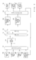
- Fig. 1 is a block diagram showing a general setup of a mixing console in accordance with an embodiment of the present invention.
- the mixing console includes a display 202, which displays various information to the user on the basis of display information supplied via a bus 220.
- the mixing console also includes an electromotive fader unit 204, which, when operated by the user, outputs its operated position via the bus 220 and is driven in accordance with setting information supplied via the bus 220 so that a fader position is automatically set.
- reference numeral 206 represents an operator unit, which includes volume operators for setting tone color parameters, such as filter characteristics, monitoring position, contents to be displayed on the display 202, etc. These operators of the operator unit 206 too can be driven electrically so that their operated positions can be automatically set on the basis of setting information.
- Reference numeral 208 represents a waveform I/O section, which inputs and outputs analog or digital audio signals to and from the mixing console.
- mixing processing, effect processing, etc. of various audio signals are all performed in a digital manner.
- many of audio signals to be input and output from and to outside the mixing console are analog signals. Therefore, a plurality of cards having various functions, such as microphone level analog input, line level analog input, digital input, analog output and digital output functions, are inserted in the waveform I/O section 208 as may be necessary, so that any necessary conversion processes can be carried out by these inserted cards.
- Reference numeral 210 represents a signal processing section, which comprises a group of DSPs (Digital Signal Processors).
- the signal processing section 210 performs mixing processing and effect processing on digital audio signals supplied via the waveform I/O section 208, and then sends the processed results back to the waveform I/O section 208.
- Signal I/O section 212 inputs and outputs a time code and other information from and to any of various external equipment.
- the time code supplied from the external equipment will be referred to as an "external time code”.
- Timer 213 counts the current time, and, on the basis of the counted current time, it generates a time code to be used only within the mixing console; such a time code generated by the timer 213 will be referred to as an "internal time code”.
- the mixing console also includes a CPU 214, which controls various components of the mixing console via the bus 220 on the basis of control programs as will be later described.
- 216 represents a flash memory, which stores the control programs, setting information of the mixing console, etc.
- 218 represents a RAM that is used as a working memory of the CPU 214.
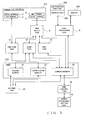
- the signal I/O section 212 includes an SMPTE terminal 2 for receiving an SMPTE time code from video equipment or the like, and an MTC terminal 3 for receiving an MTC (MIDI Time Code) signal that is created by converting the SMPTE time code into the MIDI format.
- the MTC terminal 3 has a same shape as an MIDI signal input/output terminal and a MIDI cable connected to the MTC terminal 3 is one dedicated to the MTC signal.
- reference numeral 4 represents a MIDI terminal for inputting and outputting a MIDI signal from and to MIDI equipment such as a sequencer.
- Reference numeral 5 represents a "ToHOST" terminal, which is mainly connected to a serial port of a personal computer to input and output an MIDI signal from and to the serial port.
- MIDI signals supplied via the MIDI terminal 4 or ToHOST terminal 5 may include MTC signals.
- reference numerals 101-106 and 142-144 represent a plurality of cards inserted in the waveform I/O section 208.
- 102 represents a microphone level analog input card, which, upon receipt of a microphone level analog audio signal, converts the received analog audio signal into a digital audio signal and sends the converted signal to the signal processing signal 210.
- 104 represents a stereo analog input card, which, upon receipt of line level analog audio signals of two channels, converts the received analog audio signals into digital audio signals and sends the converted signals to the signal processing signal 210.
- 106 represents a stereo digital input card, which, upon receipt of stereo digital audio signals, converts the received signals into an internal format of the signal processing signal 210.
- reference numeral 142 represents an analog output card, which converts a digital audio signal, supplied from the signal processing signal 210, into an analog audio signal and outputs the thus-converted converted signal.
- 143 represents a stereo analog output card, which converts digital audio signals of two channels, supplied from the signal processing signal 210, into analog audio signals of two channels (stereo analog audio signals) and outputs the thus-converted converted signals.
- 144 represents a digital output card, which converts a digital audio signal of the internal format, supplied from the signal processing signal 210, into a digital audio signal of a predetermined format, such as AES/EBU, ADAT or TASCAM, and outputs the thus-converted digital signal.
- Reference numeral 114 represents an input channel adjustment section, which performs adjustment of tone volume, tone quality, etc. for up to 96 input channels on the basis of user's operation of the electromotive fader unit 204 and operator unit 206.
- Input patch section 112 assigns digital audio signals, supplied from any of the input cards 102, 104, 106, etc., to given channels of the input channel adjustment section 114.
- reference numeral 118 represents a "10-channel" mixing (MIX) bus unit, which mixes faded (post-fade) digital audio signals on a channel-by-channel basis. For each of the input channels, setting can be made as to whether the audio signal of the channel in question is to be supplied to the MIX bus unit 118.
- MIX output channel section 130 performs level control, channel by channel, on mixed results MIX1 - MIX10 of the individual channels from the 10-channel" mixing bus unit 118 and outputs the thus level-controlled mixed signals.
- the individual input channels can be subjected to 12-channel tone volume adjustment separately from the tone volume control by the electromotive fader unit 204, and the results of such tone volume adjustment are supplied via a 12-channel AUX bus unit 124 to an AUX output section 132.
- Reference numeral 108 represents an internal (built-in) effecter, which performs effect processing on up to eight output channels, and feeds the results of the effect processing back to the input channel adjustment section 114 via the input patch section 112.
- an automix region 20 for the automix function, an automix region 20, library/scene region 22 and current region 24 are secured in the RAM 218.
- automix data are stored.
- automix data generically refer to various event data corresponding to user's operation of the electromotive fader unit 204, operator unit 206, etc.
- Each of the event data includes operation data and a time stamp.
- the library/scene region 22 is capable of storing a plurality of sets of the contents stored in the current region 24. For example, by storing, in the library/scene region 22, given contents stored in the current region 24 at a given time point, it is possible to reproduce (recall) settings at that time point through one touch of a predetermined operator.
- reference numeral 6 represents a MIDI I/O task, which receives MIDI data received via the MIDI terminal 4 or ToHOST terminal 5.
- Various types of MIDI data pertain to behavior of the mixing console.
- the MIDI I/O task 6. the following operations are carried out in accordance with the types of the MIDI data.
- the electromotive fader unit 204 and operator unit 206 of the mixing control can be controlled in accordance with MIDI signals supplied from the external equipment. Specifically, contents of operation performed are supplied as a "control change" included in the MIDI signals. When such data has been supplied, the corresponding data stored in the current region 24 is rewritten directly by the MIDI I/O task 6.
- commands such as a start, stop and locate commands
- MMC MIDI Machine Control
- the data mentioned in items (1) and (2) above are supplied after being bulk-dumped into binary codes, and the automix data are supplied from an external source after being bulk-damped.
- the contents of the data are transferred to a dump task 14.
- the supplied MIDI signals may include an MTC signal.
- MTC signal When such an MTC signal has been supplied, the contents of the signal are transferred to a time code task 12.
- reference numeral 8 represents a panel processing task, which, when the electromotive fader unit 204 or operator unit 206 has been operated by the user, causes the contents of the user operation to be reflected in the current region 24. Once the contents stored in the current region 24 are updated by another task, the electromotive fader unit 204 or operator unit 206 is driven by the panel processing task 8 on the basis of the updated contents. Further, because contents to be displayed on the display 202 are also stored in the current region 24, the contents can be read out by the panel processing task 8 and reflected on the display 202.
- an external time code is received directly from the SMPTE terminal 2 or MTC terminal 3, or an external time code is received indirectly from the MIDI terminal 4 or ToHOST terminal 5 via the MIDI I/O task 6.
- the current time counted by the timer 213 is set or corrected, and an internal time code representing the current time is written into the current region 24.
- dump data supplied via the MIDI I/O task 6 is transferred to the current region 24, library/scene region 22 or automix region 20. Further, data is transferred, by the dump task 14, between the regions 20, 22 and 24.
- Reference numeral 30 represents an automix task, which performs recording and reproducing processing on the automix region 20. Namely, when automix data are to be recorded, the automix task reads out the stored contents of the current region 24 periodically, and writes information to be recorded into the automix region 20. When automix data are to be reproduced, on the other hand, the automix task sequentially reads out event data stored in the automix region 20 and updates the corresponding data in the current region 24.
- 32 represents a DSP control task, which updates arithmetic processing algorithms and parameters of the individual DSPs in the signal processing section 210 on the basis of the data currently written in the current region 24.
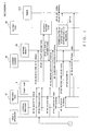
- the user selects a desired type of external time code (external "TC" signal) from among various types, such as "30", “30drop”, "25” and “24", via the operator unit 206 of the mixing console, at step SP100.
- the thus-selected type of external time code is written, at step SP102, to a predetermined location within the automix region 20.
- the mixing console may identify the type of a time code supplied from the external equipment, to thereby automatically select a type of time code.
- the panel processing task 8 performs an operation to activates the automix task 30 at step SP106.
- all automix flags in the current region 24 are cleared to a value "0", at step SP107.
- the "automix flags” are provided, in the current region 24, in corresponding relation to various data to be recorded as the automix data, each of which indicates whether or not the corresponding data has been updated in correspondence with the data stored in the current region 24 and recordable as automix data.
- Each of the automix flags is set to a value "1" when the corresponding data has been updated, but set to a value "0" when the corresponding data has not been updated.
- the located-at position (time point) is recorded into the automix region 20. Further, the located-at position (time point) is also informed to the automix task 30 at step SP112.
- the user's locating operation is also informed as a locate command to the external equipment, and, in the external equipment having received the locate command, a locate process is performed to set the internal time code of the external equipment to the time point designated by the locate command. Conversely, when the mixing console has received a locate command from the external equipment, a similar locate process is performed to set the internal time code of the mixing console to the time point designated by the locate command.
- the informed located-at position is stored, and preparations are made for recording the automix data, at step SP114.
- an internal counter of the timer 213 is reset to a predetermined initial counting value, at step SP116.
- these settings are stored in the automix region 20 at step SP122. Examples of the settings to be made at step SP120 include selection of an absolute value /relative value of operation of the fader/encoder, a channel for which the user's operation is to be recorded, recording elements (elements to be recorded).
- any of the following elements 1 ⁇ - 7 ⁇ may be selected:
- steps SP100, SP104, SP108 and SP120 above need not necessarily be carried out in the order as illustrated in Fig. 4 and the order may be modified as necessary.
- the external equipment such as a video tape recorder, sequencer or the like connected to the signal I/O section 212
- an external time code generated by the external equipment is supplied to the time code task 12 at step S124, so that the supplied external time code is recorded by the time code task 12 into the current region 24 at step SP126.
- the external time code supplied from the external equipment starts incrementing with the current time set by the locate process and can be assumed to be the same type as the one selected at step SP100, they are stored in the current region 24 without being converted, and the time code displayed on the display 202 is updated by the panel processing task 8. Also, the timer 213 is activated with the time value of the supplied external time code as an initial counting value, at step SP128.
- timer 213 Once the timer 213 is activated, its internal counter starts counting a subsequent time at a "600 Hz" frequency. In this way, an internal time code of a "600” resolution is generated.
- the "600” resolution is the least common multiple of per-second resolution "30", “25” and “24” of various external time codes.
- a time interrupt signal is generated and given to the automix task 30 per three clock pulses of an internal clock, i.e. every 5 msec, at step SP134. Other operations will be described later. Different operations are carried out subsequently in accordance with events generated, as explained blow on an event-by-event basis.
- the supply of the external time code is detected by the time code task 12, at step SP150. Then, the external time code is recorded into a predetermined location of the current region 24, at step SP152. Then, at step SP154, the count (currently counted time value) of the timer 213 is corrected to coincide with the supplied external time code, so that an internal time code to be generated from that time on will be corrected accordingly.
- the external time code comprises data indicative of the "hour”, “minute”, "second” and "frame number".
- the "frame number” is set to a value "0" at the beginning of every second and sequentially incremented over a range from “0" to "P-1", if the resolution of the external time code is represented by "P".
- the time code task 12 Upon completion of the above-described operations, the time code task 12 is kept in a standby state until an external time code is supplied again.
- the external time code written in the current region 24 is read out by the panel processing task 8 as necessary and displayed on the display 202 along with the type of the external time code designated earlier at step SP100.
- the time code displayed on the display 202 is nothing but the external time code received by the time code task 12, not the count of the timer 213, and the resolution of the time code varies depending on the type of the external time code.
- the automix task 30 After completion of the automix-data recording preparations at step SP114, the automix task 30 is kept in a standby state until generation of a time interrupt event at step SP136. Once a time interrupt event occurs at step SP134, an internal time code is read out from the timer 213 and converted into a time code of the type selected by the user at step SP100. The thus-converted time code is written into the current region 24 at step SP138, and the time code displayed on the display 202 is converted by the panel processing task 8. Then, the processing proceeds to step SP140, where the automix flags in the current region 24 are checked so that each updated data is extracted from among the data pertaining to the recording elements. For each of the extracted recording elements, the automix flag is cleared to the value "0".
- step SP142 the operation data of each of the updated recording elements and the time stamp corresponding to the current internal time code are recorded as event data into the automix region 20, at step SP144.
- the instant embodiment is characterized in that the internal time code output from the timer 213 is used as the time stamp in the event data. Namely, when the event data of the automix data is to be recorded in the instant embodiment, the internal time code having been converted in the above-described manner is used as the time stamp of the event data, without the external time code being used directly for recording. As a consequence, same automix data can be produced irrespective of the type of the external time code.
- the thus-produced automix data can be synchronized, with a high accuracy, to the external time code of any type. Because, in the instant embodiment, one interrupt event is generated at step SP134 every there clock pulses, a time code having one third of the resolution of the internal time code may be used as the time stamp of the automix data.
- this recording stop operation event is detected by the panel processing task 8 at step SP160, and a recording stop command is supplied to the automix task 30 at step SP162.
- the automix task 30 stops further recording into the automix region 20 at step SP164, and the timer 213 is also deactivated at step SP166.
- the automix task 30 is terminated at step SP172.
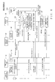
- the user first selects a desired type of external time code via the operator unit 206 of the mixing console, at step SP200.
- the thus-selected type of external time code is written into a predetermined location of the automix region 20, at step SP202.
- the panel processing task 8 performs an operation to activate the automix task 30 at step SP206. Note that if the automix region 20 has a plurality of sets of automix data stored therein, a selection is made at step SP204 as to which of the stored sets of automix data is to be reproduced.
- step SP207 Once the automix task 30 is activated, all the automix flags in the current region 24 are cleared to the value "0", at step SP207. Then, when the user has performed operation to locate the current time at a desired time point at step SP208, the user's operation is informed as a locate command to the external equipment, and the located-at position (time point) is recorded into the automix region 20 by the panel processing task 8. The located-at position (time point) is also informed to the automix task 30, at step SP212. These operations are similar to the above-described operations of steps SP100 to SP112 in the recording processing.
- an operational state at the informed located-at position is reproduced (access is made to the beginning of the operational state at the informed located-at position) at step SP214, and the internal counter of the timer 213 is reset to its initial counting value at step SP216.
- the contents of all operation designated as the "recording elements”
- the recording elements are recorded as event data in the automix data
- automix data may be generated while overwriting is performed a plurality of times.
- one or more channels to be reproduced from among the automix data are designated by the user as may be necessary (SP220), and the designated channels to be reproduced are written into the current region 24 at step SP222 and also informed to the automix task 30.
- steps SP200, SP204, SP208 and SP220 above need not necessarily be carried out in the order illustrated in the figure and the order may be modified as necessary.
- an external time code is supplied to the time code task 12 at step SP224 and the external time code is recorded into the current region 24 by the time code task 12 at step SP226, in the same manner as in the recording processing.
- the timer 213 is activated to start counting with the time point represented by the external time code, at step SP228. In this way, the timer 213 starts counting a subsequent time at a "600 Hz" frequency to output an internal time code, in the same manner as in the recording processing. Operations corresponding to various events will be described below on an event-by-event basis.
- the supply of the external time code is detected by the time code task 12, at step SP250. Then, the external time code is recorded into a predetermined location of the current region 24, at step SP252. Then, at step SP254, the count (currently counted time value) of the timer 213 is corrected to coincide with the supplied external time code.
- step SP214 After completion of the time locating operation at step SP214, the automix task 30 is kept in a standby state until generation of a time interrupt event, at step SP236. Once such a time interrupt event occurs at step SP234, an internal time code corresponding to the current time is read out from the timer 213 and written into the current region 24 at step SP238. Then, the processing proceeds to step SP240, where all the event data having the time stamp corresponding to the internal time code and previous time stamps are read out from the automix region 20.
- step SP242 where are extracted the operation data of the event data to be reproduced from among the read-out event data (if channels to be reproduced have been designated at step SP220, the event data of these channels to be reproduced). Then, the corresponding data in the current region 24 are updated on the basis of the extracted operation data, and such updating is informed to each related task. Thus, the stored contents of the current region 24 are read out by the related tasks as necessary.
- step SP260 Once the user operates a predetermined reproducing stop switch of the operator unit 206, this event is detected by the panel processing task 8 at step SP260, and a recording stop command is supplied to the automix task 30 at step SP262. Thus, the automix task 30 stops further reproduction at step SP264, and the timer 213 is also deactivated at step SP266. Then, once the user performs predetermined operation on the operator unit 206 to disable the automix function at step SP270. the automix task 30 is terminated at step SP272.
- the present invention is characterized in that operation data is recorded/reproduced with a first time code of a higher time resolution than a second time code.
- the present invention can perform recording/reproducing processing on the operation data with enhanced synchronism.
- the resolution of the first time code is a common multiple of a plurality of resolution of the second time code
- the first time code can be readily corrected on the basis of the second time code.
- a second time code of the designated type can be generated on the basis of the same first time code and displayed or output otherwise.
- the present invention relates to the subject matter of Japanese Patent Application No. 2002-206777 filed on July 16, 2002, the disclosure of which is expressly incorporated herein by reference in its entirety.
Landscapes
- Engineering & Computer Science (AREA)
- Multimedia (AREA)
- Signal Processing (AREA)
- Indexing, Searching, Synchronizing, And The Amount Of Synchronization Travel Of Record Carriers (AREA)
- Television Signal Processing For Recording (AREA)
- Electrophonic Musical Instruments (AREA)
- Studio Devices (AREA)
Applications Claiming Priority (2)
| Application Number | Priority Date | Filing Date | Title |
|---|---|---|---|
| JP2002206777A JP3760897B2 (ja) | 2002-07-16 | 2002-07-16 | 操作情報記録再生装置およびタイムコード発生装置 |
| JP2002206777 | 2002-07-16 |
Publications (2)
| Publication Number | Publication Date |
|---|---|
| EP1383260A2 true EP1383260A2 (fr) | 2004-01-21 |
| EP1383260A3 EP1383260A3 (fr) | 2009-01-28 |
Family
ID=29774607
Family Applications (1)
| Application Number | Title | Priority Date | Filing Date |
|---|---|---|---|
| EP03016063A Withdrawn EP1383260A3 (fr) | 2002-07-16 | 2003-07-15 | Dispositif et procédé d'enregistrement/reproduction d'information de fonctionnement en association avec vidéo ou musique |
Country Status (4)
| Country | Link |
|---|---|
| US (1) | US7382966B2 (fr) |
| EP (1) | EP1383260A3 (fr) |
| JP (1) | JP3760897B2 (fr) |
| CN (2) | CN1288908C (fr) |
Families Citing this family (8)
| Publication number | Priority date | Publication date | Assignee | Title |
|---|---|---|---|---|
| NL1014526C2 (nl) | 2000-02-29 | 2001-08-30 | N2It Dev B V I O | Schijf te gebruiken in een inrichting voor signaalbewerking, alsmede een dergelijke inrichting. |
| US8630727B2 (en) * | 2005-08-26 | 2014-01-14 | Endless Analog, Inc | Closed loop analog signal processor (“CLASP”) system |
| US9070408B2 (en) | 2005-08-26 | 2015-06-30 | Endless Analog, Inc | Closed loop analog signal processor (“CLASP”) system |
| US7751916B2 (en) * | 2005-08-26 | 2010-07-06 | Endless Analog, Inc. | Closed loop analog signal processor (“CLASP”) system |
| JP5059677B2 (ja) * | 2008-04-18 | 2012-10-24 | ルネサスエレクトロニクス株式会社 | ノイズ除去装置、及びノイズ除去方法 |
| US10798270B2 (en) | 2017-03-10 | 2020-10-06 | Sling Media Pvt. Ltd. | Synchronizing media in multiple devices |
| EP3716262B1 (fr) * | 2018-10-19 | 2025-09-17 | Sony Group Corporation | Dispositif, procédé et programme de traitement d'informations |
| CN113742042B (zh) * | 2021-08-26 | 2023-08-25 | 苏州浪潮智能科技有限公司 | 一种定时器处理方法、装置、设备及可读存储介质 |
Citations (4)
| Publication number | Priority date | Publication date | Assignee | Title |
|---|---|---|---|---|
| US5146448A (en) * | 1988-02-04 | 1992-09-08 | Matsushita Electric Industrial Co., Ltd. | Time code recording or reproducing apparatus and time code converter |
| JPH0721682A (ja) * | 1993-06-29 | 1995-01-24 | Sony Corp | ミキシングコンソール装置の制御装置 |
| EP0831488A2 (fr) | 1996-09-23 | 1998-03-25 | Sony Electronics Inc. | Méthodes et appareil pour traiter des codes temporels |
| US20010041049A1 (en) | 1996-12-25 | 2001-11-15 | Takeshi Kanda | Editing system and editing method |
Family Cites Families (3)
| Publication number | Priority date | Publication date | Assignee | Title |
|---|---|---|---|---|
| JP2733524B2 (ja) * | 1986-11-13 | 1998-03-30 | ソニー株式会社 | 記録装置 |
| JP2797810B2 (ja) * | 1992-02-04 | 1998-09-17 | ヤマハ株式会社 | ディジタルオーディオ機器 |
| JPH1066036A (ja) * | 1996-08-15 | 1998-03-06 | Oki Electric Ind Co Ltd | Tv方式変換装置 |
-
2002
- 2002-07-16 JP JP2002206777A patent/JP3760897B2/ja not_active Expired - Fee Related
-
2003
- 2003-07-15 EP EP03016063A patent/EP1383260A3/fr not_active Withdrawn
- 2003-07-16 US US10/621,024 patent/US7382966B2/en not_active Expired - Fee Related
- 2003-07-16 CN CNB031476872A patent/CN1288908C/zh not_active Expired - Fee Related
- 2003-07-16 CN CNU03275843XU patent/CN2691202Y/zh not_active Expired - Lifetime
Patent Citations (4)
| Publication number | Priority date | Publication date | Assignee | Title |
|---|---|---|---|---|
| US5146448A (en) * | 1988-02-04 | 1992-09-08 | Matsushita Electric Industrial Co., Ltd. | Time code recording or reproducing apparatus and time code converter |
| JPH0721682A (ja) * | 1993-06-29 | 1995-01-24 | Sony Corp | ミキシングコンソール装置の制御装置 |
| EP0831488A2 (fr) | 1996-09-23 | 1998-03-25 | Sony Electronics Inc. | Méthodes et appareil pour traiter des codes temporels |
| US20010041049A1 (en) | 1996-12-25 | 2001-11-15 | Takeshi Kanda | Editing system and editing method |
Non-Patent Citations (1)
| Title |
|---|
| "Handbook of Time Code Formats", 1 December 1987 (1987-12-01), XP055159851, Retrieved from the Internet <URL:http://www.vk7krj.com/ham_stuff_pics/Handbook_of_Time_Code_Formats.pdf> [retrieved on 20141222] * |
Also Published As
| Publication number | Publication date |
|---|---|
| EP1383260A3 (fr) | 2009-01-28 |
| CN1479556A (zh) | 2004-03-03 |
| US7382966B2 (en) | 2008-06-03 |
| CN1288908C (zh) | 2006-12-06 |
| JP3760897B2 (ja) | 2006-03-29 |
| JP2004056176A (ja) | 2004-02-19 |
| CN2691202Y (zh) | 2005-04-06 |
| US20040017998A1 (en) | 2004-01-29 |
Similar Documents
| Publication | Publication Date | Title |
|---|---|---|
| US7139625B2 (en) | Audio signal processing device | |
| CN102740216B (zh) | 混音设备 | |
| US7694230B2 (en) | Digital mixer and program | |
| US5026051A (en) | Sound imaging apparatus for a video game system | |
| US20070043462A1 (en) | Configuration method of digital audio mixer | |
| EP1383260A2 (fr) | Dispositif et procédé d'enregistrement/reproduction d'information de fonctionnement en association avec vidéo ou musique | |
| US8312375B2 (en) | Digital mixer | |
| JP4597276B2 (ja) | 表示装置 | |
| US20040159218A1 (en) | Mixing system control method, apparatus and program | |
| US8064621B2 (en) | Digital mixer | |
| JP2013110585A (ja) | 音響機器 | |
| JP2004247898A (ja) | ミキシングシステムの制御方法、ミキシングシステムおよびプログラム | |
| EP2166453B1 (fr) | Appareil électronique et programme de contrôle d'ordinateur | |
| US7450728B2 (en) | Parameter control method and program therefor, and parameter setting apparatus | |
| US20110026738A1 (en) | Mixing Apparatus | |
| JP5125527B2 (ja) | 多重録音装置 | |
| US6560400B1 (en) | Video information editing method and system, and recording medium having the editing method stored | |
| JP6026230B2 (ja) | 音声調整卓 | |
| EP2701151A2 (fr) | Enregistreur multipiste | |
| US20050185805A1 (en) | Parameter setting apparatus for audio mixer, and program therefor | |
| JP4413283B2 (ja) | Aux・send名称表示システム | |
| KR0146453B1 (ko) | 비디오테이프의 예약녹화 제어장치와 그 방법 | |
| JP2007074623A (ja) | デジタルミキサおよびプログラム | |
| US20070103591A1 (en) | Method for managing key operation information for a jog key | |
| JP5560760B2 (ja) | 音響信号処理装置およびプログラム |
Legal Events
| Date | Code | Title | Description |
|---|---|---|---|
| PUAI | Public reference made under article 153(3) epc to a published international application that has entered the european phase |
Free format text: ORIGINAL CODE: 0009012 |
|
| 17P | Request for examination filed |
Effective date: 20030715 |
|
| AK | Designated contracting states |
Kind code of ref document: A2 Designated state(s): AT BE BG CH CY CZ DE DK EE ES FI FR GB GR HU IE IT LI LU MC NL PT RO SE SI SK TR |
|
| AX | Request for extension of the european patent |
Extension state: AL LT LV MK |
|
| RAP1 | Party data changed (applicant data changed or rights of an application transferred) |
Owner name: YAMAHA CORPORATION |
|
| PUAL | Search report despatched |
Free format text: ORIGINAL CODE: 0009013 |
|
| AK | Designated contracting states |
Kind code of ref document: A3 Designated state(s): AT BE BG CH CY CZ DE DK EE ES FI FR GB GR HU IE IT LI LU MC NL PT RO SE SI SK TR |
|
| AX | Request for extension of the european patent |
Extension state: AL LT LV MK |
|
| 17Q | First examination report despatched |
Effective date: 20090319 |
|
| AKX | Designation fees paid |
Designated state(s): DE FR GB IT |
|
| RIC1 | Information provided on ipc code assigned before grant |
Ipc: H04H 60/04 20080101AFI20120905BHEP |
|
| STAA | Information on the status of an ep patent application or granted ep patent |
Free format text: STATUS: THE APPLICATION IS DEEMED TO BE WITHDRAWN |
|
| 18D | Application deemed to be withdrawn |
Effective date: 20170321 |