EP1384893B1 - Moteur électrique et compresseur hermétique - Google Patents
Moteur électrique et compresseur hermétique Download PDFInfo
- Publication number
- EP1384893B1 EP1384893B1 EP03016419.8A EP03016419A EP1384893B1 EP 1384893 B1 EP1384893 B1 EP 1384893B1 EP 03016419 A EP03016419 A EP 03016419A EP 1384893 B1 EP1384893 B1 EP 1384893B1
- Authority
- EP
- European Patent Office
- Prior art keywords
- stator core
- electric motor
- housing
- circumferential surface
- circumferential wall
- Prior art date
- Legal status (The legal status is an assumption and is not a legal conclusion. Google has not performed a legal analysis and makes no representation as to the accuracy of the status listed.)
- Expired - Lifetime
Links
- 239000011800 void material Substances 0.000 claims description 66
- 230000006835 compression Effects 0.000 claims description 18
- 238000007906 compression Methods 0.000 claims description 18
- 230000007246 mechanism Effects 0.000 claims description 18
- XAGFODPZIPBFFR-UHFFFAOYSA-N aluminium Chemical compound [Al] XAGFODPZIPBFFR-UHFFFAOYSA-N 0.000 claims description 12
- 229910052782 aluminium Inorganic materials 0.000 claims description 12
- 229910000831 Steel Inorganic materials 0.000 claims description 5
- 229920001296 polysiloxane Polymers 0.000 claims description 5
- 239000010959 steel Substances 0.000 claims description 5
- 229910000838 Al alloy Inorganic materials 0.000 claims description 2
- 238000004804 winding Methods 0.000 claims 1
- 239000003507 refrigerant Substances 0.000 description 18
- 230000000694 effects Effects 0.000 description 14
- 238000004378 air conditioning Methods 0.000 description 8
- 230000005489 elastic deformation Effects 0.000 description 7
- 239000011295 pitch Substances 0.000 description 7
- XEEYBQQBJWHFJM-UHFFFAOYSA-N Iron Chemical compound [Fe] XEEYBQQBJWHFJM-UHFFFAOYSA-N 0.000 description 6
- 230000006866 deterioration Effects 0.000 description 3
- 238000004512 die casting Methods 0.000 description 3
- 229910052742 iron Inorganic materials 0.000 description 3
- 230000008859 change Effects 0.000 description 2
- 239000002826 coolant Substances 0.000 description 2
- 238000004519 manufacturing process Methods 0.000 description 2
- 239000000463 material Substances 0.000 description 2
- 230000009471 action Effects 0.000 description 1
- 238000001816 cooling Methods 0.000 description 1
- 238000013016 damping Methods 0.000 description 1
- 230000001419 dependent effect Effects 0.000 description 1
- 238000011161 development Methods 0.000 description 1
- 230000018109 developmental process Effects 0.000 description 1
- 230000004907 flux Effects 0.000 description 1
- 239000000446 fuel Substances 0.000 description 1
- 238000002955 isolation Methods 0.000 description 1
- 239000007769 metal material Substances 0.000 description 1
- 239000012811 non-conductive material Substances 0.000 description 1
- 230000002265 prevention Effects 0.000 description 1
- 230000009467 reduction Effects 0.000 description 1
- 239000011347 resin Substances 0.000 description 1
- 229920005989 resin Polymers 0.000 description 1
Images


Classifications
-
- F—MECHANICAL ENGINEERING; LIGHTING; HEATING; WEAPONS; BLASTING
- F04—POSITIVE - DISPLACEMENT MACHINES FOR LIQUIDS; PUMPS FOR LIQUIDS OR ELASTIC FLUIDS
- F04C—ROTARY-PISTON, OR OSCILLATING-PISTON, POSITIVE-DISPLACEMENT MACHINES FOR LIQUIDS; ROTARY-PISTON, OR OSCILLATING-PISTON, POSITIVE-DISPLACEMENT PUMPS
- F04C28/00—Control of, monitoring of, or safety arrangements for, pumps or pumping installations specially adapted for elastic fluids
- F04C28/28—Safety arrangements; Monitoring
-
- F—MECHANICAL ENGINEERING; LIGHTING; HEATING; WEAPONS; BLASTING
- F04—POSITIVE - DISPLACEMENT MACHINES FOR LIQUIDS; PUMPS FOR LIQUIDS OR ELASTIC FLUIDS
- F04C—ROTARY-PISTON, OR OSCILLATING-PISTON, POSITIVE-DISPLACEMENT MACHINES FOR LIQUIDS; ROTARY-PISTON, OR OSCILLATING-PISTON, POSITIVE-DISPLACEMENT PUMPS
- F04C23/00—Combinations of two or more pumps, each being of rotary-piston or oscillating-piston type, specially adapted for elastic fluids; Pumping installations specially adapted for elastic fluids; Multi-stage pumps specially adapted for elastic fluids
- F04C23/008—Hermetic pumps
-
- F—MECHANICAL ENGINEERING; LIGHTING; HEATING; WEAPONS; BLASTING
- F04—POSITIVE - DISPLACEMENT MACHINES FOR LIQUIDS; PUMPS FOR LIQUIDS OR ELASTIC FLUIDS
- F04C—ROTARY-PISTON, OR OSCILLATING-PISTON, POSITIVE-DISPLACEMENT MACHINES FOR LIQUIDS; ROTARY-PISTON, OR OSCILLATING-PISTON, POSITIVE-DISPLACEMENT PUMPS
- F04C29/00—Component parts, details or accessories of pumps or pumping installations, not provided for in groups F04C18/00 - F04C28/00
- F04C29/04—Heating; Cooling; Heat insulation
- F04C29/045—Heating; Cooling; Heat insulation of the electric motor in hermetic pumps
-
- H—ELECTRICITY
- H02—GENERATION; CONVERSION OR DISTRIBUTION OF ELECTRIC POWER
- H02K—DYNAMO-ELECTRIC MACHINES
- H02K1/00—Details of the magnetic circuit
- H02K1/06—Details of the magnetic circuit characterised by the shape, form or construction
- H02K1/12—Stationary parts of the magnetic circuit
- H02K1/14—Stator cores with salient poles
- H02K1/146—Stator cores with salient poles consisting of a generally annular yoke with salient poles
-
- H—ELECTRICITY
- H02—GENERATION; CONVERSION OR DISTRIBUTION OF ELECTRIC POWER
- H02K—DYNAMO-ELECTRIC MACHINES
- H02K1/00—Details of the magnetic circuit
- H02K1/06—Details of the magnetic circuit characterised by the shape, form or construction
- H02K1/12—Stationary parts of the magnetic circuit
- H02K1/18—Means for mounting or fastening magnetic stationary parts on to, or to, the stator structures
- H02K1/185—Means for mounting or fastening magnetic stationary parts on to, or to, the stator structures to outer stators
-
- H—ELECTRICITY
- H02—GENERATION; CONVERSION OR DISTRIBUTION OF ELECTRIC POWER
- H02K—DYNAMO-ELECTRIC MACHINES
- H02K5/00—Casings; Enclosures; Supports
- H02K5/04—Casings or enclosures characterised by the shape, form or construction thereof
-
- H—ELECTRICITY
- H02—GENERATION; CONVERSION OR DISTRIBUTION OF ELECTRIC POWER
- H02K—DYNAMO-ELECTRIC MACHINES
- H02K7/00—Arrangements for handling mechanical energy structurally associated with dynamo-electric machines, e.g. structural association with mechanical driving motors or auxiliary dynamo-electric machines
- H02K7/14—Structural association with mechanical loads, e.g. with hand-held machine tools or fans
-
- F—MECHANICAL ENGINEERING; LIGHTING; HEATING; WEAPONS; BLASTING
- F04—POSITIVE - DISPLACEMENT MACHINES FOR LIQUIDS; PUMPS FOR LIQUIDS OR ELASTIC FLUIDS
- F04C—ROTARY-PISTON, OR OSCILLATING-PISTON, POSITIVE-DISPLACEMENT MACHINES FOR LIQUIDS; ROTARY-PISTON, OR OSCILLATING-PISTON, POSITIVE-DISPLACEMENT PUMPS
- F04C18/00—Rotary-piston pumps specially adapted for elastic fluids
- F04C18/02—Rotary-piston pumps specially adapted for elastic fluids of arcuate-engagement type, i.e. with circular translatory movement of co-operating members, each member having the same number of teeth or tooth-equivalents
- F04C18/0207—Rotary-piston pumps specially adapted for elastic fluids of arcuate-engagement type, i.e. with circular translatory movement of co-operating members, each member having the same number of teeth or tooth-equivalents both members having co-operating elements in spiral form
- F04C18/0215—Rotary-piston pumps specially adapted for elastic fluids of arcuate-engagement type, i.e. with circular translatory movement of co-operating members, each member having the same number of teeth or tooth-equivalents both members having co-operating elements in spiral form where only one member is moving
Definitions
- the present invention relates to an electric motor and to an electric type compressor, which is formed by integrating the electric motor with a compression mechanism.
- Japanese Unexamined Patent Publication No. 2003-56463 discloses this type of electric type compressor, which is integrally provided with the electric motor, is used in a vehicle air conditioning apparatus.
- a circular stator core for the electric motor is tightly fitted inside of a cylindrical housing by shrink fit and press fit. Since fixing the stator core by the tight fit is relatively simple and easy, cost of the electric type compressor is lowered.
- US 5 218 252 A discloses an electric motor having the features of the preamble of claim 1.
- the electric motor has a housing containing a stator, wherein four circumferential space sections are provided between the inner circumferential surface of the housing and the outer circumferential surface of the stator.
- DE 740 531 C discloses a housing containing a stator wherein four circumferential space sections are provided between the inner circumferential surface of the housing and the outer circumferential surface of the stator, and wherein in each circumferential space section there is an inclined projection for holding the stator.
- EP 1 209 796 A2 discloses a housing containing a stator, wherein a plurality of circumferential space sections are provided between the inner circumferential surface of the housing and the outer circumferential surface of the stator.
- DE 199 60 088 A1 discloses a housing containing a stator. In the outer circumferential surface of the stator there are many recesses. Further, between the housing and the stator there is provided a vibration damping layer.
- DE 20 42 239 A1 discloses a housing containing a stator. At the edge of the stator there are an isolation layer and coils beneath the housing.
- DE 199 59 422 A1 discloses a housing containing a stator. Cooling medium channels are provided between the outer circumferential surface of the stator and the inner circumferential surface of the housing. The cooling medium channels are grooved into the outer circumferential surface of the stator and extend in parallel to the shaft.
- EP 1 143 599 A2 discloses a housing containing a stator. Between the housing and the stator there is provided a layer of a non-conductive material.
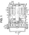
- FIG. 1 a left side of the FIG. 1 is a front side of the compressor and a right side thereof is a rear side of the compressor. It is noted that Figures 1 to 6 show examples for illustration. The invention is shown in Figures 7 and 8 .
- a first housing component 11a is fixedly joined to a second housing component 11b to form the configuration of the compressor or a compressor housing 11. Thereby, an enclosed space 30 is defined in the compressor housing 11.
- the first housing component 11a has a cylindrical circumferential wall 25 and a bottom at the rear side.
- the first housing component 11a is manufactured by die casting of aluminum.
- the aluminum includes aluminum alloy.
- the second housing component 11b is in a cylindrical shape and has a cover at the front side.
- the second housing component 11b is also manufactured by die casting of the aluminum.
- the electric type compressor provided with the compressor housing 11 is suitable especially for installing on vehicles in order to improve fuel efficiency.
- the first and second housing components 11a and 11b are each manufactured by die casting, in comparison with a case that the first and second housing components 11a and 11b are each manufactured by press work, the shape of the compressor housing 11 has a large degree of freedom. Therefore, a pin for installing the electric type compressor on the vehicle, which is not shown in the drawings, is easily integrally formed with the compressor housing 11, that is, the first housing component 11a and/or the second housing component 11b. In this case, the number of parts of the electric type compressor is reduced.
- a rotary shaft 13 is supported for rotation by a front bearing 22 and a rear bearing 23 in the first housing component 11a.
- a rotational central axis L of the rotary shaft 13 is a central axis of the electric type compressor.
- the circumferential wall 25 of the first housing component 11a has a cylindrical inner surface or an inner circumferential surface 25a whose center is located on the central axis L of the electric type compressor.
- the electric motor M is a DC brushless motor and includes a stator 12 and a rotor 14.
- the stator 12 is fixed on the inner circumferential surface 25a of the circumferential wall 25 in the first housing component 11a.
- the rotor 14 is installed on the rotary shaft 13 so as to be surrounded by the stator 12. When electric power is supplied to a coil 15 of the stator 12, the electric motor M rotates the rotary shaft 13.
- a front space 30a and a rear space 30b are defined at the opposite sides in the direction of the axis L of the stator 12. That is, the front space 30a is defined between the stator 12 and the compression mechanism C, which is located at the front side of the stator 12. Also, the rear space 30b is defined at the rear side of the stator 12.
- An inlet 18 is formed through the first housing component 11a so as to correspond to the rear space 30b. The inlet 18 is connected to a piping in an external refrigerant circuit, that is, an external piping 24. The inlet 18 serves as a mouth of the electric type compressor.
- the compression mechanism C is a scroll type and includes a fixed scroll 20 and a movable scroll 21.
- the movable scroll 21 is connected to the rotary shaft 13.
- the movable scroll 21 orbits relative to the fixed scroll 20 in accordance with the rotation of the rotary shaft 13 to compress a refrigerant gas. Therefore, when the compression mechanism C is activated by driving the electric motor M, the refrigerant gas, whose temperature and pressure are relatively low, is drawn from the external refrigerant circuit to the compression mechanism C though the inlet 18, the rear space 30b, the electric motor M and the front space 30a.
- the temperature and pressure of the refrigerant gas, which has been drawn into the compression mechanism C become relatively high by the compressive action of the compression mechanism C.
- the refrigerant gas, whose temperature and pressure are relatively high is discharged from an outlet 19, which is formed through the second housing component 11b, to the external refrigerant circuit.
- the refrigerant gas is circulated through the electric motor M between the external refrigerant circuit and the compression mechanism C. Therefore, the electric motor M is cooled by utilizing the refrigerant gas. Especially, since the refrigerant gas, whose pressure is relatively low in a refrigerating cycle, is circulated through the electric motor M, the electric motor M is effectively cooled.
- the stator 12 of the electric motor M includes the coil 15 and a stator core 16 around which the coil 15 is wound.
- the stator core 16 is formed by layering a plurality of silicone steel plates, which is formed by press work, in the direction of the axis L.
- thermal expansion coefficient of the stator core 16 is different from that of the compressor housing 11, which also serves as a housing of the electric motor M.
- thermal expansion coefficient of the aluminum is larger than that of the silicone steel.
- the stator core 16 includes a circular back yoke 16a whose center is located on the axis L.
- the stator core 16 also includes a plurality of teeth 16b that extends from the inner circumferential surface of the back yoke 16a inward. In the present embodiment, the number of the teeth 16b is six. In the stator core 16, the coil 15 is intensively wound around the teeth 16b.
- the stator 12 is fixed to the first housing component 11a by tightly fitting the stator core 16 to the inner circumferential surface 25a of the circumferential wall 25 of the first housing component 11a.
- the stator 12 is positioned to the first housing component 11a by contacting the rear end surface of the stator core 16 with a step 25b formed at the rear side of the inner circumferential surface 25a of the circumferential wall 25.
- the stator 12 is tightly fitted to the circumferential wall 25 by shrink fit and press fit. Therefore, for example, if the inner circumferential surface 25a of the circumferential wall 25 and an outer circumferential surface 16c of the stator core 16 contact each other in a circular region or in circumference, since the thermal expansion coefficient of the circumferential wall 25 is different from that of the stator core 16, degree of tightness where the stator core 16 is tightened by the circumferential wall 25 is varied in accordance with temperature change of the electric type compressor.
- the interference between the circumferential wall 25 and the stator core 16 is predetermined in such a manner that the circumferential wall 25 and the stator core 16 are not loosened to each other even when the temperature of the electric type compressor becomes relatively high. Therefore, on the contrary, when the temperature of the electric type compressor becomes relatively low, the degree of tightness is excessively increased. Thereby, the circumferential wall 25 and/or the stator core 16 may generate a crack.
- the electric type compressor is structured as follows in such a manner that the circumferential wall 25 does not excessively tightly fit around the stator core 16 even when the temperature of the electric type compressor becomes relatively low.
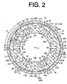
- a void 32 is defined between the inner circumferential surface 25a of the circumferential wall 25 and the outer circumferential surface 16c of the stator core 16, which are pressed to each other by the tight fit, so as to prevent the both circumferential surfaces 25a and 16c from contacting each other in the circular region, whose center is located on the axis L. Also, the void 32 extends along the direction of the axis L and interconnects the front space 30a with the rear space 30b in the enclosed space 30. The void 32 serves as a part of a suction gas passage.
- the number of the voids 32 is plural and a plurality of the voids 32 is formed around the axis L of the stator core 16.
- the number of the voids 32 is six.
- Each void 32 is provided by forming a recess 17 in the outer circumferential surface 16c of the stator core 16.
- each void 32 is a space formed between the associated recess 17 and the circumferential wall 25.
- a plurality of protrusions 31, which is in the shape of prism, remains in the outer circumferential surface 16c of the stator core 16 by forming a plurality of recesses in the outer circumferential surface 16c.
- the distal end surface 31a of the protrusion 31 of the stator core 16 and the inner circumferential surface 25a of the circumferential wall 25 are contacted with each other in a contact region.
- a contacting portion 33 includes the distal end surface 31a and the contact region of the inner circumferential surface 25a.
- the plurality of protrusions 31 is arranged at intervals of an equal angle around the axis L. Therefore, the number of the contacting portions 33 is plural and a plurality of the contacting portions 33 is arranged at intervals of an equal angle around the axis L of the stator core 16. In the present embodiment, the number of the contacting portions 33 is six. Therefore, pitch P between the contacting portions 33, which are located next to each other, are the same in every part around the axis L. That is, the plurality of voids 32 is formed in such a manner that the contacting portions 33 between the circumferential wall 25 and the stator core 16 are arranged at intervals of an equal angle around the axis L of the stator core 16.
- Each recess 17 has a bottom surface in an arched shape.
- a region 17a is located at the opposite sides of the bottom surface in a circumferential direction of the stator core 16.
- the region 17a adjoins the protrusion 31 of the stator core 16 and exists in a first imaginary cylindrical surface S1, whose center is located on the axis L of the stator core 16.
- a thinned portion 17b is formed in the shape of a concave surface so as to cave the first imaginary cylindrical surface S1.
- the thinned portion 17b is located near the proximal end of the teeth 16b where a magnetic flux density is relatively lowered in the stator core 16.
- the object of the thinned portion 17b is mainly to reduce the weight of the stator core 16. Since the thinned portion 17b is formed in the bottom surface of the recess 17, a cross sectional area of the void 32 in a perpendicular plane to the axis L, through which suction refrigerant gas passes, is increased. Therefore, efficiency of intake of the compression mechanism C and cooling efficiency of the electric motor M are improved.
- the inner circumferential surface 25a of the circumferential wall 25 is contacted with the outer circumferential surface 16c of the stator core 16 in the contact region. That is, the inner circumferential surface 25a of the circumferential wall 25 is contacted with the distal end surface 31a of the protrusion 31 in the contacting portion 33.
- the contact region exists in a second imaginary cylindrical surface S2, whose center is also located on the axis L.
- the second imaginary cylindrical surface S2 has the same length as the stator core 16 in the direction of the axis L
- the radial differential between the second imaginary cylindrical surface S2 and the first imaginary cylindrical surface S1, that is, the height of the protrusion 31 that protrudes from the first imaginary cylindrical surface S1 is predetermined in such a manner that a ratio of the radial differential to the radius of the second imaginary cylindrical surface S2 is approximately 5/1000 to 15/1000.
- the electric type compressor according to the present embodiment is set in such a manner that the radius of the second imaginary cylindrical surface S2 is approximately 50 mm. Therefore, the height of the protrusion 31 is approximately 0.25 mm to 0.75 mm. Note that the height of the protrusion 31 is exaggeratedly shown in FIGs. 1 and 2 .
- the inner circumferential surface 25a of the circumferential wall 25 and the outer circumferential surface 16c of the stator core 16 contact each other in the contact region, which has a first predetermined area. Also, the inner circumferential surface 25a of the circumferential wall 25 and the outer circumferential surface 16c of the stator core 16 do not contact each other in a non-contact region, which has a second predetermined area.
- the void 32 is formed in such a manner that the first predetermined area becomes smaller than the second predetermined area. In the present embodiment, specifically, in the second imaginary cylindrical surface S2, a ratio of the first predetermined area to the total area of the first predetermined area and the second predetermined area is 30% or less than 30%.
- the axis L of the stator core 16 and the axis L of the circumferential wall 25 are easily conformed to each other.
- the rotary shaft 13 is installed on the compressor housing 11 through the front bearing 22 and the rear bearing 23, the rotor 14, which is installed on the rotary shaft 13, is hardly interfered with the stator core 16.
- the electric type compressor is easily manufactured.
- the ratio of the height of the protrusion 31 to the radius of the second imaginary cylindrical surface S2 is preferably approximately in a range of 5/1000 to 15/1000.
- the thinned portion 17b is formed so as to correspond to the teeth 16b of the stator core 16.
- the thinned portion 17b is formed so as not to generate the magnetic saturation.
- the thinned portion 17b does not increase the diameter of the stator core 16. Namely, the size of the electric type compressor is not increased.
- the stator core 16 is structured in such a manner that the coil 15 is intensively wounded around the teeth 16b, even if the thinned portion 17b is formed so as to correspond to the teeth 16b of the stator core 16, the magnetic saturation does not generate.
- the stator core 16 is structured in such a manner that the coil 15 is distributively wounded around the teeth 16b, the magnetic saturation may generate by forming the thinned portion 17b in the stator core 16. Therefore, in order to prevent the generation of the magnetic saturation, the diameter of the stator core 16 requires increasing by a radial length of the thinned portion 17b.
- the void 32 is provided by forming the recess 17 in the outer circumferential surface 16c of the stator core 16. Thereby, the void 32 also serves as a part of the suction refrigerant gas passage without increasing the size of the electric type compressor.
- the teeth 16b of the stator core 16 of the electric motor M are relatively compact and the number of the teeth 16b is increased. Specifically, in the present embodiment, the number of the teeth 16b is twenty-four.
- the stator core 16 is structured in such a manner that the coil 15 is distributively wounded around the teeth 16b of the stator core 16. Such structured electric motor M that the coil 15 is distributively wounded around the teeth 16b is more noiseless than the electric motor M, where the coil 15 is intensively wounded around the teeth 16b.
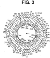
- the void 32 is provided not by forming a recess 36 in the outer circumferential surface 16c of the stator core 16 but by forming the recess 36 in the inner circumferential surface 25a of the circumferential wall 25.
- the number of the recesses 36 is plural and the recesses 36 are formed around the axis L at intervals of an equal angle. In the present embodiment, the number of the recesses 36 is six.
- Each recess 36 extends along the direction of the axis L in the enclosed space 30 of the compressor housing 11 and is formed so as to become larger than the total length in the direction of the axis L of the stator core 16. Thereby, the recess 36 interconnects the front space 30a with the rear space 30b.
- a plurality of protrusions 37 remains in the inner circumferential surface 25a of the circumferential wall 25 by forming a plurality of the recesses 36 in the inner circumferential surface 25a.
- a distal end surface 37a of each protrusion 37 which is in the shape of an arched concave surface, is contacted with a cylindrical outer surface of the stator core 16 or the outer circumferential surface 16c in a contact region.
- the contacting portion 33 includes the distal end surface 37a and the contact region of the outer circumferential surface 16c.
- a bottom surface 36a of each recess 36 is as a whole in the shape of a curved concave surface.
- the inner circumferential surface 25a of the circumferential wall 25 is waved-shaped in the circumferential direction of the stator core 16, and the elastic part 25d of the circumferential wall 25 is thinner than a part of the circumferential wall 25, which corresponds to the contacting portion 33.
- FIG. 4 An electric type compressor for a vehicle air conditioning apparatus according to a third preferred embodiment will now be described with reference to FIG. 4 .
- the third embodiment only different aspects from the second embodiment are described. Identical reference numerals to the second embodiment are applied to the same or corresponding members in the third embodiment and overlapped description is omitted.
- the number of the voids 32, which are provided around the axis L, is three.
- the circumferential wall 25 of the compressor housing 11 and the stator core 16 are contacted with each other at three spots around the axis L of the stator core 16. Therefore, the number of the contacting portions 33 where the stator core 16 is supported by the circumferential wall 25 around the axis L of the stator core 16 is three.
- the recess 36 which is formed in the inner circumferential surface 25a of the circumferential wall 25, is formed by expanding the elastic part 25d outwardly in the radial direction of the circumferential wall 25. Therefore, an outer circumferential surface 25c of the circumferential wall 25 is waved-shaped in the circumferential direction of the stator core 16 similarly to the inner circumferential surface 25a, and is different from an outer circumferential surface of the circumferential wall 25 of the above-described second embodiment, which forms a circumferential surface.
- the circumferential wall 25 is waved-shaped in the circumferential direction of the stator core 16 so as to maintain a substantially uniform thickness, and is formed in such a manner that the thickness of the part of the circumferential wall 25, which corresponds to the contacting portion 33, becomes equal to the thickness of the elastic part 25d.
- FIG. 5 An electric type compressor for a vehicle air conditioning apparatus according to a fourth preferred embodiment will now be described with reference to FIG. 5 .
- the fourth embodiment only different aspects from the third embodiment are described. Identical reference numerals to the third embodiment are applied to the same or corresponding members in the fourth embodiment and overlapped description is omitted.
- the number of the voids 32, which are provided around the axis L is four.
- the circumferential wall 25 of the compressor housing 11 and the stator core 16 are contacted with each other at four spots around the axis L of the stator core 16. Therefore, the number of the contacting portions 33 where the stator core 16 is supported by the circumferential wall 25 around the axis L of the stator core 16 is four.
- FIG. 6 An electric type compressor for a vehicle air conditioning apparatus according to a fifth preferred embodiment will now be described with reference to FIG. 6 .
- the fifth embodiment only different aspects from the third embodiment are described. Identical reference numerals to the third embodiment are applied to the same or corresponding members in the fifth embodiment and overlapped description is omitted.
- the number of the voids 32, which are provided around the axis L, is five.
- the circumferential wall 25 of the compressor housing 11 and the stator core 16 are contacted with each other at five spots around the axis L of the stator core 16. Therefore, the number of the contacting portions 33 where the stator core 16 is supported by the circumferential wall 25 around the axis L of the stator core 16 is five.
- the rigidity of the circumferential wall 25 is lowered.
- the number of spots where the elastic parts 25d or the voids 32 is provided around the axis L of the stator core 16 is six or more than six, and if six or more than six in the plurality of elastic parts 25d are respectively expanded outwardly in the radial direction of the stator core 16, the rigidity of the circumferential wall 25 is excessively enhanced.
- each elastic part 25d is hardly elastically deformed. Therefore, if the circumferential wall 25 and the stator core 16 shrink so as to tightly fit each other due to thermal effect, the circumferential wall 25 excessively tightly fit the stator core 16 because of such a great number of spots.
- FIG. 7 An electric type compressor for a vehicle air conditioning apparatus according to a sixth preferred embodiment of the present invention will now be described with reference to FIG. 7 .
- Identical reference numerals to the fourth embodiment are applied to the same or corresponding members in the sixth embodiment and overlapped description is omitted. Note that in the fourth embodiment the number of voids 32 is four.
- a first void element 32a is provided between the circumferential wall 25 and the stator core 16 by forming the recess 36 in the inner circumferential surface 25a of the circumferential wall 25.
- the recess 36 is formed by outwardly expanding a part of the elastic part 25d of the circumferential wall 25, which corresponds to the recess 36, in the radial direction of the stator core 16.
- a second void element 32b is also provided between the circumferential wall 25 and the stator core 16 by forming the recess 17 in the outer circumferential surface 16c of the stator core 16. Note that in the present embodiment the thinned portion 17b of the first embodiment, which is shown in FIG. 2 , is eliminated from the recess 17.
- the recess 17 of the stator core 16 is set to be longer in the circumferential direction of the stator core 16 than the recess 36 of the circumferential wall 25.
- the recess 36 is arranged in such a manner that an opening of the recess 36 faces a part of the recess 17. Therefore, the first void element 32a, which is provided by the recess 36, is connected to the second void element 32b so as to expand a part of the second void element 32b, which is provided by the recess 17, outwardly in the radial direction of the stator core 16. That is, the void 32 includes the first void element 32a and the second void element 32b.
- each void 32 adjoins two of the voids 32.
- Each void 32 is provided in such a manner that the void 32 and one of the voids 32, which is adjoined to the void 32, are approached to each other between the respective first void elements 32a. Therefore, each void 32 is provided in such a manner that the void 32 and the other void 32, which is adjoined to the void 32, are kept from each other by a relatively large distance in the circumferential direction of the stator core 16 between the first void elements 32a.
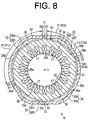
- FIG. 8 An electric type compressor for a vehicle air conditioning apparatus according to a seventh preferred embodiment of the present invention will now be described with reference to FIG. 8 .
- the seventh embodiment only different aspects from the sixth embodiment are described. Identical reference numerals to the sixth embodiment are applied to the same or corresponding members in the seventh embodiment and overlapped description is omitted.
- a plurality of recesses 17 is set in such a manner that length in the circumferential direction of some of the recesses 17 becomes smaller than that of the other recesses 17.
- the number of the recesses 17, which is formed in the stator core 16, is four, and two of the recesses 17 in the four recesses 17 are smaller in length in the circumferential direction than the other two recesses 17. Therefore, the protrusion 31 of the stator core 16, that is, the contacting portion 33 between the circumferential wall 25 and the stator core 16 is arranged at intervals of an unequal angle around the axis L. Thereby, some of the pitches P between the contacting portions 33, which are located next to each other, is different from the other pitches P.
- pitches P1 are larger than pitches P2.
- the elastic part 25d whose pitch P1 between the contacting portions 33 is relatively large, it is difficult that the elastic part 25d, whose pitch P2 between the contacting portions 33 is relatively small, elastically deforms.
- the compressor housing 11 or the circumferential wall 25 is made of the aluminum and the stator core 16 is made of silicone steel, whose thermal expansion coefficient is different from that of the aluminum.
- the compressor housing 11, whose thermal expansion coefficient is different from the stator core 16, is made of metallic material other than the aluminum.
- the compressor housing 11 is made of resin material.
- the thermal expansion coefficient of the compressor housing 11 or the circumferential wall 25 is differentiated from that of the stator core 16 in such a manner that when the temperature of the electric type compressor becomes relatively low, the compressor housing 11 and the stator core 16 shrink so as to tightly fit each other. That is, the thermal expansion coefficient of the compressor housing 11 is larger than that of the stator core 16.
- the thermal expansion coefficient of the compressor housing 11 is differentiated from that of the stator core 16 in such a manner that when the temperature of the electric type compressor becomes relatively high, the compressor housing 11 and the stator core 16 expand so as to tightly fit each other. That is, the compressor housing 11 is made of the material whose thermal expansion coefficient is smaller than that of the stator core 16.
- the number of the voids 32 is six. In the third embodiment, the number of the voids 32 is three. In the fourth, sixth and seventh embodiments, the number of the voids 32 is four. In the fifth embodiment, the number of the voids 32 is five. However, the number of the voids 32 is not limited to three through six. In alternative embodiments to the above-described embodiments, the number of the voids 32 is one, two, seven or more than seven.
- a plurality of the voids 32 is provided in such a manner that the contacting portions 33 between the circumferential wall 25 and the stator core 16 are arranged at intervals of an equal angle around the axis L
- the plurality of voids 32 is provided in such a manner that the contacting portions 33 between the circumferential wall 25 and the stator core 16 are arranged at intervals of an unequal angle around the axis L. In this case, the above-described effect (15) is substantially obtained.
- the coil 15 is distributively wound around the teeth 16b. In alternative embodiments to the second embodiment through the seventh embodiment, the coil 15 is intensively wound around the teeth 16b.
- the first void element 32a which is provided by forming the recess 36 in the inner circumferential surface 25a of the circumferential wall 25, and the second void element 32b, which is provided by forming the recess 17 in the outer circumferential surface 16c of the stator core 16, are connected to each other in the radial direction of the stator core 16. Thereby, one void 32 is formed.
- the first void element 32a which is provided by forming the recess 36 in the inner circumferential surface 25a of the circumferential wall 25, and the second void element 32b, which is provided by forming the recess 17 in the outer circumferential surface 16c of the stator core 16, are separated from each other in the radial direction of the stator core 16.
- the first void element 32a and the second void element 32b are each individually formed. That is, in this case, the number of voids 32, which is provided around the axis L of the stator core 16, is eight.
- the compression mechanism C is changed to a compression mechanism other than a scroll type.
- the compression mechanism C is changed to a piston type, a vane type and a helical type.
- the above-described embodiments of the present invention are applied to the electric type compressor, which serves as an electric machine, formed by integrating the electric motor with the compression mechanism C, which serves as a rotary machine.
- the present invention is merely applied to an electric motor.
- An electric motor Includes a housing and a circular stator.
- the housing has an inner circumferential surface.
- the housing also has a first predetermined thermal expansion coefficient.
- the housing further has an elastic part.
- the stator core is pressed to an inside of the housing by tight fit.
- the stator core has an outer circumferential surface.
- the stator core also has a second predetermined thermal expansion coefficient that is different from the first predetermined thermal expansion coefficient.
- a void is defined between the inner circumferential surface and the outer circumferential surface so as to prevent the inner and the outer circumferential surfaces from contacting each other In a circular region.
Landscapes
- Engineering & Computer Science (AREA)
- Power Engineering (AREA)
- Mechanical Engineering (AREA)
- General Engineering & Computer Science (AREA)
- Compressor (AREA)
- Iron Core Of Rotating Electric Machines (AREA)
- Motor Or Generator Frames (AREA)
Claims (19)
- Moteur électrique comprenant un boîtier (11a) et un noyau de stator circulaire (16), le boîtier (11a) ayant une surface circonférentielle interne (25a), le boîtier (11a) ayant également un premier coefficient de dilation thermique prédéterminé, le boîtier (11a) ayant en outre une partie élastique (25d), le noyau de stator circulaire (16) étant comprimé sur un intérieur du boîtier (11a) par ajustement par serrage, le noyau de stator (16) ayant une surface circonférentielle externe (16c), le noyau de stator (16) ayant également un second coefficient de dilatation thermique prédéterminé qui est différent du premier coefficient de dilatation thermique prédéterminé,
un vide (32) est défini entre la surface circonférentielle interne (25a) et la surface circonférentielle externe (16c) afin d'empêcher les surfaces circonférentielles interne et externe (25a, 16c) d'être en contact entre elles dans une région circulaire, lorsque le boîtier (11a) et le noyau de stator (16) se dilatent ou se rétrécissent afin de s'ajuster par serrage entre eux en raison d'un différentiel entre les premier et second coefficients de dilatation thermique prédéterminés, la partie élastique (25d) qui correspond au vide (32) étant élastiquement déformée ;
le boîtier (11a) a une paroi circonférentielle cylindrique (25) ; et
on prévoit trois parties de contact (33) ou plus, où le noyau de stator (16) est supporté par la paroi circonférentielle (25) ;
caractérisé en ce que :le noyau de stator (16) comprend des saillies (31) entre les premiers évidements (17) et la paroi circonférentielle (25) du boîtier (11a) comprend des seconds évidements (36),dans lequel chaque partie de contact (33) comprend une surface d'extrémité distale (31a) de la saillie (31),dans lequel un premier élément de vide (32a) est prévu entre la paroi circonférentielle (25) et le noyau de stator (16) en formant le second évidement (36) dans la surface circonférentielle interne (25a) de la paroi circonférentielle (25) du boîtier (11a), le second évidement (36) étant formé en dilatant vers l'extérieur une partie de la partie élastique (25d) de la paroi circonférentielle (25), qui correspond au second évidement (36), dans la direction radiale du noyau de stator (16),dans lequel un second élément de vide (32b) est prévu entre la paroi circonférentielle (25) et le noyau de stator (16) en formant le premier évidement (17) dans la surface circonférentielle externe (16c) du noyau de stator (16),dans lequel le vide (32) comprend le premier élément de vide (32a) et le second élément de vide (32b), etdans lequel, dans une forme ondulée de la paroi circonférentielle (25) dans la direction circonférentielle du noyau de stator (16), laquelle forme ondulée est formée par la dilation vers l'extérieur de chacune des parties élastiques (25d), un sommet de chaque forme ondulée est agencé à intervalles d'un angle inégal autour d'un axe central (L) du noyau de stator (16). - Moteur électrique selon la revendication 1, dans lequel le premier coefficient de dilatation thermique prédéterminé est supérieur au second coefficient de dilatation thermique prédéterminé.
- Moteur électrique selon la revendication 1, dans lequel le premier coefficient de dilatation thermique prédéterminé est inférieur au second coefficient de dilatation thermique prédéterminé.
- Moteur électrique selon l'une quelconque des revendications 1 à 3, dans lequel le noyau de stator (16) a un l'axe central (L), le nombre de vides (32) étant pluriel, une pluralité de vides (32) étant prévue autour de l'axe central (L).
- Moteur électrique selon l'une quelconque des revendications 1 à 4, dans lequel le nombre de vides (32) est de trois ou supérieur à trois.
- Moteur électrique selon les revendications 4 ou 5, dans lequel le boîtier (11a) et le noyau de stator (16) ont une pluralité de parties de contact (33) entre eux, la pluralité de vides (32) étant prévue de sorte que la pluralité de parties de contact (33) sont agencées à intervalles d'un angle égal autour de l'axe central (L).
- Moteur électrique selon les revendications 4 ou 5, dans lequel le boîtier (11a) et le noyau de stator (16) ont une pluralité de parties de contact (33) entre eux, la pluralité de vides (32) étant prévue de sorte que la pluralité de parties de contact (33) sont agencées à intervalles d'un angle inégal autour de l'axe central (L).
- Moteur électrique selon la revendication 1, dans lequel le noyau de stator (16) a l'axe central (L), le premier évidement (17) dans la surface circonférentielle externe (16c) ayant une surface inférieure dans laquelle une région (17a) est positionnée au niveau des côtés opposés dans une direction circonférentielle du noyau de stator (16), au moins la région existant dans une première surface cylindrique imaginaire (S1), dont le centre est positionné sur l'axe central (L), la surface circonférentielle interne (25a) et la surface circonférentielle externe (16c) étant en contact entre elles dans une région de contact, la région de contact existant dans une seconde surface cylindrique imaginaire (S2), dont le centre est également positionné sur l'axe central (L), le différentiel radial entre les première et seconde surfaces cylindriques imaginaires (S1, S2) étant prédéterminé de sorte que le différentiel radial du rayon de la première surface cylindrique imaginaire (S1) sur le rayon de la seconde surface cylindrique imaginaire (S2) est approximativement de 5/1000 à 15/1000.
- Moteur électrique selon les revendications 1 ou 8, dans lequel une partie amincie (17b) dans la forme d'une surface concave est formée dans le premier évidement (17).
- Moteur électrique selon la revendication 1, dans lequel le second évidement (36) dans la surface circonférentielle interne (25a) est formé par la partie élastique (25d) formée vers l'extérieur dans une direction radiale du noyau de stator (16).
- Moteur électrique selon la revendication 10, dans lequel le noyau de stator (16) a l'axe central (L), le nombre de points où la partie élastique (25d) est dilatée vers l'extérieur dans la direction radiale étant de cinq ou moins de cinq autour de l'axe central (L) du noyau de stator (16).
- Moteur électrique selon la revendication 1, dans lequel le second évidement (36) dans la surface circonférentielle interne (25a) a une surface inférieure se présentant sous la forme d'une surface concave.
- Moteur électrique selon l'une quelconque des revendications 1 à 12, dans lequel le noyau de stator (16) a l'axe central (L), la surface circonférentielle interne (25a) et la surface circonférentielle externe (16c) étant en contact entre elles dans une région de contact, la région de contact existant dans une surface cylindrique imaginaire, dont le centre est positionné sur l'axe central, la région de contact ayant une première zone prédéterminée, la surface cylindrique imaginaire ayant la même longueur que le noyau de stator (16) dans la direction de l'axe central, la surface cylindrique imaginaire ayant également une région sans contact où la surface circonférentielle interne (25a) et la surface circonférentielle externe (16c) ne sont pas en contact entre elles, la région sans contact ayant une seconde zone prédéterminée, le vide (32) étant formé de sorte que la première zone prédéterminée devient inférieure à la seconde zone prédéterminée.
- Moteur électrique selon la revendication 13, dans lequel un rapport de la première zone prédéterminée sur la zone totale de la première zone prédéterminée et de la seconde zone prédéterminée est de 30% ou inférieur à 30 %.
- Moteur électrique selon l'une quelconque des revendications 1 à 14, comprenant en outre une bobine qui est un enroulement de stator concentré enroulé autour du noyau de stator (16).
- Moteur électrique selon l'une quelconque des revendications 1 à 14, comprenant en outre une bobine qui est enroulée, de manière distributive autour du noyau de stator (16).
- Moteur électrique selon l'une quelconque des revendications 1 à 16, dans lequel le boîtier (11a) est réalisé à partir d'aluminium et/ou d'alliage d'aluminium, le noyau de stator (16) étant réalisé avec un acier au silicone.
- Compresseur de type électrique comprend le moteur électrique (M) selon l'une quelconque des revendications 1 à 17 et un mécanisme de compression (C).
- Compresseur de type électrique selon la revendication 18, dans lequel le noyau de stator (16) a l'axe central (L), un premier espace (30a) et un second espace (30b) qui sont définis au niveau des côtés opposés de l'axe central (L) dans le boîtier (11a), le vide (32) interconnectant le premier espace (30a) avec le second espace (30b), le mécanisme de compression (C) étant placé du côté du premier espace (30a), une entrée du compresseur de type électrique, qui est formée à travers le boîtier (11a) afin de correspondre au second espace (30b), étant raccordée avec un tuyau externe (24), le vide (32) étant utilisé en tant que passage de gaz qui interconnecte le mécanisme de compression (C) avec l'entrée.
Applications Claiming Priority (4)
| Application Number | Priority Date | Filing Date | Title |
|---|---|---|---|
| JP2002213934 | 2002-07-23 | ||
| JP2002213934 | 2002-07-23 | ||
| JP2003189687A JP4036148B2 (ja) | 2002-07-23 | 2003-07-01 | 電動モータ及び電動コンプレッサ |
| JP2003189687 | 2003-07-01 |
Publications (3)
| Publication Number | Publication Date |
|---|---|
| EP1384893A2 EP1384893A2 (fr) | 2004-01-28 |
| EP1384893A3 EP1384893A3 (fr) | 2007-02-21 |
| EP1384893B1 true EP1384893B1 (fr) | 2018-11-28 |
Family
ID=30002383
Family Applications (1)
| Application Number | Title | Priority Date | Filing Date |
|---|---|---|---|
| EP03016419.8A Expired - Lifetime EP1384893B1 (fr) | 2002-07-23 | 2003-07-21 | Moteur électrique et compresseur hermétique |
Country Status (3)
| Country | Link |
|---|---|
| US (1) | US7164218B2 (fr) |
| EP (1) | EP1384893B1 (fr) |
| JP (1) | JP4036148B2 (fr) |
Cited By (2)
| Publication number | Priority date | Publication date | Assignee | Title |
|---|---|---|---|---|
| US11277044B2 (en) | 2015-08-27 | 2022-03-15 | Bitzer Kuehlmaschinenbau Gmbh | Compressor |
| EP4203269A4 (fr) * | 2020-09-29 | 2024-10-16 | Daikin Industries, Ltd. | Appareil de moteur, compresseur et appareil de réfrigération |
Families Citing this family (78)
| Publication number | Priority date | Publication date | Assignee | Title |
|---|---|---|---|---|
| JP4036148B2 (ja) * | 2002-07-23 | 2008-01-23 | 株式会社豊田自動織機 | 電動モータ及び電動コンプレッサ |
| WO2005025037A1 (fr) | 2003-09-04 | 2005-03-17 | Mitsubishi Denki Kabushiki Kaisha | Moteur de synchronisation de type aimant permanent et son procede de fabrication |
| DE102004007322A1 (de) * | 2004-02-14 | 2005-09-01 | Robert Bosch Gmbh | Statoranordnung für eine elektrische Maschine |
| JP4485262B2 (ja) * | 2004-06-14 | 2010-06-16 | アイチエレック株式会社 | 電動機の固定子 |
| JP2006027355A (ja) * | 2004-07-13 | 2006-02-02 | Nsk Ltd | 電動パワーステアリング装置 |
| JP4546213B2 (ja) * | 2004-10-21 | 2010-09-15 | 本田技研工業株式会社 | モータおよびモータを搭載した電動パワーステアリング装置 |
| JP2006191702A (ja) * | 2004-12-28 | 2006-07-20 | Aichi Elec Co | ステータ及び回転機 |
| JP2006262631A (ja) * | 2005-03-17 | 2006-09-28 | Matsushita Electric Ind Co Ltd | 電動機 |
| JP4644509B2 (ja) * | 2005-03-30 | 2011-03-02 | サンデン株式会社 | スクロール型流体機械 |
| JP2006288128A (ja) * | 2005-04-04 | 2006-10-19 | Hitachi Ltd | 電動機 |
| JP4449811B2 (ja) * | 2005-04-15 | 2010-04-14 | 株式会社豊田自動織機 | 電動コンプレッサ |
| GB2428903B (en) * | 2005-08-03 | 2009-10-07 | Imra Europ S A S Uk Res Ct | Salient pole electrical machine |
| JP4566868B2 (ja) * | 2005-09-08 | 2010-10-20 | 三菱電機株式会社 | 車両用回転電機 |
| JP4700492B2 (ja) * | 2005-12-28 | 2011-06-15 | アスモ株式会社 | モータ、及びモータの製造方法 |
| JP2007244150A (ja) * | 2006-03-10 | 2007-09-20 | Toyota Industries Corp | 電動モータ及び電動圧縮機 |
| JP5020537B2 (ja) * | 2006-05-10 | 2012-09-05 | 日産自動車株式会社 | 回転電機 |
| JP4857910B2 (ja) * | 2006-05-24 | 2012-01-18 | 株式会社豊田自動織機 | 電動モータ及び電動圧縮機 |
| JP2008067571A (ja) * | 2006-09-11 | 2008-03-21 | Jtekt Corp | モータ及び電動ポンプ |
| JP4928978B2 (ja) * | 2007-02-23 | 2012-05-09 | 三菱重工業株式会社 | 電動圧縮機 |
| JP5067022B2 (ja) * | 2007-06-04 | 2012-11-07 | 株式会社豊田自動織機 | 電動圧縮機 |
| DE102007033076A1 (de) † | 2007-07-13 | 2009-01-15 | Dr. Fritz Faulhaber Gmbh & Co. Kg | Elektrischer Kleinstantrieb sowie Rückschlusselement und Verfahren zu dessen Herstellung |
| JP2009044880A (ja) * | 2007-08-09 | 2009-02-26 | Jtekt Corp | モータ及び電動パワーステアリング装置 |
| JP2009112096A (ja) * | 2007-10-29 | 2009-05-21 | Toyota Industries Corp | ステータコアの固定方法および電動圧縮機 |
| JP4758484B2 (ja) * | 2008-01-24 | 2011-08-31 | ダイキン工業株式会社 | 圧縮機 |
| JP5381139B2 (ja) * | 2009-02-09 | 2014-01-08 | Jfeスチール株式会社 | 電動機 |
| JP2010213527A (ja) * | 2009-03-12 | 2010-09-24 | Daikin Ind Ltd | 固定子、モータ及び圧縮機 |
| BE1019030A5 (nl) * | 2009-08-03 | 2012-01-10 | Atlas Copco Airpower Nv | Turbocompressorsysteem. |
| JP2011043138A (ja) * | 2009-08-24 | 2011-03-03 | Sanyo Electric Co Ltd | 圧縮機 |
| CN102122868B (zh) * | 2010-01-08 | 2016-06-29 | 思博莫顿股份公司 | 电机定子及其制造方法 |
| WO2012090679A1 (fr) * | 2010-12-28 | 2012-07-05 | 三洋電機株式会社 | Moteur, véhicule électrique équipé dudit moteur, et procédé d'assemblage de moteur |
| WO2012105249A1 (fr) * | 2011-02-02 | 2012-08-09 | パナソニック株式会社 | Moteur et équipement électrique l'utilisant |
| KR20130035680A (ko) * | 2011-09-30 | 2013-04-09 | 삼성전기주식회사 | 스위치드 릴럭턴스 모터 |
| EP2768123B1 (fr) | 2011-10-06 | 2017-06-21 | Mitsubishi Electric Corporation | Moteur électrique |
| US8941282B2 (en) | 2012-03-05 | 2015-01-27 | Siemens Energy, Inc. | Turbine generator stator core attachment technique |
| US20130270828A1 (en) * | 2012-04-13 | 2013-10-17 | Hamilton Sundstrand Corporation | Housing for an electrical starter motor |
| CN104412491B (zh) * | 2012-06-25 | 2017-03-08 | 西门子公司 | 用于电机的定子布置 |
| CN102734171B (zh) * | 2012-07-03 | 2015-06-10 | 南京奥特佳新能源科技有限公司 | 商用涡旋式压缩机动平衡供油机构 |
| US9306432B2 (en) * | 2012-10-31 | 2016-04-05 | Hamilton Sundstrand Corporation | Stator cooling channel tolerant to localized blockage |
| FR2998340A1 (fr) * | 2012-11-19 | 2014-05-23 | Danfoss Commercial Compressors | Compresseur a spirale a vitesse variable. |
| JP2014180090A (ja) * | 2013-03-14 | 2014-09-25 | Mitsubishi Electric Corp | 回転電機の固定子、回転電機の固定子の製造方法及び回転電機 |
| JP6357365B2 (ja) | 2014-06-27 | 2018-07-11 | サンデンホールディングス株式会社 | 電動圧縮機 |
| JP6400389B2 (ja) * | 2014-08-29 | 2018-10-03 | 三菱重工サーマルシステムズ株式会社 | 密閉型電動圧縮機 |
| CZ2017121A3 (cs) * | 2014-10-22 | 2018-05-30 | Mitsubishi Electric Corporation | Kompresor a způsob výroby kompresoru |
| JP6290065B2 (ja) * | 2014-10-23 | 2018-03-07 | 三菱電機株式会社 | 圧縮機製造装置及び圧縮機製造方法 |
| DE102014226593A1 (de) * | 2014-12-19 | 2016-06-23 | Robert Bosch Gmbh | Elektromotor mit reduzierter Luftschallabstrahlung und Körperschallübertragung |
| CN105790455B (zh) * | 2014-12-26 | 2019-07-30 | 德昌电机(深圳)有限公司 | 内转子电机及其定子结构 |
| DE102015200621A1 (de) * | 2015-01-16 | 2016-07-21 | Magna powertrain gmbh & co kg | Stator für eine elektrische Maschine |
| GB201501579D0 (en) * | 2015-01-30 | 2015-03-18 | Nidec Sr Drives Ltd | A stator for an electrical machine |
| KR101940682B1 (ko) | 2015-04-07 | 2019-01-22 | 엘지이노텍 주식회사 | 스테이터 및 이를 포함하는 모터 |
| JP6394907B2 (ja) * | 2015-05-12 | 2018-09-26 | 株式会社豊田自動織機 | 電動圧縮機 |
| DE102015226720A1 (de) * | 2015-07-15 | 2017-01-19 | Brose Fahrzeugteile GmbH & Co. Kommanditgesellschaft, Würzburg | Elektrische Maschine |
| DE102015214788B4 (de) * | 2015-08-03 | 2025-01-02 | Hanon Systems Efp Deutschland Gmbh | Elektrischer Verdichter zum Verdichten eines Gases, insbesondere für ein Kraftfahrzeug |
| JP6607791B2 (ja) * | 2016-01-14 | 2019-11-20 | 三菱重工サーマルシステムズ株式会社 | モータ及び電動圧縮機 |
| JP2017180175A (ja) * | 2016-03-29 | 2017-10-05 | 三菱重工業株式会社 | 圧縮機 |
| WO2017175945A1 (fr) * | 2016-04-06 | 2017-10-12 | Lg Electronics Inc. | Compresseur actionné par moteur |
| JP7067880B2 (ja) * | 2017-07-26 | 2022-05-16 | 三菱重工サーマルシステムズ株式会社 | 圧縮機 |
| JP6842385B2 (ja) * | 2017-08-25 | 2021-03-17 | 三菱重工サーマルシステムズ株式会社 | スクロール圧縮機 |
| EP3742581A4 (fr) * | 2018-01-18 | 2021-01-20 | Mitsubishi Electric Corporation | Stator, moteur, ventilateur, aspirateur électrique et sèche-mains |
| GB2579357B (en) * | 2018-11-28 | 2021-10-06 | Jaguar Land Rover Ltd | A stator and stator housing |
| US11515750B2 (en) * | 2018-12-06 | 2022-11-29 | Steering Solutions Ip Holding Corporation | Permanent magnet machine stator |
| US11146125B2 (en) * | 2018-12-06 | 2021-10-12 | Steering Solutions Ip Holding Corporation | Permanent magnet machine |
| CN111641276B (zh) * | 2019-03-01 | 2026-05-01 | 谷轮环境科技(苏州)有限公司 | 定子以及包括其的电机和压缩机 |
| JP7226088B2 (ja) | 2019-05-21 | 2023-02-21 | 株式会社デンソー | ステータアセンブリ、及び、モータ |
| JP7167849B2 (ja) | 2019-05-21 | 2022-11-09 | 株式会社デンソー | ステータアセンブリ、及び、モータ |
| DE102019122239A1 (de) * | 2019-08-19 | 2021-02-25 | Wittenstein Se | Stator |
| EP4109719B1 (fr) * | 2020-02-20 | 2025-11-19 | NISSAN MOTOR Co., Ltd. | Machine dynamo-électrique et sa structure de montage sur un véhicule |
| CN111509876B (zh) * | 2020-05-27 | 2025-04-25 | 精进电动科技股份有限公司 | 一种定子铁芯冷却结构及电机冷却系统 |
| ES3033089T3 (en) * | 2020-06-30 | 2025-07-30 | Daikin Ind Ltd | Compressor |
| JP7125637B1 (ja) * | 2021-03-16 | 2022-08-25 | ダイキン工業株式会社 | 圧縮装置及び冷凍装置 |
| JP7596948B2 (ja) * | 2021-06-18 | 2024-12-10 | 株式会社デンソー | モータ |
| CN113794290B (zh) * | 2021-09-13 | 2022-12-20 | 珠海格力节能环保制冷技术研究中心有限公司 | 电机、压缩机、空调器 |
| CN116418156A (zh) * | 2021-12-31 | 2023-07-11 | 安徽威灵汽车部件有限公司 | 电机及具有该电机的车辆 |
| FR3137514A1 (fr) * | 2022-06-29 | 2024-01-05 | Valeo Equipements Electriques Moteur | Ensemble stator et carter à résonance réduite |
| JP2024046195A (ja) * | 2022-09-22 | 2024-04-03 | サンデン株式会社 | 電動圧縮機 |
| DE102023102466A1 (de) | 2023-02-01 | 2024-08-01 | Dr. Ing. H.C. F. Porsche Aktiengesellschaft | Elektrische Maschine, Herstellung und Verwendung derselben sowie Kraftfahrzeug mit einer solchen Maschine |
| US12562616B2 (en) * | 2023-06-15 | 2026-02-24 | Mcmillan Electric Company | Motor with expandable casing |
| JP2025044381A (ja) * | 2023-09-20 | 2025-04-02 | 株式会社ミクニ | 永久磁石埋込型モータ及びポンプ装置 |
| FR3154560A1 (fr) * | 2023-10-18 | 2025-04-25 | Valeo Systèmes D’Essuyage | Ensemble pour moteur électrique à stator et carter de protection améliorés |
Family Cites Families (17)
| Publication number | Priority date | Publication date | Assignee | Title |
|---|---|---|---|---|
| DE740531C (de) * | 1939-06-29 | 1943-10-26 | Licht Und Kraft Ag | Einrichtung zur Verminderung der Gefahr einer Bildung von Schrumpfrissen in dem um das Staenderblechpaket elektrischer Maschinen herumgegossenen Leichtmetallgehaeuse |
| DE2042239A1 (de) * | 1970-08-26 | 1972-03-02 | Siemens Ag | Elektrische Maschine mit nngbe wickeltem Standerpaket |
| US4250423A (en) * | 1978-08-25 | 1981-02-10 | Sundstrand Corporation | Generator with stator retention |
| JPS57129287A (en) * | 1981-02-04 | 1982-08-11 | Hitachi Ltd | Enclosed compressor |
| GB8800813D0 (en) * | 1988-01-14 | 1988-02-17 | Lucas Ind Plc | Rotary electric machine |
| US5218252A (en) * | 1992-02-11 | 1993-06-08 | Sundstrand Corporation | Dynamoelectric machines with stator positioning |
| US5331238A (en) * | 1993-03-01 | 1994-07-19 | Sundstrand Corporation | Apparatus for containment and cooling of a core within a housing |
| JPH1127878A (ja) * | 1997-06-30 | 1999-01-29 | Mitsubishi Heavy Ind Ltd | モータ |
| US6000917A (en) * | 1997-11-06 | 1999-12-14 | American Standard Inc. | Control of suction gas and lubricant flow in a scroll compressor |
| JP3855504B2 (ja) * | 1998-12-14 | 2006-12-13 | 株式会社デンソー | 密閉型電動圧縮機 |
| DE19960088A1 (de) * | 1999-12-14 | 2001-03-15 | Daimler Chrysler Ag | Elektrische Maschine mit einem Gehäuse |
| JP4592143B2 (ja) * | 2000-04-06 | 2010-12-01 | パナソニック株式会社 | 圧縮機および電動機 |
| WO2002031947A1 (fr) * | 2000-10-12 | 2002-04-18 | Matsushita Electric Industrial Co., Ltd. | Moteur electrique |
| JP3661589B2 (ja) * | 2000-11-21 | 2005-06-15 | 日産自動車株式会社 | モータまたは発電機 |
| JP4036148B2 (ja) * | 2002-07-23 | 2008-01-23 | 株式会社豊田自動織機 | 電動モータ及び電動コンプレッサ |
| JP2004201428A (ja) * | 2002-12-19 | 2004-07-15 | Matsushita Electric Ind Co Ltd | 電動機 |
| JP4269907B2 (ja) * | 2003-11-21 | 2009-05-27 | 株式会社豊田自動織機 | 密閉型電動圧縮機におけるステータコアの組み付け方法 |
-
2003
- 2003-07-01 JP JP2003189687A patent/JP4036148B2/ja not_active Expired - Lifetime
- 2003-07-21 EP EP03016419.8A patent/EP1384893B1/fr not_active Expired - Lifetime
- 2003-07-22 US US10/624,854 patent/US7164218B2/en not_active Expired - Lifetime
Non-Patent Citations (1)
| Title |
|---|
| None * |
Cited By (2)
| Publication number | Priority date | Publication date | Assignee | Title |
|---|---|---|---|---|
| US11277044B2 (en) | 2015-08-27 | 2022-03-15 | Bitzer Kuehlmaschinenbau Gmbh | Compressor |
| EP4203269A4 (fr) * | 2020-09-29 | 2024-10-16 | Daikin Industries, Ltd. | Appareil de moteur, compresseur et appareil de réfrigération |
Also Published As
| Publication number | Publication date |
|---|---|
| JP4036148B2 (ja) | 2008-01-23 |
| US20040124731A1 (en) | 2004-07-01 |
| JP2004112988A (ja) | 2004-04-08 |
| US7164218B2 (en) | 2007-01-16 |
| EP1384893A2 (fr) | 2004-01-28 |
| EP1384893A3 (fr) | 2007-02-21 |
Similar Documents
| Publication | Publication Date | Title |
|---|---|---|
| US7164218B2 (en) | Electric motor and electric type compressor | |
| US7538468B2 (en) | Electric motor and electric compressor with improved housing and stator | |
| EP1533527B1 (fr) | Méthode d'assemblage d'un boîtier de moteur et d'un stator de moteur d'un compresseur de type hermétique | |
| US9413204B2 (en) | Motor-driven compressor | |
| JP2011055576A (ja) | 圧縮機 | |
| US10738780B2 (en) | Electric compressor | |
| US7938633B2 (en) | Electric compressor and electric motor with a housing having a circumferential wall with thick and thin portions | |
| KR102850958B1 (ko) | 모터 및 이를 포함하는 압축기 | |
| EP1471256B1 (fr) | Compresseur hermetique | |
| US6776592B2 (en) | Scroll type compressor | |
| JPWO2016199884A1 (ja) | 電動圧縮機 | |
| JP2013068187A (ja) | 電動圧縮機 | |
| JP2010041851A (ja) | 固定子とケーシングとの固定構造及びそれを備えた圧縮機 | |
| KR102097499B1 (ko) | 스크롤형 압축기 | |
| US7459810B2 (en) | Stator of linear motor | |
| JP2008206342A (ja) | モータ回転子およびそれを用いた圧縮機 | |
| US20030068246A1 (en) | Compressor | |
| JP5807149B2 (ja) | 流体機械及び流体機械のステータ固定方法 | |
| KR20210093086A (ko) | 전동식 압축기 | |
| KR20220092067A (ko) | 전동기 및 이를 구비한 밀폐형 압축기 | |
| US20250274018A1 (en) | Electric compressor | |
| WO2024262231A1 (fr) | Compresseur électrique à onduleur intégré | |
| JP2026001142A5 (fr) | ||
| JP4379075B2 (ja) | 圧縮機 | |
| WO2026033905A1 (fr) | Moteur de compresseur électrique |
Legal Events
| Date | Code | Title | Description |
|---|---|---|---|
| PUAI | Public reference made under article 153(3) epc to a published international application that has entered the european phase |
Free format text: ORIGINAL CODE: 0009012 |
|
| 17P | Request for examination filed |
Effective date: 20030721 |
|
| AK | Designated contracting states |
Kind code of ref document: A2 Designated state(s): AT BE BG CH CY CZ DE DK EE ES FI FR GB GR HU IE IT LI LU MC NL PT RO SE SI SK TR |
|
| AX | Request for extension of the european patent |
Extension state: AL LT LV MK |
|
| RIC1 | Information provided on ipc code assigned before grant |
Ipc: F04C 18/02 20060101ALI20060725BHEP Ipc: F04C 23/00 20060101AFI20030929BHEP Ipc: F04C 29/04 20060101ALI20060725BHEP Ipc: H02K 1/18 20060101ALI20060725BHEP |
|
| PUAL | Search report despatched |
Free format text: ORIGINAL CODE: 0009013 |
|
| AK | Designated contracting states |
Kind code of ref document: A3 Designated state(s): AT BE BG CH CY CZ DE DK EE ES FI FR GB GR HU IE IT LI LU MC NL PT RO SE SI SK TR |
|
| AX | Request for extension of the european patent |
Extension state: AL LT LV MK |
|
| AKX | Designation fees paid |
Designated state(s): DE FR IT |
|
| 17Q | First examination report despatched |
Effective date: 20110211 |
|
| GRAP | Despatch of communication of intention to grant a patent |
Free format text: ORIGINAL CODE: EPIDOSNIGR1 |
|
| RIC1 | Information provided on ipc code assigned before grant |
Ipc: H02K 7/14 20060101ALI20180524BHEP Ipc: F04C 18/02 20060101ALI20180524BHEP Ipc: F04C 28/28 20060101ALI20180524BHEP Ipc: F04C 29/04 20060101ALI20180524BHEP Ipc: H02K 5/04 20060101ALI20180524BHEP Ipc: F04C 23/00 19680901AFI20180524BHEP Ipc: H02K 1/14 20060101ALI20180524BHEP Ipc: H02K 1/18 20060101ALI20180524BHEP |
|
| INTG | Intention to grant announced |
Effective date: 20180608 |
|
| GRAS | Grant fee paid |
Free format text: ORIGINAL CODE: EPIDOSNIGR3 |
|
| GRAA | (expected) grant |
Free format text: ORIGINAL CODE: 0009210 |
|
| AK | Designated contracting states |
Kind code of ref document: B1 Designated state(s): DE FR IT |
|
| REG | Reference to a national code |
Ref country code: DE Ref legal event code: R096 Ref document number: 60351662 Country of ref document: DE |
|
| RIC2 | Information provided on ipc code assigned after grant |
Ipc: H02K 1/14 20060101ALI20180524BHEP Ipc: H02K 5/04 20060101ALI20180524BHEP Ipc: F04C 28/28 20060101ALI20180524BHEP Ipc: F04C 18/02 20060101ALI20180524BHEP Ipc: F04C 29/04 20060101ALI20180524BHEP Ipc: H02K 7/14 20060101ALI20180524BHEP Ipc: F04C 23/00 20060101AFI20180524BHEP Ipc: H02K 1/18 20060101ALI20180524BHEP |
|
| PG25 | Lapsed in a contracting state [announced via postgrant information from national office to epo] |
Ref country code: IT Free format text: LAPSE BECAUSE OF FAILURE TO SUBMIT A TRANSLATION OF THE DESCRIPTION OR TO PAY THE FEE WITHIN THE PRESCRIBED TIME-LIMIT Effective date: 20181128 |
|
| REG | Reference to a national code |
Ref country code: DE Ref legal event code: R097 Ref document number: 60351662 Country of ref document: DE |
|
| PLBE | No opposition filed within time limit |
Free format text: ORIGINAL CODE: 0009261 |
|
| STAA | Information on the status of an ep patent application or granted ep patent |
Free format text: STATUS: NO OPPOSITION FILED WITHIN TIME LIMIT |
|
| 26N | No opposition filed |
Effective date: 20190829 |
|
| PG25 | Lapsed in a contracting state [announced via postgrant information from national office to epo] |
Ref country code: FR Free format text: LAPSE BECAUSE OF NON-PAYMENT OF DUE FEES Effective date: 20190731 |
|
| PGFP | Annual fee paid to national office [announced via postgrant information from national office to epo] |
Ref country code: DE Payment date: 20220531 Year of fee payment: 20 |
|
| P01 | Opt-out of the competence of the unified patent court (upc) registered |
Effective date: 20230519 |
|
| REG | Reference to a national code |
Ref country code: DE Ref legal event code: R071 Ref document number: 60351662 Country of ref document: DE |