EP1533527B1 - Méthode d'assemblage d'un boîtier de moteur et d'un stator de moteur d'un compresseur de type hermétique - Google Patents
Méthode d'assemblage d'un boîtier de moteur et d'un stator de moteur d'un compresseur de type hermétique Download PDFInfo
- Publication number
- EP1533527B1 EP1533527B1 EP04027475A EP04027475A EP1533527B1 EP 1533527 B1 EP1533527 B1 EP 1533527B1 EP 04027475 A EP04027475 A EP 04027475A EP 04027475 A EP04027475 A EP 04027475A EP 1533527 B1 EP1533527 B1 EP 1533527B1
- Authority
- EP
- European Patent Office
- Prior art keywords
- motor housing
- stator core
- portions
- fastening
- fastening interference
- Prior art date
- Legal status (The legal status is an assumption and is not a legal conclusion. Google has not performed a legal analysis and makes no representation as to the accuracy of the status listed.)
- Expired - Lifetime
Links
- 238000000034 method Methods 0.000 title claims description 27
- XEEYBQQBJWHFJM-UHFFFAOYSA-N Iron Chemical compound [Fe] XEEYBQQBJWHFJM-UHFFFAOYSA-N 0.000 claims description 16
- 238000003825 pressing Methods 0.000 claims description 13
- 229910052742 iron Inorganic materials 0.000 claims description 8
- 229910052782 aluminium Inorganic materials 0.000 claims description 7
- XAGFODPZIPBFFR-UHFFFAOYSA-N aluminium Chemical compound [Al] XAGFODPZIPBFFR-UHFFFAOYSA-N 0.000 claims description 7
- 238000001816 cooling Methods 0.000 claims description 5
- 238000005242 forging Methods 0.000 claims description 3
- 239000000463 material Substances 0.000 claims description 3
- 229910052751 metal Inorganic materials 0.000 claims 1
- 239000002184 metal Substances 0.000 claims 1
- CURLTUGMZLYLDI-UHFFFAOYSA-N Carbon dioxide Chemical compound O=C=O CURLTUGMZLYLDI-UHFFFAOYSA-N 0.000 description 14
- 239000003507 refrigerant Substances 0.000 description 14
- 229910002092 carbon dioxide Inorganic materials 0.000 description 7
- 239000001569 carbon dioxide Substances 0.000 description 7
- 230000004048 modification Effects 0.000 description 5
- 238000012986 modification Methods 0.000 description 5
- KYKAJFCTULSVSH-UHFFFAOYSA-N chloro(fluoro)methane Chemical compound F[C]Cl KYKAJFCTULSVSH-UHFFFAOYSA-N 0.000 description 3
- 230000006835 compression Effects 0.000 description 3
- 238000007906 compression Methods 0.000 description 3
- 238000005266 casting Methods 0.000 description 1
- 230000000694 effects Effects 0.000 description 1
- 230000005489 elastic deformation Effects 0.000 description 1
- 238000004519 manufacturing process Methods 0.000 description 1
- 239000007769 metal material Substances 0.000 description 1
Images


Classifications
-
- F—MECHANICAL ENGINEERING; LIGHTING; HEATING; WEAPONS; BLASTING
- F04—POSITIVE - DISPLACEMENT MACHINES FOR LIQUIDS; PUMPS FOR LIQUIDS OR ELASTIC FLUIDS
- F04C—ROTARY-PISTON, OR OSCILLATING-PISTON, POSITIVE-DISPLACEMENT MACHINES FOR LIQUIDS; ROTARY-PISTON, OR OSCILLATING-PISTON, POSITIVE-DISPLACEMENT PUMPS
- F04C29/00—Component parts, details or accessories of pumps or pumping installations, not provided for in groups F04C18/00 - F04C28/00
- F04C29/0042—Driving elements, brakes, couplings, transmissions specially adapted for pumps
- F04C29/0085—Prime movers
-
- B—PERFORMING OPERATIONS; TRANSPORTING
- B21—MECHANICAL METAL-WORKING WITHOUT ESSENTIALLY REMOVING MATERIAL; PUNCHING METAL
- B21K—MAKING FORGED OR PRESSED METAL PRODUCTS, e.g. HORSE-SHOES, RIVETS, BOLTS OR WHEELS
- B21K1/00—Making machine elements
- B21K1/26—Making machine elements housings or supporting parts, e.g. axle housings, engine mountings
-
- F—MECHANICAL ENGINEERING; LIGHTING; HEATING; WEAPONS; BLASTING
- F01—MACHINES OR ENGINES IN GENERAL; ENGINE PLANTS IN GENERAL; STEAM ENGINES
- F01C—ROTARY-PISTON OR OSCILLATING-PISTON MACHINES OR ENGINES
- F01C21/00—Component parts, details or accessories not provided for in groups F01C1/00 - F01C20/00
- F01C21/10—Outer members for co-operation with rotary pistons; Casings
-
- F—MECHANICAL ENGINEERING; LIGHTING; HEATING; WEAPONS; BLASTING
- F04—POSITIVE - DISPLACEMENT MACHINES FOR LIQUIDS; PUMPS FOR LIQUIDS OR ELASTIC FLUIDS
- F04C—ROTARY-PISTON, OR OSCILLATING-PISTON, POSITIVE-DISPLACEMENT MACHINES FOR LIQUIDS; ROTARY-PISTON, OR OSCILLATING-PISTON, POSITIVE-DISPLACEMENT PUMPS
- F04C23/00—Combinations of two or more pumps, each being of rotary-piston or oscillating-piston type, specially adapted for elastic fluids; Pumping installations specially adapted for elastic fluids; Multi-stage pumps specially adapted for elastic fluids
- F04C23/008—Hermetic pumps
-
- F—MECHANICAL ENGINEERING; LIGHTING; HEATING; WEAPONS; BLASTING
- F04—POSITIVE - DISPLACEMENT MACHINES FOR LIQUIDS; PUMPS FOR LIQUIDS OR ELASTIC FLUIDS
- F04C—ROTARY-PISTON, OR OSCILLATING-PISTON, POSITIVE-DISPLACEMENT MACHINES FOR LIQUIDS; ROTARY-PISTON, OR OSCILLATING-PISTON, POSITIVE-DISPLACEMENT PUMPS
- F04C23/00—Combinations of two or more pumps, each being of rotary-piston or oscillating-piston type, specially adapted for elastic fluids; Pumping installations specially adapted for elastic fluids; Multi-stage pumps specially adapted for elastic fluids
- F04C23/02—Pumps characterised by combination with, or adaptation to, specific driving engines or motors
-
- H—ELECTRICITY
- H02—GENERATION; CONVERSION OR DISTRIBUTION OF ELECTRIC POWER
- H02K—DYNAMO-ELECTRIC MACHINES
- H02K1/00—Details of the magnetic circuit
- H02K1/06—Details of the magnetic circuit characterised by the shape, form or construction
- H02K1/12—Stationary parts of the magnetic circuit
- H02K1/18—Means for mounting or fastening magnetic stationary parts on to, or to, the stator structures
-
- H—ELECTRICITY
- H02—GENERATION; CONVERSION OR DISTRIBUTION OF ELECTRIC POWER
- H02K—DYNAMO-ELECTRIC MACHINES
- H02K41/00—Propulsion systems in which a rigid body is moved along a path due to dynamo-electric interaction between the body and a magnetic field travelling along the path
- H02K41/06—Rolling motors, i.e. motors having the rotor axis parallel to the stator axis and following a circular path as the rotor rolls around the inside or outside of the stator ; Nutating motors, i.e. having the rotor axis parallel to the stator axis inclined with respect to the stator axis and performing a nutational movement as the rotor rolls on the stator
-
- H—ELECTRICITY
- H02—GENERATION; CONVERSION OR DISTRIBUTION OF ELECTRIC POWER
- H02K—DYNAMO-ELECTRIC MACHINES
- H02K5/00—Casings; Enclosures; Supports
- H02K5/02—Casings or enclosures characterised by the material thereof
-
- H—ELECTRICITY
- H02—GENERATION; CONVERSION OR DISTRIBUTION OF ELECTRIC POWER
- H02K—DYNAMO-ELECTRIC MACHINES
- H02K5/00—Casings; Enclosures; Supports
- H02K5/04—Casings or enclosures characterised by the shape, form or construction thereof
-
- F—MECHANICAL ENGINEERING; LIGHTING; HEATING; WEAPONS; BLASTING
- F04—POSITIVE - DISPLACEMENT MACHINES FOR LIQUIDS; PUMPS FOR LIQUIDS OR ELASTIC FLUIDS
- F04C—ROTARY-PISTON, OR OSCILLATING-PISTON, POSITIVE-DISPLACEMENT MACHINES FOR LIQUIDS; ROTARY-PISTON, OR OSCILLATING-PISTON, POSITIVE-DISPLACEMENT PUMPS
- F04C2230/00—Manufacture
- F04C2230/60—Assembly methods
-
- F—MECHANICAL ENGINEERING; LIGHTING; HEATING; WEAPONS; BLASTING
- F04—POSITIVE - DISPLACEMENT MACHINES FOR LIQUIDS; PUMPS FOR LIQUIDS OR ELASTIC FLUIDS
- F04C—ROTARY-PISTON, OR OSCILLATING-PISTON, POSITIVE-DISPLACEMENT MACHINES FOR LIQUIDS; ROTARY-PISTON, OR OSCILLATING-PISTON, POSITIVE-DISPLACEMENT PUMPS
- F04C2240/00—Components
- F04C2240/10—Stators
-
- Y—GENERAL TAGGING OF NEW TECHNOLOGICAL DEVELOPMENTS; GENERAL TAGGING OF CROSS-SECTIONAL TECHNOLOGIES SPANNING OVER SEVERAL SECTIONS OF THE IPC; TECHNICAL SUBJECTS COVERED BY FORMER USPC CROSS-REFERENCE ART COLLECTIONS [XRACs] AND DIGESTS
- Y10—TECHNICAL SUBJECTS COVERED BY FORMER USPC
- Y10T—TECHNICAL SUBJECTS COVERED BY FORMER US CLASSIFICATION
- Y10T29/00—Metal working
- Y10T29/49—Method of mechanical manufacture
- Y10T29/49002—Electrical device making
- Y10T29/49009—Dynamoelectric machine
-
- Y—GENERAL TAGGING OF NEW TECHNOLOGICAL DEVELOPMENTS; GENERAL TAGGING OF CROSS-SECTIONAL TECHNOLOGIES SPANNING OVER SEVERAL SECTIONS OF THE IPC; TECHNICAL SUBJECTS COVERED BY FORMER USPC CROSS-REFERENCE ART COLLECTIONS [XRACs] AND DIGESTS
- Y10—TECHNICAL SUBJECTS COVERED BY FORMER USPC
- Y10T—TECHNICAL SUBJECTS COVERED BY FORMER US CLASSIFICATION
- Y10T29/00—Metal working
- Y10T29/49—Method of mechanical manufacture
- Y10T29/49002—Electrical device making
- Y10T29/49009—Dynamoelectric machine
- Y10T29/49012—Rotor
-
- Y—GENERAL TAGGING OF NEW TECHNOLOGICAL DEVELOPMENTS; GENERAL TAGGING OF CROSS-SECTIONAL TECHNOLOGIES SPANNING OVER SEVERAL SECTIONS OF THE IPC; TECHNICAL SUBJECTS COVERED BY FORMER USPC CROSS-REFERENCE ART COLLECTIONS [XRACs] AND DIGESTS
- Y10—TECHNICAL SUBJECTS COVERED BY FORMER USPC
- Y10T—TECHNICAL SUBJECTS COVERED BY FORMER US CLASSIFICATION
- Y10T29/00—Metal working
- Y10T29/53—Means to assemble or disassemble
- Y10T29/5313—Means to assemble electrical device
- Y10T29/53143—Motor or generator
Definitions
- the present invention relates to a method of assembling a sealed type motor-driven compressor.
- a sealed housing accommodates, for example, a scroll type compressor mechanism and an electrical motor for driving the mechanism.
- the motor includes a rotational shaft, a rotor, and a stator.
- the rotational shaft of the motor is rotationally supported at a middle portion of a motor housing, which forms part of the sealed housing.
- the rotor is securely fitted to the outer circumferential surface of the rotational shaft.
- the stator is securely fitted to the inner circumferential surface of the motor housing through shrink fitting.
- the stator includes a cylindrical stator core and coils arranged along the inner circumference of the stator core.
- chlorofluorocarbon or carbon dioxide is used as refrigerant gas charged in a refrigerating circuit of a vehicle air conditioner.
- the maximum charging pressure of chlorofluorocarbon gas is approximately 1 to 2 MPa, while that of carbon dioxide is equal to or greater than 10 MPa.
- the pressure in the motor housing is maximally 1 to 2 MPa, the stator is prevented from loosening with respect to the motor housing by a fastening interference defined in shrink fitting of the stator core and the motor housing.
- carbon dioxide is used as the refrigerant, the pressure equal to or greater than 10 MPa is applied to the motor housing.
- the motor housing must have a relatively large wall thickness for preventing the increase of the inner diameter of the motor housing.
- this increases the dimensions and weight of the compressor.
- the shrink fitting of the stator core and the motor housing may be performed with a sufficiently large fastening interference such that an effective fastening interference is maintained even if the inner circumference of the motor housing is increased.
- the shrink fitting must be performed at a relatively high temperature, leading to lowering of the strength of the motor housing, which is formed of aluminum. It is thus extremely difficult to increase the fastening interference for the shrink fitting.
- the motor housing is formed of iron
- the motor housing formed of iron increases the weight of the compressor.
- Japanese Patent Publication JP 05 268740 discloses a combination of features falling within the scope of the precharacterising portion of Claim 1.
- a method of assembling a sealed type motor-driven compressor having a cylindrical motor housing and an annular stator core fastened to the interior of the motor housing the method being characterized by: mechanically deforming the motor housing in an elastic manner for permitting the stator core to be inserted into the motor housing; and restoring the deformed motor housing to the original shape by an elastic shape-restoring force with the stator core inserted into the motor housing, such that the motor housing fastens the stator core.
- the compressor 10 includes a sealed housing 11 having a housing body 12 and a front housing 13.
- the housing body 12 is formed of aluminum through forging and has a lidded, horizontal cylindrical shape.
- the front housing 13 is securely connected to a front opening end (as viewed to the right in Fig. 1) of the housing body 12.
- the housing body 12 includes a compressor housing 14, a motor housing 15, and a rear housing 16 (as viewed to the left in Fig. 1).
- the compressor housing 14 is located in a front portion of the housing body 12.
- the motor housing 15 has a relatively small diameter and is formed integrally with a rear end of the compressor housing 14.
- the rear housing 16 is formed integrally with a rear end of the motor housing 15.
- the compressor housing 14 accommodates a scroll type compressor mechanism 17.
- the mechanism 17 includes a base plate 18, a fixed scroll 19, and a revolving scroll 20.
- the base plate 18 is securely fitted to a stepped portion of an inner circumferential surface 14a of the compressor housing 14.
- the fixed scroll 19 is securely fitted to the inner circumferential surface of a front opening of the compressor housing 14.
- the revolving scroll 20 is arranged between the base plate 18 and the fixed scroll 19.
- a compression chamber 21) is defined by the fixed scroll 19 and the revolving scroll 20.
- a suction chamber 22 is defined in the compressor housing 14 and at a rear side of the base plate 18.
- a discharge chamber 23 is defined in the front housing 13. Refrigerant gas is drawn from the suction chamber 22 to the compression chamber 21 through a suction port 18a, which is defined in the base plate 18, and is compressed in the compression chamber 21. The refrigerant gas is then discharged to the discharge chamber 23 through a discharge port 19a, which is defined in the fixed scroll 19.
- the refrigerant gas is, for example, carbon dioxide.
- An outlet 13a is defined in the front housing 13 for supplying the compressed refrigerant gas to an external refrigerating circuit.
- An inlet 16a is defined in the rear housing 16 for introducing the refrigerant gas from the external refrigerating circuit to the suction chamber 22.
- a stator 31 is securely fitted to the inner circumferential surface of the motor housing 15, which forms part of an electrical motor M.
- the stator 31 includes a stator core 32, teeth 32a, and coils 33.
- the stator core 32 is formed of iron.
- the teeth 32a are formed on the inner circumference of the stator core 32 and the coils 33 are each wound around the corresponding one of the teeth 32a.
- a boss portion 16b is formed integrally with an inner rear side of the rear housing 16.
- a boss portion 18b is formed integrally with the rear side of the base plate 18.
- a rotary shaft 28 is rotationally supported by a pair of bearings 29, 30 between the boss portions 16b, 18b.
- An eccentric pin 34 is disposed at a distal end of the rotary shaft 28 and is connected to a boss portion 20a, which is formed integrally with a rear side of the revolving scroll 20, through a bearing.
- a rotor 35 is securely fitted to the outer circumferential surface of the rotary shaft 28.
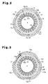
- Fig. 2 is a lateral cross-sectional view showing the motor housing 15 and the stator core 32.
- the motor housing 15 includes first, second, and third expanded portions 15b, 15c, 15d and first, second, and third fastening interference portions 15e, 15f, 15g.
- Each of the fastening interference portions 15e to 15g is formed integrally with the motor housing 15 and is arranged between the corresponding adjacent ones of the first to third expanded portions 15b to 15d.
- First, second, and third fastening surfaces S1, S2, S3 are each formed along the arched inner circumferential surface of the corresponding one of the first to third fastening interference portions 15e to 15g.
- the first to third fastening surfaces S1 to S3 are fastened to an outer circumferential surface 32b of the stator core 32 at three respective positions by a predetermined fastening force.
- the stator core 32 is assembled with the motor housing 15 by the following method.
- Fig. 3 shows the state of the motor housing 15 and the stator core 32 before assembly.
- the first to third fastening surfaces S1 to S3 of the first to third fastening interference portions 15e to 15g are located radially inward compared to the outer circumferential surface 32b of the stator core 32.
- the distance between the outer circumferential surface 32b of the stator core 32 and each of the fastening surfaces S1 to S3, as viewed with respect to the axis of the stator core 32, is defined as a fastening interference ⁇ .
- the fastening interference ⁇ is set to, for example, 200 ⁇ m.
- the second and third expanded portions 15c, 15d are received by a lower pressing tool 36 having a pair of slanted support surfaces 36a, 36b at opposing sides.
- an upper pressing tool 37 presses the outer circumferential surface of the first expanded portion 15b downward, that is, radially inward.
- the lower and upper pressing tools 36 and 37 elastically deform the first to third expanded portions 15b to 15d such that the first to third fastening interference portions 15e to 15g are displaced radially outward.
- the fastening surfaces S1 to S3 are spaced from the positions corresponding to the outer circumferential surface 32b of the stator core 32.
- Each of the resulting distances between the fastening surfaces S1 to S3 and the positions corresponding to the outer circumferential surface 32b of the stator core 32 is defined as fitting interference ⁇ .
- the fitting interference ⁇ must be set to approximately 50 ⁇ m, in order to absorb manufacturing errors of the motor housing 15 and the stator core 32 and facilitate the assembly.
- the stator core 32 is then inserted into the motor housing 15 with the fitting interference ⁇ maintained.
- pressing by the pressing tools 36, 37 is released, each of the first to third fastening interference portions 15e to 15g is restored to the original state by elastic shape-restoring force.
- Each fastening surface S1 to S3 is restored in accordance with the distance corresponding to the fitting interference ⁇ because of the fastening interference ⁇ .
- Each fastening surface S1 to S3 is thus securely fastened to the outer circumferential surface 32b of the stator core 32. In this manner, without using the shrink fitting, the stator core 32 is securely fastened to the motor housing 15.
- a forming angle defined by the fastening surface S1 to S3 of each fastening interference portion 15e to 15g with respect to the center of the motor housing 15 in the circumferential direction is set to, for example, 5 to 30 degrees. If this forming angle is excessively small, the fastening interference portions 15e to 15g may be deformed. If the forming angle is excessively large, the predetermined fastening interference ⁇ is hard to ensure. It is thus preferred that the forming angle is set to 10 to 20 degrees.
- clearances G1, G2, G3 are each defined between the inner circumferential surface of the corresponding one of the first to third expanded portions 15b to 15d and the outer circumferential surface 32b of the stator core 32.
- Each of the clearances G1 to G3 defines a passage for guiding the refrigerant gas drawn to the motor housing 15 through the inlet 16a to the suction chamber 22.
- the refrigerant gas, which is carbon dioxide, sealed in the refrigerating circuit is introduced into the compressor 10.
- a relatively high pressure exceeding 10MPa is applied to the compressor 10.
- the fastening interference 2 ⁇ of 400 ⁇ m is provided.
- the illustrated embodiment has the following advantages.
- Fig. 5 The modification of Fig. 5 is different from the illustrated embodiment in the number of the expanded portions and that of the fastening interference portions.
- first to fourth expanded portions 15b, 15c, 15d, 15h are formed in the motor housing 15.
- first to fourth fastening interference portions 15e, 15f, 15g, 15i are disposed between the corresponding adjacent ones of the expanded portions 15b, 15c, 15d, 15h.
- First to fourth fastening surfaces S1 to S4 are formed respectively in the first to fourth fastening interference portions 15e, 15f, 15c, 15i.
- the outer circumferential surface 32b of the stator core 32 is fastened to the motor housing 15 at four positions corresponding to the first to fourth fastening surfaces S1 to S4.
- the motor housing 15 is pressed from four directions corresponding to the expanded portions 15b, 15c, 15d, 15h at opposing vertical positions and opposing horizontal positions.
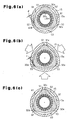
- the motor housing 15 has a cylindrical shape and the stator core 32 has a substantially triangle cross-sectional shape.
- First to third fastening interference portions 32c, 32d, 32e are each formed at an outer circumferential portion of the stator core 32.
- the outer circumferential surface of the motor housing 15 is pressed at three positions, radially inward from the outer side. This expands the portions of the motor housing 15 corresponding to the first to third fastening interference portions 32c to 32e in radial outward directions.
- a fitting interference ⁇ is defined between each of the first to third fastening surfaces S1 to S3 of the first to third fastening interference portions 32c to 32e and the inner circumferential surface 15a of the motor housing 15.
- the stator core 32 is inserted into the motor housing 15 and the motor housing 15 is released from the pressed state of Fig. 6(b).
- the motor housing 15 is deformed to restore the original cylindrical shape such that the motor housing 15 is pressed against the first to third fastening surfaces S1 to S3 of the first to third fastening interference portions 32c to 32e of the stator core 32.
- the stator core 32 is fastened to the motor housing 15 in accordance with a predetermined fastening interference ⁇ .
- the present invention may be further modified as follows.
- the motor housing 15 and the stator core 32 may be fastened together by different methods.
- the methods include, for example, mechanical deformation of either the motor housing 15 or the stator core 32 or both of the motor housing 15 and the stator core 32.
- the motor housing 15 may be deformed by a different method other than pressing.
- a plurality of tension tools may be employed at a plurality of positions of the outer circumferential surface of the motor housing 15. The tools thus apply tensile force to the motor housing 15, thus deforming the motor housing 15.
- pressing or tension tools may be employed at a plurality of positions of the inner circumferential surface of the stator core 32.
- the tools thus apply pressing or tensile force to the stator core 32, thus deforming the stator core 32.
- the mechanical elastic deformation of the motor housing or the stator core 32 may be combined with the shrink fitting or shrink cooling.
- the circumferential dimension of the inner circumferential surface 15a of the motor housing 15 may be larger than that of the outer circumferential surface 32b of the stator core 32 and the stator core 32 may be fastened to the motor housing 15 through deformation of the motor housing 15.
- the motor housing 15 may be formed of a metal material other than aluminum that has a thermal expansion coefficient different than that of the iron material forming the stator core 32.
- An increased number of expanded portions may be formed in the motor housing 15. However, for ensuring a predetermined fastening interference, it is preferred to deploy three to five expanded portions in the motor housing 15.
- An increased number of fastening interference portions 32c to 32e may be formed in the stator core 32. However, for ensuring a predetermined fastening interference, it is preferred to deploy three to five fastening interference portions in the stator core 32.
- the motor housing 15 may be formed with an oval or triangle or square cross-sectional shape.
Landscapes
- Engineering & Computer Science (AREA)
- Mechanical Engineering (AREA)
- General Engineering & Computer Science (AREA)
- Power Engineering (AREA)
- Combustion & Propulsion (AREA)
- Chemical & Material Sciences (AREA)
- Physics & Mathematics (AREA)
- Electromagnetism (AREA)
- Compressor (AREA)
- Iron Core Of Rotating Electric Machines (AREA)
- Rotary Pumps (AREA)
- Applications Or Details Of Rotary Compressors (AREA)
- Motor Or Generator Frames (AREA)
Claims (11)
- Procédé d'assemblage d'un compresseur (10) à moteur électrique du type hermétique entraîné par un moteur ayant un boîtier de moteur cylindrique (15) et un noyau de stator annulaire (32) fixé à l'intérieur du boîtier de moteur, le procédé étant caractérisé par :une déformation mécanique du boîtier de moteur, d'une manière élastique, afin de permettre au noyau de stator de s'insérer dans le boîtier de moteur ; etune restauration du boîtier de moteur déformé dans la forme originale, grâce à une force de restauration de forme élastique, le noyau de stator étant inséré dans le boîtier de moteur, de telle sorte que le boîtier de moteur fixe le noyau du stator.
- Procédé selon la revendication 1, caractérisé par :la définition d'une forme de circonférence interne du boîtier de moteur (15) et une forme de circonférence externe du noyau de stator (32), de telle sorte qu'une interférence d'attache prédéterminée (δ) soit définie entre le boîtier de moteur et le noyau de stator, lorsque le boîtier de moteur est séparé du noyau de stator ;la déformation élastique du boîtier de moteur en appliquant une force extérieure au boîtier de moteur, afin d'éliminer l'interférence d'attache ;l'insertion du noyau de stator dans le boîtier de moteur, le boîtier de moteur étant maintenu dans un état déformé sur le plan élastique ; etla libération de la force extérieure provenant du boîtier de moteur, le noyau de stator étant inséré dans le boîtier de moteur, afin de restaurer de manière élastique le boîtier de moteur dans l'état original, de telle sorte que le boîtier de moteur attache le noyau de stator.
- Procédé selon la revendication 2 caractérisé en ce que :le boîtier de moteur (15) et le noyau de stator (32) sont formés de telle sorte que le boîtier de moteur (15) présente des portions dilatées (15b, 15c, 15d ; 15h) qui s'étendent radialement vers l'extérieur et des portions d'interférence d'attache (15e, 15f, 15g ; 15i) qui s'étendent radialement vers l'intérieur, par rapport à la surface de circonférence externe du noyau de stator et en ce que la dimension de circonférence de la surface de circonférence interne du boîtier de moteur, au niveau des portions dilatées, est plus grande que la dimension de circonférence de la surface de circonférence externe du noyau de stator, les portions dilatées du boîtier de moteur étant déformées, de telle sorte que les portions d'interférence sont décalées radialement vers l'extérieur de la surface de circonférence externe du noyau de stator, afin de permettre que le noyau de stator soit inséré dans le boîtier de moteur.
- Procédé selon la revendication 2 ou 3, caractérisé en ce que l'interférence d'attache (δ) est supérieure à une interférence d'attache qui peut être définie dans un alésage par contraction ou le refroidissement par contraction du noyau de stator (32) et du boîtier de moteur (15).
- Procédé selon l'une quelconque des revendications 2 à 4, caractérisé par :la fourniture d'une pluralité de portions d'interférence d'attache (15e, 15f, 15g, 15i, 32c, 32d, 32e) dans la direction de la circonférence d'au moins l'un du boîtier de moteur (15) et du noyau de stator (32), l'interférence d'attache prédéterminée (δ) étant définie au niveau d'une portion située entre le boîtier de moteur et le noyau de stator qui correspond à chacune des portions d'interférence d'attache, lorsque le boîtier de moteur est séparé du noyau de stator ;la déformation sur le plan élastique du boîtier de moteur en appliquant une force de pression comme force externe sur une pluralité de portions de la surface de circonférence externe du boîtier de moteur, dans des directions radiales dirigées vers l'intérieur, de telle sorte que les portions du boîtier de moteur correspondant aux portions d'interférence d'attache sont déplacées dans la direction radiale vers l'extérieur du boîtier de moteur ;la libération de la force du boîtier de moteur, le noyau du stator étant inséré dans le boîtier du moteur, de telle sorte que les portions du boîtier de moteur correspondant aux portions d'interférence fixent le noyau de stator.
- Procédé selon la revendication 5, caractérisé en ce que les portions d'interférence d'attache (15e, 15f, 15g ; 15i) sont formées dans le boîtier de moteur (15), le boîtier de moteur incluant une pluralité de portions dilatées (15b, 15c, 15d ; 15h) dilatées radialement vers l'extérieur, chacune des portions dilatées étant agencée entre les portions adjacentes correspondantes des portions d'interférence d'attache dans la direction de la circonférence du boîtier de moteur, et dans lequel, lorsque les portions dilatées sont pressées dans des directions radiales dirigées vers l'intérieur du boîtier de moteur par un outil de pression (36, 37), le boîtier de moteur est déformé sur le plan élastique, de telle sorte que les portions d'interférence d'attache sont déplacées radialement vers l'extérieur.
- Procédé selon la revendication 6, caractérisé en ce que les portions dilatées (15e, 15f, 15g ; 15i) sont disposées en trois à cinq positions le long de la direction de la circonférence du boîtier de moteur.
- Procédé selon la revendication 5, caractérisé en ce que les portions d'interférence d'attache (32c, 32d, 32e) sont formées dans le noyau de stator (32), et dans lequel, lorsque les portions du boîtier de moteur (15) qui ne correspondent pas aux portions d'interférence d'attache sont pressées radialement vers l'intérieur, grâce à un outil de pression (36, 37), le boîtier de moteur est déformé de manière élastique, de telle sorte que les portions du boîtier de moteur correspondant aux portions d'interférence d'attache sont déplacées radialement vers l'extérieur.
- Procédé selon la revendication 8, caractérisé en ce que les portions d'interférence d'attache (32c, 32d, 32e) sont fournies en trois à cinq positions le long de la direction de la circonférence du noyau de stator (32).
- Procédé selon l'une quelconque des revendications 1 à 9, caractérisé en ce que le noyau de stator est composé de matériau du type fer, et dans lequel le boîtier de moteur est composé d'un métal ayant un coefficient de dilatation thermique différent de celui du matériau du type fer.
- Procédé selon la revendication 10, caractérisé en ce que le boîtier de moteur est composé en forgeant de l'aluminium.
Applications Claiming Priority (2)
| Application Number | Priority Date | Filing Date | Title |
|---|---|---|---|
| JP2003392357A JP4269907B2 (ja) | 2003-11-21 | 2003-11-21 | 密閉型電動圧縮機におけるステータコアの組み付け方法 |
| JP2003392357 | 2003-11-21 |
Publications (2)
| Publication Number | Publication Date |
|---|---|
| EP1533527A1 EP1533527A1 (fr) | 2005-05-25 |
| EP1533527B1 true EP1533527B1 (fr) | 2007-09-12 |
Family
ID=34431629
Family Applications (1)
| Application Number | Title | Priority Date | Filing Date |
|---|---|---|---|
| EP04027475A Expired - Lifetime EP1533527B1 (fr) | 2003-11-21 | 2004-11-19 | Méthode d'assemblage d'un boîtier de moteur et d'un stator de moteur d'un compresseur de type hermétique |
Country Status (6)
| Country | Link |
|---|---|
| US (1) | US7363696B2 (fr) |
| EP (1) | EP1533527B1 (fr) |
| JP (1) | JP4269907B2 (fr) |
| KR (1) | KR100572186B1 (fr) |
| CN (1) | CN1328842C (fr) |
| DE (1) | DE602004008860T2 (fr) |
Cited By (1)
| Publication number | Priority date | Publication date | Assignee | Title |
|---|---|---|---|---|
| KR102523872B1 (ko) | 2022-01-19 | 2023-04-20 | 엘지전자 주식회사 | 압축기 |
Families Citing this family (44)
| Publication number | Priority date | Publication date | Assignee | Title |
|---|---|---|---|---|
| JP4036148B2 (ja) * | 2002-07-23 | 2008-01-23 | 株式会社豊田自動織機 | 電動モータ及び電動コンプレッサ |
| JP4449811B2 (ja) * | 2005-04-15 | 2010-04-14 | 株式会社豊田自動織機 | 電動コンプレッサ |
| JP2007170227A (ja) * | 2005-12-20 | 2007-07-05 | Sanden Corp | 流体機械 |
| JP2007244150A (ja) * | 2006-03-10 | 2007-09-20 | Toyota Industries Corp | 電動モータ及び電動圧縮機 |
| JP4857910B2 (ja) * | 2006-05-24 | 2012-01-18 | 株式会社豊田自動織機 | 電動モータ及び電動圧縮機 |
| JPWO2008072513A1 (ja) * | 2006-12-07 | 2010-03-25 | サンデン株式会社 | 圧縮機 |
| JP4928978B2 (ja) * | 2007-02-23 | 2012-05-09 | 三菱重工業株式会社 | 電動圧縮機 |
| FR2915534B1 (fr) | 2007-04-25 | 2009-05-29 | Danfoss Commercial Compressors | Procede d'assemblage d'un compresseur frigorifique. |
| US7952253B2 (en) * | 2007-08-30 | 2011-05-31 | Woodward, Inc. | Stator laminations for rotary actuator |
| JP2009112096A (ja) * | 2007-10-29 | 2009-05-21 | Toyota Industries Corp | ステータコアの固定方法および電動圧縮機 |
| JP5217704B2 (ja) * | 2008-07-07 | 2013-06-19 | 株式会社デンソー | 回転電機の固定子の製造装置および固定子の製造方法 |
| FR2935560B1 (fr) * | 2008-09-03 | 2011-07-15 | Michelin Soc Tech | Stator pour machine electrique tournante et son procede de fabrication |
| CN102122868B (zh) * | 2010-01-08 | 2016-06-29 | 思博莫顿股份公司 | 电机定子及其制造方法 |
| JP5562753B2 (ja) * | 2010-07-29 | 2014-07-30 | 三洋電機株式会社 | 直流モータおよびハブユニット |
| US9267504B2 (en) | 2010-08-30 | 2016-02-23 | Hicor Technologies, Inc. | Compressor with liquid injection cooling |
| EP2612035A2 (fr) | 2010-08-30 | 2013-07-10 | Oscomp Systems Inc. | Compresseur à refroidissement par injection de liquide |
| JP5978456B2 (ja) * | 2011-09-26 | 2016-08-24 | パナソニックIpマネジメント株式会社 | 電動圧縮機 |
| US9964122B2 (en) | 2012-04-30 | 2018-05-08 | Emerson Climate Technologies, Inc. | Compressor staking arrangement and method |
| US9806566B2 (en) * | 2012-08-30 | 2017-10-31 | Asmo Co., Ltd. | Brushless motor, stator, stator manufacturing method and brushless motor manufacturing method |
| TWI472129B (zh) * | 2012-11-21 | 2015-02-01 | Ind Tech Res Inst | 定子結構 |
| DE102012223592A1 (de) * | 2012-12-18 | 2014-07-03 | Robert Bosch Gmbh | Geometrie zum Ausgleich axial auftretender Spalte in Elektropumpen |
| JP6064652B2 (ja) * | 2013-02-15 | 2017-01-25 | 三菱電機株式会社 | 電動機及び電動送風機、この電動送風機を備えた電気掃除機 |
| JP2015081572A (ja) | 2013-10-23 | 2015-04-27 | 株式会社デンソー | 燃料ポンプの製造方法 |
| JP6208534B2 (ja) * | 2013-10-25 | 2017-10-04 | 株式会社ヴァレオジャパン | 電動スクロール圧縮機 |
| JP2015208164A (ja) * | 2014-04-22 | 2015-11-19 | サンデンホールディングス株式会社 | 電動圧縮機 |
| JP6323146B2 (ja) * | 2014-04-26 | 2018-05-16 | 日本電産株式会社 | モータおよび送風機 |
| JP6357365B2 (ja) * | 2014-06-27 | 2018-07-11 | サンデンホールディングス株式会社 | 電動圧縮機 |
| CN106787309A (zh) * | 2015-11-19 | 2017-05-31 | 德昌电机(深圳)有限公司 | 单相永磁无刷电机 |
| CN106787271A (zh) * | 2015-11-19 | 2017-05-31 | 上海鸣志电器股份有限公司 | 一种过盈配合连接的电机铁芯与机壳装置 |
| JP6355268B2 (ja) * | 2016-03-08 | 2018-07-11 | 本田技研工業株式会社 | 嵌合構造及び被嵌合部材の製造方法 |
| DE102016125384A1 (de) * | 2016-12-22 | 2018-06-28 | OET GmbH | Scrollkompressor |
| CN106655545B (zh) * | 2017-01-18 | 2023-04-25 | 江西拓又达科技集团有限公司 | 一种盘式风力发电机有铁芯的定子及制作方法 |
| CN107013460B (zh) * | 2017-04-28 | 2020-06-30 | 上海海立新能源技术有限公司 | 一种压缩机 |
| DE102017220424B4 (de) | 2017-11-16 | 2021-01-14 | Vitesco Technologies GmbH | Werkzeug und Verfahren zur Anordnung eines Stators in ein Gehäuse |
| GB2579358B (en) * | 2018-11-28 | 2021-06-09 | Jaguar Land Rover Ltd | A stator and a stator housing for an electric machine |
| GB2579357B (en) * | 2018-11-28 | 2021-10-06 | Jaguar Land Rover Ltd | A stator and stator housing |
| JP7167849B2 (ja) * | 2019-05-21 | 2022-11-09 | 株式会社デンソー | ステータアセンブリ、及び、モータ |
| EP3920374B1 (fr) | 2019-07-02 | 2025-08-27 | Samsung Electronics Co., Ltd. | Moteur et compresseur le comprenant |
| EP4002648A4 (fr) | 2019-09-30 | 2023-08-16 | Daikin Industries, Ltd. | Machine électrique tournante, compresseur et procédé de fabrication de machine électrique tournante |
| ES3033089T3 (en) * | 2020-06-30 | 2025-07-30 | Daikin Ind Ltd | Compressor |
| CN113794290B (zh) * | 2021-09-13 | 2022-12-20 | 珠海格力节能环保制冷技术研究中心有限公司 | 电机、压缩机、空调器 |
| CN118043558A (zh) * | 2021-10-12 | 2024-05-14 | 三菱电机株式会社 | 涡旋压缩机及其制造方法 |
| WO2025074808A1 (fr) * | 2023-10-06 | 2025-04-10 | 株式会社Ihi | Machine hydraulique |
| FR3154560A1 (fr) * | 2023-10-18 | 2025-04-25 | Valeo Systèmes D’Essuyage | Ensemble pour moteur électrique à stator et carter de protection améliorés |
Family Cites Families (8)
| Publication number | Priority date | Publication date | Assignee | Title |
|---|---|---|---|---|
| JPH03151591A (ja) | 1989-11-07 | 1991-06-27 | Sanyo Electric Co Ltd | 回転式圧縮機 |
| JPH05268740A (ja) | 1992-03-17 | 1993-10-15 | Seiko Epson Corp | 冷凍サイクル用コンプレッサ |
| JP4230014B2 (ja) * | 1997-09-25 | 2009-02-25 | 株式会社デンソー | 電動圧縮機の取付構造 |
| JP2000224787A (ja) | 1999-01-27 | 2000-08-11 | Denso Corp | 密閉型電動圧縮機 |
| JP2001078385A (ja) | 1999-09-06 | 2001-03-23 | Tokyo Parts Ind Co Ltd | 予圧機構を有する玉軸受を備えた小型モータ |
| JP2001280249A (ja) * | 2000-03-31 | 2001-10-10 | Matsushita Electric Ind Co Ltd | 圧縮機および電動機 |
| JP2002221166A (ja) * | 2001-01-29 | 2002-08-09 | Mitsubishi Electric Corp | スクロール圧縮機 |
| JP2003269335A (ja) | 2002-03-13 | 2003-09-25 | Daikin Ind Ltd | 回転式圧縮機 |
-
2003
- 2003-11-21 JP JP2003392357A patent/JP4269907B2/ja not_active Expired - Fee Related
-
2004
- 2004-07-23 KR KR1020040057773A patent/KR100572186B1/ko not_active Expired - Fee Related
- 2004-11-19 DE DE602004008860T patent/DE602004008860T2/de not_active Expired - Lifetime
- 2004-11-19 EP EP04027475A patent/EP1533527B1/fr not_active Expired - Lifetime
- 2004-11-19 US US10/993,595 patent/US7363696B2/en not_active Expired - Fee Related
- 2004-11-19 CN CNB2004100952398A patent/CN1328842C/zh not_active Expired - Fee Related
Non-Patent Citations (1)
| Title |
|---|
| None * |
Cited By (1)
| Publication number | Priority date | Publication date | Assignee | Title |
|---|---|---|---|---|
| KR102523872B1 (ko) | 2022-01-19 | 2023-04-20 | 엘지전자 주식회사 | 압축기 |
Also Published As
| Publication number | Publication date |
|---|---|
| CN1619924A (zh) | 2005-05-25 |
| KR20050049321A (ko) | 2005-05-25 |
| JP2005155368A (ja) | 2005-06-16 |
| KR100572186B1 (ko) | 2006-04-18 |
| DE602004008860T2 (de) | 2008-06-12 |
| JP4269907B2 (ja) | 2009-05-27 |
| US7363696B2 (en) | 2008-04-29 |
| US20050115055A1 (en) | 2005-06-02 |
| EP1533527A1 (fr) | 2005-05-25 |
| CN1328842C (zh) | 2007-07-25 |
| DE602004008860D1 (de) | 2007-10-25 |
Similar Documents
| Publication | Publication Date | Title |
|---|---|---|
| EP1533527A1 (fr) | Méthode d'assemblage d'un boítier de moteur et d'un stator de moteur d'un compresseur de type hermétique | |
| EP1384893B1 (fr) | Moteur électrique et compresseur hermétique | |
| US7538468B2 (en) | Electric motor and electric compressor with improved housing and stator | |
| JP4928978B2 (ja) | 電動圧縮機 | |
| EP3920374B1 (fr) | Moteur et compresseur le comprenant | |
| US10393116B2 (en) | Scroll type fluid machine | |
| EP1712794B1 (fr) | Compresseur électrique | |
| US20170284396A1 (en) | Electric compressor | |
| JP2000213463A (ja) | 密閉型圧縮機及びその組立方法 | |
| JP2006183527A (ja) | 流体機械 | |
| EP0400951A1 (fr) | Dispositif d'étanchéité axiale pour compresseur à spirales | |
| KR102850958B1 (ko) | 모터 및 이를 포함하는 압축기 | |
| KR20200063728A (ko) | 전동 압축기 | |
| JPWO2016199884A1 (ja) | 電動圧縮機 | |
| JP4045125B2 (ja) | 電動圧縮機 | |
| WO2004081378A2 (fr) | Structure de support de cylindre et compresseur volumetrique a pistons | |
| KR20200031868A (ko) | 스크롤형 압축기 | |
| JP2021106455A (ja) | 電動圧縮機 | |
| CN223387540U (zh) | 用于涡旋压缩机的十字滑环组件和涡旋压缩机 | |
| KR20100006237A (ko) | 전동식 압축기 | |
| US7255318B2 (en) | Stud mounting system | |
| JP2026001142A5 (fr) | ||
| KR20260005611A (ko) | 로터 및 이를 포함하는 전동 압축기 | |
| JP2026001142A (ja) | 電動機、圧縮機、及び機器 | |
| WO2024176546A1 (fr) | Moteur électrique, compresseur et dispositif |
Legal Events
| Date | Code | Title | Description |
|---|---|---|---|
| PUAI | Public reference made under article 153(3) epc to a published international application that has entered the european phase |
Free format text: ORIGINAL CODE: 0009012 |
|
| 17P | Request for examination filed |
Effective date: 20041119 |
|
| AK | Designated contracting states |
Kind code of ref document: A1 Designated state(s): AT BE BG CH CY CZ DE DK EE ES FI FR GB GR HU IE IS IT LI LU MC NL PL PT RO SE SI SK TR |
|
| AX | Request for extension of the european patent |
Extension state: AL HR LT LV MK YU |
|
| AKX | Designation fees paid |
Designated state(s): DE FR IT |
|
| GRAP | Despatch of communication of intention to grant a patent |
Free format text: ORIGINAL CODE: EPIDOSNIGR1 |
|
| GRAS | Grant fee paid |
Free format text: ORIGINAL CODE: EPIDOSNIGR3 |
|
| GRAA | (expected) grant |
Free format text: ORIGINAL CODE: 0009210 |
|
| AK | Designated contracting states |
Kind code of ref document: B1 Designated state(s): DE FR IT |
|
| REF | Corresponds to: |
Ref document number: 602004008860 Country of ref document: DE Date of ref document: 20071025 Kind code of ref document: P |
|
| ET | Fr: translation filed | ||
| PLBE | No opposition filed within time limit |
Free format text: ORIGINAL CODE: 0009261 |
|
| STAA | Information on the status of an ep patent application or granted ep patent |
Free format text: STATUS: NO OPPOSITION FILED WITHIN TIME LIMIT |
|
| 26N | No opposition filed |
Effective date: 20080613 |
|
| REG | Reference to a national code |
Ref country code: FR Ref legal event code: PLFP Year of fee payment: 12 |
|
| PGFP | Annual fee paid to national office [announced via postgrant information from national office to epo] |
Ref country code: IT Payment date: 20151124 Year of fee payment: 12 |
|
| PGFP | Annual fee paid to national office [announced via postgrant information from national office to epo] |
Ref country code: FR Payment date: 20151008 Year of fee payment: 12 |
|
| REG | Reference to a national code |
Ref country code: FR Ref legal event code: ST Effective date: 20170731 |
|
| PG25 | Lapsed in a contracting state [announced via postgrant information from national office to epo] |
Ref country code: FR Free format text: LAPSE BECAUSE OF NON-PAYMENT OF DUE FEES Effective date: 20161130 Ref country code: IT Free format text: LAPSE BECAUSE OF NON-PAYMENT OF DUE FEES Effective date: 20161119 |
|
| PGFP | Annual fee paid to national office [announced via postgrant information from national office to epo] |
Ref country code: DE Payment date: 20191105 Year of fee payment: 16 |
|
| REG | Reference to a national code |
Ref country code: DE Ref legal event code: R119 Ref document number: 602004008860 Country of ref document: DE |
|
| PG25 | Lapsed in a contracting state [announced via postgrant information from national office to epo] |
Ref country code: DE Free format text: LAPSE BECAUSE OF NON-PAYMENT OF DUE FEES Effective date: 20210601 |