EP1385261A2 - Moteur électrique freiné - Google Patents
Moteur électrique freiné Download PDFInfo
- Publication number
- EP1385261A2 EP1385261A2 EP03016120A EP03016120A EP1385261A2 EP 1385261 A2 EP1385261 A2 EP 1385261A2 EP 03016120 A EP03016120 A EP 03016120A EP 03016120 A EP03016120 A EP 03016120A EP 1385261 A2 EP1385261 A2 EP 1385261A2
- Authority
- EP
- European Patent Office
- Prior art keywords
- electric motor
- braking
- valve
- armature
- field winding
- Prior art date
- Legal status (The legal status is an assumption and is not a legal conclusion. Google has not performed a legal analysis and makes no representation as to the accuracy of the status listed.)
- Withdrawn
Links
- 238000004804 winding Methods 0.000 claims abstract description 113
- 230000005284 excitation Effects 0.000 claims description 35
- 230000005669 field effect Effects 0.000 claims description 16
- 230000001276 controlling effect Effects 0.000 claims description 9
- 230000001105 regulatory effect Effects 0.000 claims description 3
- 239000004065 semiconductor Substances 0.000 claims description 3
- 238000000926 separation method Methods 0.000 claims description 2
- 230000000638 stimulation Effects 0.000 abstract 1
- 238000012986 modification Methods 0.000 description 16
- 230000004048 modification Effects 0.000 description 16
- 238000013461 design Methods 0.000 description 6
- 239000003990 capacitor Substances 0.000 description 5
- 238000000034 method Methods 0.000 description 4
- 238000011161 development Methods 0.000 description 3
- 230000005405 multipole Effects 0.000 description 3
- 238000010276 construction Methods 0.000 description 2
- 238000010586 diagram Methods 0.000 description 2
- 230000000977 initiatory effect Effects 0.000 description 2
- 230000000712 assembly Effects 0.000 description 1
- 238000000429 assembly Methods 0.000 description 1
- 230000015572 biosynthetic process Effects 0.000 description 1
- 238000005352 clarification Methods 0.000 description 1
- 238000007599 discharging Methods 0.000 description 1
- 230000000694 effects Effects 0.000 description 1
- 238000002955 isolation Methods 0.000 description 1
- 238000012423 maintenance Methods 0.000 description 1
Images




Classifications
-
- H—ELECTRICITY
- H02—GENERATION; CONVERSION OR DISTRIBUTION OF ELECTRIC POWER
- H02P—CONTROL OR REGULATION OF ELECTRIC MOTORS, ELECTRIC GENERATORS OR DYNAMO-ELECTRIC CONVERTERS; CONTROLLING TRANSFORMERS, REACTORS OR CHOKE COILS
- H02P3/00—Arrangements for stopping or slowing electric motors, generators, or dynamo-electric converters
- H02P3/06—Arrangements for stopping or slowing electric motors, generators, or dynamo-electric converters for stopping or slowing an individual dynamo-electric motor or dynamo-electric converter
Definitions
- the invention relates to a braked electric motor with at least a field winding and a commutating armature that with the at least one field winding and in Motor operation is fed from a supply voltage with Means for switching to braking.
- the invention further relates to an electric motor in the form of a Asynchronous motor with squirrel-cage rotor.
- a braked electric motor designed as a series motor the type mentioned at the outset is known from WO 91/03866.
- This is used to brake the series motor when switching from motor operation to braking operation a closed, circuit disconnected from the supply voltage via the Field windings, reversing pole windings and the armature formed.
- to Limitation of the braking current is a current path between the armature and a reversing pole winding formed by two in the opposite direction Zener diodes connected in parallel is regulated.
- Another series motor is known from DE 36 36 555 A1 become known in which a self-excited braking at Switching from motor operation to braking operation achieved shall be. To ensure that braking is initiated, a capacitor is provided, which in motor operation via a Diode is charged. When switching to braking mode the braking process is initiated by discharging the capacitor.
- This electric motor also has a special multi-pole Switch necessary, which must be designed so that initially the circuit reliably from the supply voltage is disconnected before the brake circuit via a field winding and the anchor is closed. Furthermore, the Use of a capacitor to initiate braking regarded as disadvantageous, since only a single capacitor discharge is possible to initiate the braking process. Enough this does not mean a reliable initiation of the braking process to ensure so once the capacitor is discharged braking is no longer possible afterwards.
- the invention is based on the object to create a braked electric motor, making it reliable Braking on the simplest and cheapest possible Way on the one hand with a series motor and on the other hand can be achieved with an asynchronous motor with squirrel-cage rotor can.
- This task takes shape with a braked electric motor a series motor according to the type mentioned above solved in that the means to switch to braking at least a bridging of the anchor and an external excitation a field winding by the supply voltage in the Allow braking.
- the known circuit is one Electric motor in front, with the armature and field winding (s) in series are switched.
- the circuit is via armature and Field winding (s) interrupted and at least one field winding externally excited via the supply voltage while the armature is short-circuited.
- the motor therefore becomes Brakes operated as a separately excited DC generator.
- the Task with an asynchronous motor with at least two, preferably three, field windings, preferably in star connection, and solved with a squirrel-cage rotor that means for Switching to braking mode are provided when switching in braking operation an at least two-pole separation allow the field windings from the supply voltage, whereby a controllable valve between at least two field windings is provided, which acts as a freewheel valve in braking operation and is open in engine operation, and at least one, preferably two field windings in braking mode via a valve are externally excited by the supply voltage, which in Engine operation is open.
- the asynchronous machine is in braking mode the short-circuit rotor braked.
- means to limit the voltage on the at least one field winding provided in braking mode can be a act so-called free-wheel valve.
- the series motor to bridge the armature in braking mode controllable valve provided, which is connected in parallel to the armature is.
- Also to influence the excitation current through the at least a controllable valve can be provided in a field winding.
- a controllable valve is intended entirely generally a switch, a relay, but especially a semiconductor with suitable control, such as a triac, a thyristor, a transistor, in particular a field effect transistor or the like can be understood more.
- this can be used to control a controllable valve on.
- Optocouplers e.g. an optodiode with a Opto-triac can be provided. This creates a decoupling between a control circuit and the circuit to be switched guaranteed, in which the controllable valve lies.
- a controllable valve e.g. the usage of a relay.
- specifying a current direction can be a Diode (valve) can be used.
- this connects controllable valve the at least one field winding in braking mode via a load resistor with the supply voltage.
- this connects controllable valve which has at least one field winding over a Load resistance and at least one field winding with the Supply voltage.
- the excitation results from the product of the number of turns and the current results in a corresponding number of turns result in greater excitement despite significantly lower current. Therefore may have a higher resistance value for the load resistance can be selected, whereby the resulting power loss is lower.
- a controllable valve is provided, which in Row connected with an excitation winding parallel to the armature is.
- a phase control be provided via which a switch, preferably in the form of a triac that is controlled in series with the minimum a field winding and the anchor.
- a transistor preferably a Field effect transistor, provided, preferably by one Pulse width modulation control (PWM) is controlled, and the with the at least one field winding and the anchor in series lies.
- PWM Pulse width modulation control
- Such a circuit can easily be used if the supply voltage is a DC voltage.
- the transistor in the motor circuit is preferably via a Rectifiers, especially a bridge rectifier, to the Supply voltage or to the at least one field winding or the armature winding connected.
- a valve provided that parallel to the at least one field winding is connected to the separately excited braking during braking is used.
- the control of the excitation current in braking mode by the minimum a field winding a transistor, preferably a Field-effect transistor used, preferably via a Pulse width modulation control is controlled.
- a pulse width modulation control can be used controlled transistor both for controlling the motor current in motor operation as well as for controlling the braking current be used in braking mode, which changes the circuit overall simplified.
- phase control is used to control the motor in motor operation to be used and to control the Motor in braking mode, i.e. to limit the excitation current, if a transistor is to be used, this is preferred via a valve to the anchor or the at least one Field winding connected.
- the PWM control used can be switched off, it is sufficient a diode as a valve. Otherwise it is preferred a valve that can be switched off is used.
- A is preferably used to control a controllable valve Optocouplers used with an optotriac.
- the control of the engine both in engine operation and in brake operation uses a leading edge control via which a switch is preferably controlled in the form of a triac in series with the at least one field winding and the anchor.
- the leading edge control only controls in braking mode a half-wave corresponding to the current direction required for braking on.
- the valve acting as a freewheel valve is preferably used operated in braking mode with a current flow angle of 180 ° becomes external excitation during the current flow angle of the valve can be controlled to a value of ⁇ 180 ° in braking mode.
- An electric motor according to the invention can, for example advantageous for operating a braked power tool use, such as to operate a braked angle grinder, a saw or the like.
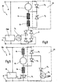
- a series motor 10 according to the invention in 2 shows the series motor 10 'in the Braking operation.
- the series motor 10 and 10 comprises two field windings 14, 16 and an armature 12, which is a commutating in the usual way Has armature coil connected via brushes which is only indicated schematically in FIGS. 1 and 2 are.
- the armature 12 is connected in series between the two field windings 14, 16 and can be connected to a supply voltage source 17 via a switch S 1 (motor switch).
- a power switch S 0 can be provided for switching the entire motor on and off, via which the connection to the supply voltage 17 takes place. So far, it is the known circuit of a series motor with a symmetrical arrangement of the armature 12 between two field windings 14, 16.
- the circuit is first separated via the two field windings 14, 16 and the armature 12 by opening the switch S 1 . Furthermore, the armature 12 is short-circuited via a switch S 2 parallel thereto, while the field winding 14 is connected via a switch S 3 to the other pole of the supply voltage, so that external excitation results. It goes without saying that the switches S 2 , S 3 are open during engine operation, as can be seen from the illustration in FIG. 1.
- FIG. 3 A generalized version of the series motor 10 or 10 'according to Figures 1 and 2 is shown in Fig. 3 and designated overall by the number 10a.
- the series motor 10a includes an armature 12 and two field windings 14, 16, which are in series with each other lie. While in Fig. 3 a symmetrical arrangement of the armature 12 is shown, so that the anchor 12 between the is arranged in principle, both field windings 14, 16 an asymmetrical arrangement is also conceivable, the two Field windings 14, 16 are directly connected to one another and at one end via the armature 12 with the supply voltage are coupled.
- the switches S 1 , S 2 , S 3 mentioned in FIGS. 1 and 2 are shown in generalized form in FIG. 3 as any assemblies which allow a current to be controlled. This can be a complete interruption, such as a mechanical switch or a relay, or a complete control or any intermediate values. A current limitation can possibly be achieved through a resistor or an inductance.
- Such a module can be completely realized with electronic means by a semiconductor with appropriate control, for example a triac, a thyristor, a transistor, in particular a field effect transistor, etc.
- the series motor 10a according to FIG. 3 has a further assembly S 4 , which is connected in parallel to a field winding 14 and which, depending on the execution of assembly S 3, is used for the field winding 14 limit the voltage.
- the module S 3 contains fast electronic switches, such as in pulse width modulation control, this could result in harmful voltage peaks which can be limited by the module S 4 .
- S 4 is therefore generally used to denote a freewheel valve for limiting voltage peaks, which in the simplest case could be a diode.
- S 3 can be opened to completely separate the circuit from the supply voltage. This applies to all variants of the invention.
- a series motor according to the invention can be used of a few electronic components particularly easy, Set up inexpensively and reliably, as shown below of examples according to Figures 4 to 15 is explained in more detail.
- the structure can be made so that the brake electronics is separated from the engine electronics in such a way that in the Retrofit a motor with a brake circuit is possible. There is practically only one signal line between Engine electronics and brake electronics necessary to complete the braking process to activate.
- the following circuits are for clarification the brake electronics as a brake module 20 with a dashed line highlighted separately.
- the motor 10b comprises an armature 12 which is connected in series symmetrically between two field windings 14, 16. While one field winding 14 is connected directly to a pole of the supply voltage 17 with its end facing away from the armature 12, the other field winding 16 is connected to the second pole at its end facing away from the armature 12 via a valve V 1 , which is designed as a triac the supply voltage 17 connected.
- the valve V 1 is controlled via a phase control 18 in a manner known per se. Up to this point, the connection of the series motor with field windings 14, 16, armature and triac V 1 with phase control 18 in motor operation corresponds to the prior art.
- a brake module designated overall by the number 20, which comprises two valves V 3 , V 4 and a load resistor R 1 .
- the valve V 3 is connected, which in the case shown is a thyristor, which can be controlled, for example, via an optocoupler (not shown).
- the valve V 3 enables the armature winding 12 to be bridged in the manner explained with reference to FIGS. 2 and 3.
- the valve V 4 is also connected, via which the field winding 14 is connected from one pole of the supply voltage 17 via a load resistor R 1 to the other pole of the supply voltage source 17.
- the excitation current flows in braking mode.
- This valve V 4 can also be a thyristor, for example, which is controlled, for example, by an optocoupler (not shown).
- valve V 1 When switching to braking operation, valve V 1 is first opened and valves V 3 , V 4 are switched on. The armature 12 and the valve V 3 are thus short-circuited and the field winding 14 is externally excited via the valve V 4 and the load resistor R 1 from the supply voltage source 17. Since both valves V 3 , V 4 are equally connected with their anodes between armature 12 and field winding 14, the reversal of the current direction in the armature is automatically predetermined when switching over to braking operation.
- valve V 4 is a switching element with a preferred direction, i.e. at least a mechanical switch or a relay, in series with a diode.
- valve V 4 is preferably designed as an electronic component with a preferred direction that can be switched, such as a thyristor.
- the load resistor R 1 serves to limit the excitation current and can be designed, for example, as a power resistor with approximately 150 watts, provided the series motor 10b is designed as a braked universal motor with a power of approximately 1000 watts.
- FIG. 5 A modification of the series motor according to FIG. 4 is shown in FIG Fig. 5 shown and generally designated by the number 10c.
- FIG. 6 A further modification of this embodiment is shown in FIG. 6 and is designated overall by the number 10d.
- the only difference from the embodiment according to FIG. 5 is that instead of an additional excitation winding L 1, an additional excitation winding L 2 is now provided, which is in series with the valve V 4 and the load resistor R 1 .
- FIG. 7 Another embodiment of a series motor according to the invention is shown in Fig. 7 and overall with the Number 10e.
- the circuit in question is designed for operation with direct current, which results in a simplified execution.
- the two field coils 14, 16 asymmetrical to the armature 12 arranged, which in principle also in the previously described Designs and other designs described below is always possible.
- a valve V 1 is provided, which is designed as a field effect transistor, which is connected with source and drain to the negative pole of the supply voltage 17 or to the armature 12.
- the field effect transistor is controlled via a pulse width modulation control PWM at its gate.
- a controllable valve V 3 is connected in parallel to the armature 12, which can be designed, for example, as a thyristor, which is connected with its cathode to the drain of the field effect transistor V 1 .
- a valve V 2 is connected between the drain of the valve V 1 and the positive pole of the supply voltage 17, which serves as a freewheel valve.
- the valve V 2 is simply designed as a diode, which is connected with its cathode to the positive pole and with its anode to the cathode of the valve V 3 or the armature 12 or drain of the valve V 1 .
- valve V 2 avoids the build-up of overvoltages that could occur over the distance formed from the armature 12 and the two field windings 14, 16.
- valve V 3 is turned off and power is controlled by valve V 1 .
- valve V 1 is first switched off and then valve V 3 is switched on with a time delay. Then valve V 1 is switched on for the duration of the braking phase, for example 3 seconds, until the engine stops. Then V 1 and V 3 are switched off. The braking phase is now complete.
- FIG. 8 shows a modification of the circuit according to FIG. 7 for operation with alternating current and is designated overall by the number 10f.
- the armature 12 is arranged asymmetrically to the two field windings 14, 16 and is connected to the supply voltage 17 with one pole.
- the two field windings 14, 16 connected in series with the armature 12 are connected at their other end to a bridge rectifier 21, whose other AC input is connected to the other pole of the supply voltage source 17.
- the valve V 1 again in the form of a field effect transistor, is driven at its gate via the pulse width modulation control PWM and is connected to the positive pole and to the negative pole of the bridge rectifier 21 with a drain.
- valve V 3 To bridge the armature 12, the valve V 3 is connected in parallel, while the valve V 2 , which in turn serves as a free-wheeling valve, is connected in parallel to the two field windings 14, 16.
- the valves V 2 , V 3 which in turn can be designed, for example, as thyristors, are poled in such a way that their two cathodes are connected to one another.
- valves V 2 , V 3 are inactive during engine operation, so that the brake module 20 has no influence.
- the motor 10f is controlled exclusively via V 1 during motor operation, which is controlled via the pulse width modulation control PWM.
- valve V 1 is first switched off.
- the valves V 2 , V 3 are then switched on with a time delay and V 1 is switched on for the duration of the braking phase of, for example, about 3 seconds, until the engine stops.
- V 1 , V 2 and V are switched off, which ends the braking phase.
- FIG. 9 A further modification of the motor according to the invention is shown in Fig. 9 shown and generally designated by the number 10g.
- a controllable valve V 5 in the form of a field effect transistor is now used instead of a load resistor, which is controlled at its gate via a pulse width modulation control PWM.
- a symmetrical arrangement of the armature 12 between the two field windings 14, 16 is again shown. While one field winding 14 is connected to one pole of the supply voltage source 17, the other field winding 16 is connected at its end facing away from the armature 12 to the other pole of the supply voltage source 17 via a valve V 1 in the form of a triac. The triac is controlled via a phase control 18.
- a controllable valve V 3 is again provided to bridge the armature winding 12 during braking operation, while a controllable free-wheel valve V 2 is connected in parallel with the field winding 14 in order to limit voltage peaks at the field winding 14.
- the valve V 5 in the form of the field effect transistor, which is connected via a valve V 4 to the field winding 14 or the armature 12 and the two valves V 2 , V 3 , is used to control the excitation current in braking operation. If the pulse width modulation control PWM can be switched off, the valve V 4 only ensures the correct polarity at the valve V 5 . In the simplest case, it can be a diode.
- valve V 4 is a controllable valve, as are the two valves V 2 , V 3 , for example a thyristor.
- an optocoupler can in turn be used to control the valves V 2 , V 3 and possibly V 4 .
- valves V 2 , V 3 , V 4 are all connected with their anode side between field winding 14 and armature 12.
- valves V 2 , V 3 , V 4 , V 5 are switched off, so that the known circuit of a series-wound motor results, which is controlled via a triac V 1 with phase control 18.
- V 1 is first switched off via the phase control 18 and the valves V 2 , V 3 switched on with a certain time delay.
- the valves V 4 , V 5 are then switched on for the duration of the braking phase until the engine has come to a standstill.
- the valves V 4 , V 5 and V 2 , V 3 are then switched off, which ends the braking phase.
- FIG. 10 shows a modification of the series motor according to FIG. 9 with an asymmetrical arrangement of the armature 12 and is designated overall by 10 hours.
- the armature 12 is connected to one pole of the supply voltage source 17 and connected to the two field windings 14, 16 connected in series with another pole.
- the end of the field winding 16 facing away from the armature 12 is connected to the other pole of the supply voltage source 17 via the valve V 1 in the form of the triac.
- a phase control 18 is again used for the control.
- a controllable valve V 3 is connected in parallel, for example in the form of a thyristor.
- the freewheel valve V 2 is connected with its cathode to the cathode of the valve V 3 and the armature 12 or the field winding 14.
- the valve V 5 is again provided in the form of a field effect transistor, which is controlled via a pulse width modulation control PWM and via a valve V 4 between the triac and Field winding 16 is connected.
- V 4 can be a simple diode if the pulse width modulation control PWM can be switched off.
- FIG. 11 shows a possible form of implementation of the motor according to FIG Fig. 9 shown in greater detail and overall with 10i designated.
- the basic circuit of the motor 10i completely corresponds to the circuit of the motor 10g according to FIG. 9. Only the valves V 2 , V 3 and V 4 , which were only indicated by way of example in the circuit according to FIG. 9, are now shown in their concrete configuration.
- V 4 is designed as a simple diode, since V 5 can be switched off via the pulse width modulation control PWM.
- the two valves V 2 , V 3 are each designed as a triac, which are controlled via an optotriac.
- the valve V 2 (freewheel) has a triac 22 which is connected between the armature 12 and the field winding 14 via a diode 24 which is connected to the supply voltage source 17 with its cathode.
- the triac 22 is controlled by an optotriac 28, which is connected on the one hand to the gate of the triac 22 and on the other hand is connected via a resistor 26 to the connection to the anode of the diode 24.
- the optotriac 28 is connected via a resistor 30 to the line 40, which is connected to the anode of the valve V 4 , the armature 12 and the field winding 14.
- the Optotriac 28 is controlled by an LED.
- the valve V 3 has a triac 32 for bridging the armature 12, which is connected in parallel to the armature 12 between the line 40 and the connection to the field winding 16. There is no need for a diode in this circuit.
- the triac 32 is in turn controlled via an optotriac 38, which is connected to the gate of the triac 32, is coupled to the line 40 via a resistor 36 and is connected via a resistor 34 to the connection of the triac 32 to the armature 12 and field winding 16 ,
- An LED is used to control the Optotriacs.
- the triacs 22, 32 could also be used immediately Optotriacs be trained, provided components with sufficient Performance are readily available. In the present Case, however, the triacs 22, 32 are designed as power triac, while the Optotriacs 28, 38 only as controls are performed with low power.
- the mode of operation of the motor 10i according to FIG. 11 corresponds completely the functioning of the motor 10g according to FIG. 9.
- FIG. 12 A modification of the embodiment according to FIG. 8 is shown in FIG. 12 shown and designated overall by 10j.
- the pulse width modulation control according to FIG. 8 was replaced by a phase control 18. This controls the valve V 1 , which is now in the form of a triac, both in engine operation and in braking operation.
- the rectifier 21 is naturally omitted here. Otherwise the mode of operation of this circuit corresponds completely to the mode of operation previously explained with reference to FIG. 8.
- the Triac V1 is typically used with both Controlled half-waves.
- the phase gating angle is ⁇ between 90 ° and 180 °.
- the embodiment according to FIG. 12 has less compared to FIG. 8 Component, is space-saving and has lower losses.
- FIG. 13 is a modification of the design of the engine according to Fig. 10 shown and designated overall by 10k.
- the circuit was simplified compared to the embodiment according to FIG. 10 in that a valve V 6 in the form of a triad was inserted into the connecting line between the armature 12 or field winding 14 and the diodes V 2 , V 3 , which is controlled via the control 42 of the Valve V 5 (PWM) is controlled.
- the valves V 2 , V 3 can be designed as simple diodes in this case. Otherwise, the mode of operation of the circuit corresponds completely to that according to FIG. 10.
- control 42 for the PWM shown separately in FIGS. 13 and 14 can be combined with the control 18 for V 1 and can be designed as a microcontroller, for example.
- FIG. 15 shows an embodiment of an electric motor according to the invention in the form of an asynchronous motor and is designated overall by 10 m.
- the motor 10m is designed as a 3-phase motor with three field windings 14, 15, 16, which are arranged in a star connection and are fed by the phases L 1 , L 2 and L 3 of the supply voltage with a frequency of 300 Hz, for example.
- the armature is designed as a short-circuit rotor and is not shown here.
- Such a motor is also used as a power tool called an HF machine (not to be confused with high frequency in the sense of electromagnetic waves in the MHz range or higher).
- HF machines are used for power tools used in particularly heavy loads in continuous operation, as they are maintenance free due to the lack of brushes are.
- a two-pole on / off switch S 1 with the two poles 50 and 52 is used to switch the motor 10m on and off and to switch between motor operation and braking operation.
- the braking circuit designated 20 in total serves to brake the motor 10m.
- the brake circuit 20 has a valve V 8 , which is connected in series with a diode 48 and via which the two field windings 14, 16 are connected in series between the phases L 1 and L 3 when the valve V 8 is closed, and thus from the network with a pulsating DC voltage.
- a valve V 7 acting as a freewheel valve is closed via a line 54 and is in series with a diode 46.
- the free running valve V 7 prevents the motor from continuing to run 10 m in braking mode.
- the two valves V 7 , V 8 can be designed, for example, as triacs, which are controlled by a control 44.
- valves V 7 , V 8 are open and switch S 1 is closed, so that the known circuit of a 3-phase asynchronous motor is in star connection.
- switch S 1 is opened and valves V 7 , V 8 are closed. While the valve V 7 is fully opened, that is to say is operated with a flow angle of 180 °, the flow angle of the valve V 8 can preferably be regulated to a desired value between 0 ° and 180 ° by means of the controller 44 in order to control the braking enable.
- valves V 7 , V 8 can optionally also be designed as any other controllable valves, for example as transistors, in particular as field-effect transistors.
Landscapes
- Engineering & Computer Science (AREA)
- Power Engineering (AREA)
- Stopping Of Electric Motors (AREA)
- Electric Propulsion And Braking For Vehicles (AREA)
Applications Claiming Priority (2)
| Application Number | Priority Date | Filing Date | Title |
|---|---|---|---|
| DE10234397 | 2002-07-23 | ||
| DE10234397A DE10234397A1 (de) | 2002-07-23 | 2002-07-23 | Gebremster Reihenschlussmotor und Verfahren zum Bremsen eines Reihenschlussmotors |
Publications (2)
| Publication Number | Publication Date |
|---|---|
| EP1385261A2 true EP1385261A2 (fr) | 2004-01-28 |
| EP1385261A3 EP1385261A3 (fr) | 2005-08-17 |
Family
ID=29796610
Family Applications (1)
| Application Number | Title | Priority Date | Filing Date |
|---|---|---|---|
| EP03016120A Withdrawn EP1385261A3 (fr) | 2002-07-23 | 2003-07-16 | Moteur électrique freiné |
Country Status (3)
| Country | Link |
|---|---|
| US (1) | US6998804B2 (fr) |
| EP (1) | EP1385261A3 (fr) |
| DE (1) | DE10234397A1 (fr) |
Cited By (10)
| Publication number | Priority date | Publication date | Assignee | Title |
|---|---|---|---|---|
| WO2005099081A1 (fr) * | 2004-04-08 | 2005-10-20 | Robert Bosch Gmbh | Ensemble circuit et procede pour freiner par court-circuit un moteur a courant continu |
| US7023159B2 (en) | 2002-10-18 | 2006-04-04 | Black & Decker Inc. | Method and device for braking a motor |
| US7075257B2 (en) | 2002-10-18 | 2006-07-11 | Black & Decker Inc. | Method and device for braking a motor |
| WO2008138600A3 (fr) * | 2007-05-14 | 2009-04-23 | Repower Systems Ag | Dispositif de réglage de pales de rotor d'une éolienne |
| WO2010105903A3 (fr) * | 2009-03-03 | 2011-02-03 | Robert Bosch Gmbh | Dispositif de freinage électrodynamique pour un moteur universel |
| WO2011076827A3 (fr) * | 2009-12-23 | 2012-08-16 | Robert Bosch Gmbh | Dispositif de freinage pour moteur universel |
| WO2013095721A3 (fr) * | 2011-12-19 | 2013-08-15 | Progress Rail Services Corporation | Frein dynamique à variation continue pour une locomotive |
| EP2947765A3 (fr) * | 2014-05-20 | 2016-06-01 | Black & Decker Inc. | Freinage électronique destiné à un moteur universel dans un outil électrique |
| EP2741413A3 (fr) * | 2012-12-08 | 2018-01-17 | Festool GmbH | Machine-outil manuelle dotée d'un dispositif de freinage électrique |
| US11047528B2 (en) | 2016-02-12 | 2021-06-29 | Black & Decker Inc. | Electronic braking for a power tool having a brushless motor |
Families Citing this family (7)
| Publication number | Priority date | Publication date | Assignee | Title |
|---|---|---|---|---|
| US7075040B2 (en) * | 2003-08-21 | 2006-07-11 | Barnstead/Thermolyne Corporation | Stirring hot plate |
| DE102004038829A1 (de) * | 2004-08-04 | 2006-03-16 | C. & E. Fein Gmbh | Schrauber |
| WO2007118336A1 (fr) * | 2006-04-19 | 2007-10-25 | Railpower Technologies Corp. | Circuit de freinage dynamique pour locomotive hybride |
| KR20100064741A (ko) * | 2008-12-05 | 2010-06-15 | 삼성전자주식회사 | 직류모터 제어장치 및 그 방법 |
| RU2550395C1 (ru) * | 2014-03-20 | 2015-05-10 | Открытое акционерное общество Научно-исследовательский и конструкторско-технологический институт подвижного состава (ОАО "ВНИКТИ") | Тяговый электропривод транспортного средства |
| WO2017115594A1 (fr) * | 2015-12-28 | 2017-07-06 | 日立工機株式会社 | Outil électrique |
| TWI730281B (zh) | 2018-01-03 | 2021-06-11 | 美商米沃奇電子工具公司 | 電動工具中之電子制動技術 |
Citations (4)
| Publication number | Priority date | Publication date | Assignee | Title |
|---|---|---|---|---|
| DE3636555A1 (de) | 1986-10-28 | 1988-05-11 | Schroecker Rainer | Schaltungsanordnung zum bremsen eines kollektormotors |
| WO1991003866A1 (fr) | 1989-09-06 | 1991-03-21 | Hans Hermann Rottmerhusen | Moteur a collecteur |
| EP0578366A2 (fr) | 1992-06-05 | 1994-01-12 | Black & Decker Inc. | Dispositif de freinage contrôlé pour moteurs électriques et en particulier pour outils portatifs |
| US5828194A (en) | 1996-03-01 | 1998-10-27 | Magnetek S.P.A. | Control circuit for control of a direct-current motor normally excited in series including structure for separate excitation during braking |
Family Cites Families (20)
| Publication number | Priority date | Publication date | Assignee | Title |
|---|---|---|---|---|
| US3340449A (en) * | 1965-01-29 | 1967-09-05 | Gen Motors Corp | Induction motor braking system |
| DE2348880C3 (de) * | 1973-09-28 | 1981-04-23 | Siemens AG, 1000 Berlin und 8000 München | Waschautomatenantrieb |
| US3872363A (en) * | 1974-03-11 | 1975-03-18 | Thomas A O Gross | Electric motor braking system |
| GB1585261A (en) * | 1976-02-19 | 1981-02-25 | Ass Elect Ind | Dynamic braking of direct current motors |
| DE2810201C2 (de) * | 1978-03-09 | 1985-11-14 | Robert Bosch Gmbh, 7000 Stuttgart | Verfahren und Vorrichtung zur Energieversorgung von an das Bordnetz eines Kraftfahrzeugs angeschlossenen elektrischen Verbrauchern |
| US4311948A (en) * | 1979-04-02 | 1982-01-19 | National Research Development Corporation | Dynamic braking of A.C. motors |
| US4250436A (en) * | 1979-09-24 | 1981-02-10 | The Singer Company | Motor braking arrangement and method |
| IN152808B (fr) * | 1980-06-02 | 1984-04-14 | Siemens Ag | |
| JPS6020870A (ja) * | 1983-07-12 | 1985-02-02 | 日立工機株式会社 | クラツチ式電動締付工具の制御方式 |
| US5041771A (en) * | 1984-07-26 | 1991-08-20 | Pt Components, Inc. | Motor starting circuit |
| EP0197436B1 (fr) * | 1985-04-01 | 1992-07-29 | BSG-Schalttechnik GmbH & Co. KG | Dispositif d'un commutateur |
| DE3802419A1 (de) * | 1988-01-28 | 1989-08-10 | Bosch Gmbh Robert | Bremsschaltung fuer universalmotoren |
| US4857818A (en) * | 1988-05-03 | 1989-08-15 | Hobbs Taz D | Electric motor brake |
| WO1991000386A1 (fr) | 1989-06-30 | 1991-01-10 | Nekoosa Papers, Inc. | Procede de blanchiment de pate a papier kraft avec un melange d'oxygene et de peroxyde |
| DE4216838A1 (de) * | 1992-05-21 | 1993-12-16 | Danijel Golub | Abtriebsfreie mechanische Bremse |
| DE4333294A1 (de) * | 1993-09-30 | 1995-04-06 | Bosch Gmbh Robert | Elektromotor mit elektrodynamischer Bremse |
| US6188203B1 (en) * | 1996-11-01 | 2001-02-13 | Lucas Aerospace Power Equipment Corporation | Ground fault detection circuit |
| DE19651298C2 (de) * | 1996-12-10 | 1999-04-01 | Fein C & E | Reihenschlußmotor mit Kommutator und Bremswicklung |
| US6236177B1 (en) * | 1998-06-05 | 2001-05-22 | Milwaukee Electric Tool Corporation | Braking and control circuit for electric power tools |
| ATE284089T1 (de) * | 2000-05-08 | 2004-12-15 | Gianpietro Bianchi | Elektronische vorrichtung zur steuerung des elektromagnetischen selbstbremsstromes in reversiblen rotierenden elektrischen kommutatormaschinen |
-
2002
- 2002-07-23 DE DE10234397A patent/DE10234397A1/de not_active Withdrawn
-
2003
- 2003-07-16 EP EP03016120A patent/EP1385261A3/fr not_active Withdrawn
- 2003-07-23 US US10/625,176 patent/US6998804B2/en not_active Expired - Fee Related
Patent Citations (4)
| Publication number | Priority date | Publication date | Assignee | Title |
|---|---|---|---|---|
| DE3636555A1 (de) | 1986-10-28 | 1988-05-11 | Schroecker Rainer | Schaltungsanordnung zum bremsen eines kollektormotors |
| WO1991003866A1 (fr) | 1989-09-06 | 1991-03-21 | Hans Hermann Rottmerhusen | Moteur a collecteur |
| EP0578366A2 (fr) | 1992-06-05 | 1994-01-12 | Black & Decker Inc. | Dispositif de freinage contrôlé pour moteurs électriques et en particulier pour outils portatifs |
| US5828194A (en) | 1996-03-01 | 1998-10-27 | Magnetek S.P.A. | Control circuit for control of a direct-current motor normally excited in series including structure for separate excitation during braking |
Cited By (20)
| Publication number | Priority date | Publication date | Assignee | Title |
|---|---|---|---|---|
| US7023159B2 (en) | 2002-10-18 | 2006-04-04 | Black & Decker Inc. | Method and device for braking a motor |
| US7075257B2 (en) | 2002-10-18 | 2006-07-11 | Black & Decker Inc. | Method and device for braking a motor |
| WO2005099081A1 (fr) * | 2004-04-08 | 2005-10-20 | Robert Bosch Gmbh | Ensemble circuit et procede pour freiner par court-circuit un moteur a courant continu |
| WO2008138600A3 (fr) * | 2007-05-14 | 2009-04-23 | Repower Systems Ag | Dispositif de réglage de pales de rotor d'une éolienne |
| US8344532B2 (en) | 2007-05-14 | 2013-01-01 | Repower Systems Ag | Rotor blade adjustment device for a wind turbine |
| EP2559893A1 (fr) * | 2007-05-14 | 2013-02-20 | REpower Systems AG | Dispositif de réglage de pales de rotor d'une éolienne |
| CN101802394B (zh) * | 2007-05-14 | 2013-05-01 | 再生动力系统股份公司 | 用于风能设备的风轮叶片调节装置 |
| RU2528413C2 (ru) * | 2009-03-03 | 2014-09-20 | Роберт Бош Гмбх | Электродинамическое тормозное устройство для универсального двигателя |
| WO2010105903A3 (fr) * | 2009-03-03 | 2011-02-03 | Robert Bosch Gmbh | Dispositif de freinage électrodynamique pour un moteur universel |
| WO2011076827A3 (fr) * | 2009-12-23 | 2012-08-16 | Robert Bosch Gmbh | Dispositif de freinage pour moteur universel |
| US9590538B2 (en) | 2009-12-23 | 2017-03-07 | Robert Bosch Gmbh | Braking device for a universal motor |
| CN103998280A (zh) * | 2011-12-19 | 2014-08-20 | 铁路发展服务公司 | 用于机车的连续可变动态制动器 |
| US8820248B2 (en) | 2011-12-19 | 2014-09-02 | Progress Rail Services Corp | Continuously variable dynamic brake for a locomotive |
| US9071178B2 (en) | 2011-12-19 | 2015-06-30 | Progress Rail Services Corp. | Continuously variable dynamic brake for a locomotive |
| CN103998280B (zh) * | 2011-12-19 | 2016-05-04 | 铁路发展服务公司 | 用于机车的连续可变动态制动器 |
| WO2013095721A3 (fr) * | 2011-12-19 | 2013-08-15 | Progress Rail Services Corporation | Frein dynamique à variation continue pour une locomotive |
| EP2741413A3 (fr) * | 2012-12-08 | 2018-01-17 | Festool GmbH | Machine-outil manuelle dotée d'un dispositif de freinage électrique |
| EP2947765A3 (fr) * | 2014-05-20 | 2016-06-01 | Black & Decker Inc. | Freinage électronique destiné à un moteur universel dans un outil électrique |
| US9614466B2 (en) | 2014-05-20 | 2017-04-04 | Black & Decker Inc. | Electronic braking for a universal motor in a power tool |
| US11047528B2 (en) | 2016-02-12 | 2021-06-29 | Black & Decker Inc. | Electronic braking for a power tool having a brushless motor |
Also Published As
| Publication number | Publication date |
|---|---|
| DE10234397A1 (de) | 2004-01-29 |
| EP1385261A3 (fr) | 2005-08-17 |
| US6998804B2 (en) | 2006-02-14 |
| US20040130282A1 (en) | 2004-07-08 |
Similar Documents
| Publication | Publication Date | Title |
|---|---|---|
| EP1385261A2 (fr) | Moteur électrique freiné | |
| EP0721693B1 (fr) | Circuit de freinage pour moteur universel | |
| DE102005002327A1 (de) | Elektronisch kommutierter Elektromotor und Verfahren zur Steuerung eines solchen | |
| DE112004002917B4 (de) | Schaltungsanordnung zum Ansteuern eines Schaltschützes und deren Verwendung bei einem Zwischenkreisumrichter | |
| DE1806465A1 (de) | Wechselrichteranordnung | |
| EP2659582A2 (fr) | Procédé et dispositif pour faire fonctionner un moteur électrique à excitation séparée ou hybride | |
| DE4201005C2 (de) | Schaltungsanordnung zum netzunabhängigen, aussetzerfreien Bremsen eines Reihenschlußmotors | |
| DE2829685C2 (de) | Mit Gleichspannung gespeister Motor | |
| DE10146523A1 (de) | Antriebssteuereinrichtung für einen stromrichtergespeisten, mehrphasigen Motor | |
| EP2104221A1 (fr) | Procédé de commande d'un moteur électrique multiphasé monté en étoile | |
| DE19912121A1 (de) | Reihenschlußmotor | |
| DE102009034310A1 (de) | Schaltnetzteil | |
| CH660652A5 (de) | Wechselrichter-anordnung. | |
| DE2113040A1 (de) | System und elektronische Vorrichtung zur elektrischen Bremsung von Induktionsmotoren | |
| DE2146064A1 (de) | Anordnung zur vermeidung des ratterns und riefens von schleifringbuersten fuer gleichstrom, die zeitweise ohne betriebsstrom betrieben werden | |
| DE102008049536B3 (de) | Kreisstromunterdrückende Ansteuerung bei einer Gleichrichterschaltung | |
| DE2839712B2 (de) | Schaltung mit Zerhackerfunktion für einen bürstenlosen Gleichstrommotor | |
| DE102012012601A1 (de) | Verfahren und Vorrichtung zum Anlauf einer bürstenlosen Gleichstrommaschine mit mehreren Strängen für ein Fahrzeug | |
| DE3049020C2 (de) | Regelbarer Gleichspannungswandler für Leistungsschaltnetzteile | |
| EP2319976B1 (fr) | Appareil ménager destiné à l'entretien de pièces de linge et procédé de fonctionnement d'un moteur à courant continu à brosses | |
| DE2116043B2 (de) | Anordnung zur selbsttätigen kon tinuierlichen Feldschwachung eines über einen elektronischen Gleichstromsteller gespeisten Gleichstrom Reihenschluß motors | |
| DE10250449A1 (de) | Kommutierungsverfahren, insbesondere für einen kollektorlosen Gleichstrommotor | |
| DE4437488A1 (de) | Geschalteter Reluktanzmotor, insbesondere als Antriebsmotor im Kleinspannungsbereich bis 60 V | |
| DE102021208826A1 (de) | Elektrische Maschine mit einem Stator, einem insbesondere permanentmagnetisch ausgebildeten Rotor und einem Wechselrichter mit mehreren Phasen zum Antrieb der elektrischen Maschine sowie ein Lenkungssystem mit solch einer elektrischen Maschine | |
| EP2510609B1 (fr) | Procédé pour faire fonctionner une machine à courant continu sans balais et machine à courant continu |
Legal Events
| Date | Code | Title | Description |
|---|---|---|---|
| PUAI | Public reference made under article 153(3) epc to a published international application that has entered the european phase |
Free format text: ORIGINAL CODE: 0009012 |
|
| AK | Designated contracting states |
Kind code of ref document: A2 Designated state(s): AT BE BG CH CY CZ DE DK EE ES FI FR GB GR HU IE IT LI LU MC NL PT RO SE SI SK TR |
|
| AX | Request for extension of the european patent |
Extension state: AL LT LV MK |
|
| RAP1 | Party data changed (applicant data changed or rights of an application transferred) |
Owner name: C. & E. FEIN GMBH |
|
| RAP1 | Party data changed (applicant data changed or rights of an application transferred) |
Owner name: C. & E. FEIN GMBH |
|
| RIC1 | Information provided on ipc code assigned before grant |
Ipc: 7H 02P 3/12 B Ipc: 7H 02P 3/06 A |
|
| PUAL | Search report despatched |
Free format text: ORIGINAL CODE: 0009013 |
|
| AK | Designated contracting states |
Kind code of ref document: A3 Designated state(s): AT BE BG CH CY CZ DE DK EE ES FI FR GB GR HU IE IT LI LU MC NL PT RO SE SI SK TR |
|
| AX | Request for extension of the european patent |
Extension state: AL LT LV MK |
|
| RIC1 | Information provided on ipc code assigned before grant |
Ipc: 7H 02P 3/24 B Ipc: 7H 02P 3/22 B Ipc: 7H 02P 3/06 A Ipc: 7H 02P 3/12 B |
|
| 17P | Request for examination filed |
Effective date: 20060119 |
|
| AKX | Designation fees paid |
Designated state(s): AT BE BG CH CY CZ DE DK EE ES FI FR GB GR HU IE IT LI LU MC NL PT RO SE SI SK TR |
|
| RAP3 | Party data changed (applicant data changed or rights of an application transferred) |
Owner name: C. & E. FEIN GMBH |
|
| STAA | Information on the status of an ep patent application or granted ep patent |
Free format text: STATUS: THE APPLICATION IS DEEMED TO BE WITHDRAWN |
|
| 18D | Application deemed to be withdrawn |
Effective date: 20170201 |