EP2104221A1 - Procédé de commande d'un moteur électrique multiphasé monté en étoile - Google Patents
Procédé de commande d'un moteur électrique multiphasé monté en étoile Download PDFInfo
- Publication number
- EP2104221A1 EP2104221A1 EP08005423A EP08005423A EP2104221A1 EP 2104221 A1 EP2104221 A1 EP 2104221A1 EP 08005423 A EP08005423 A EP 08005423A EP 08005423 A EP08005423 A EP 08005423A EP 2104221 A1 EP2104221 A1 EP 2104221A1
- Authority
- EP
- European Patent Office
- Prior art keywords
- winding
- motor
- phase
- bridged
- engine
- Prior art date
- Legal status (The legal status is an assumption and is not a legal conclusion. Google has not performed a legal analysis and makes no representation as to the accuracy of the status listed.)
- Withdrawn
Links
- 238000000034 method Methods 0.000 title claims description 34
- 238000004804 winding Methods 0.000 claims description 93
- 238000005457 optimization Methods 0.000 claims description 6
- 238000000926 separation method Methods 0.000 abstract description 2
- 230000001360 synchronised effect Effects 0.000 description 10
- 239000004020 conductor Substances 0.000 description 7
- 238000011144 upstream manufacturing Methods 0.000 description 7
- 238000010586 diagram Methods 0.000 description 6
- 239000007858 starting material Substances 0.000 description 2
- 230000003213 activating effect Effects 0.000 description 1
- 230000002411 adverse Effects 0.000 description 1
- 238000011109 contamination Methods 0.000 description 1
- 230000005288 electromagnetic effect Effects 0.000 description 1
- 238000005516 engineering process Methods 0.000 description 1
- 230000007935 neutral effect Effects 0.000 description 1
Images

Classifications
-
- H—ELECTRICITY
- H02—GENERATION; CONVERSION OR DISTRIBUTION OF ELECTRIC POWER
- H02P—CONTROL OR REGULATION OF ELECTRIC MOTORS, ELECTRIC GENERATORS OR DYNAMO-ELECTRIC CONVERTERS; CONTROLLING TRANSFORMERS, REACTORS OR CHOKE COILS
- H02P25/00—Arrangements or methods for the control of AC motors characterised by the kind of AC motor or by structural details
- H02P25/16—Arrangements or methods for the control of AC motors characterised by the kind of AC motor or by structural details characterised by the circuit arrangement or by the kind of wiring
- H02P25/18—Arrangements or methods for the control of AC motors characterised by the kind of AC motor or by structural details characterised by the circuit arrangement or by the kind of wiring with arrangements for switching the windings, e.g. with mechanical switches or relays
-
- H—ELECTRICITY
- H02—GENERATION; CONVERSION OR DISTRIBUTION OF ELECTRIC POWER
- H02K—DYNAMO-ELECTRIC MACHINES
- H02K3/00—Details of windings
- H02K3/04—Windings characterised by the conductor shape, form or construction, e.g. with bar conductors
- H02K3/28—Layout of windings or of connections between windings
-
- H—ELECTRICITY
- H02—GENERATION; CONVERSION OR DISTRIBUTION OF ELECTRIC POWER
- H02P—CONTROL OR REGULATION OF ELECTRIC MOTORS, ELECTRIC GENERATORS OR DYNAMO-ELECTRIC CONVERTERS; CONTROLLING TRANSFORMERS, REACTORS OR CHOKE COILS
- H02P1/00—Arrangements for starting electric motors or dynamo-electric converters
- H02P1/16—Arrangements for starting electric motors or dynamo-electric converters for starting dynamo-electric motors or dynamo-electric converters
- H02P1/26—Arrangements for starting electric motors or dynamo-electric converters for starting dynamo-electric motors or dynamo-electric converters for starting an individual polyphase induction motor
- H02P1/38—Arrangements for starting electric motors or dynamo-electric converters for starting dynamo-electric motors or dynamo-electric converters for starting an individual polyphase induction motor by pole-changing
-
- H—ELECTRICITY
- H02—GENERATION; CONVERSION OR DISTRIBUTION OF ELECTRIC POWER
- H02P—CONTROL OR REGULATION OF ELECTRIC MOTORS, ELECTRIC GENERATORS OR DYNAMO-ELECTRIC CONVERTERS; CONTROLLING TRANSFORMERS, REACTORS OR CHOKE COILS
- H02P25/00—Arrangements or methods for the control of AC motors characterised by the kind of AC motor or by structural details
- H02P25/16—Arrangements or methods for the control of AC motors characterised by the kind of AC motor or by structural details characterised by the circuit arrangement or by the kind of wiring
- H02P25/18—Arrangements or methods for the control of AC motors characterised by the kind of AC motor or by structural details characterised by the circuit arrangement or by the kind of wiring with arrangements for switching the windings, e.g. with mechanical switches or relays
- H02P25/20—Arrangements or methods for the control of AC motors characterised by the kind of AC motor or by structural details characterised by the circuit arrangement or by the kind of wiring with arrangements for switching the windings, e.g. with mechanical switches or relays for pole-changing
Definitions
- the invention relates to a method for driving a multiphase star-motor electric motor and such an electric motor for carrying out the aforementioned method.
- Such triacs which are assigned to the individual motor windings as switches, have the advantage that, although they can be produced inexpensively, they have the disadvantage that conventional actuation involves self-holding switches, ie. H. which after switching on only lock again when the current flowing through the switch becomes 0 (zero) or changes its direction.
- soft starters are known in which a brushless three-phase electric motor is started by triacs. Such soft starters are used in conjunction with three-phase motors, on whose windings the mains voltage is applied, which can be lowered by phase control.
- phase control as such is not sufficient to achieve a start with a high torque or briefly increased torque of the motor.
- a method for controlling the ignition angle of a single-phase ac-powered electric motor is known, which ensures an increased torque when starting the engine and quiet running when the engine is started up and working by triacs, which energize main and auxiliary wind accordingly.
- This method works with a low-cost electronic control and cost-effective triacs and also allows to control the speed of the motor in quite wide ranges, and at a high efficiency.
- the invention has for its object to provide a method for driving a multi-phase star-connected electric motor, with a high starting torque or an increased torque can be achieved during engine operation, which is inexpensive and efficient to implement.
- a corresponding electric motor is to be provided for carrying out this method.
- the method according to the invention for driving a multiphase star-motor-driven electric motor provides for conducting over at least one winding part of one phase of the motor and for electrically disconnecting the bridged winding part from the rest of the motor.
- the inventive method is particularly advantageous for AC-powered, brushless permanent magnet motors, so typically used for electronically commutated polyphase DC motors but also for asynchronous motors.
- the basic idea of the method according to the invention is to supply by conductive bridging at least one winding part or a winding of one phase of the motor of the other or the remaining phases of the engine, a higher voltage and thus a higher current and thus greater electrical power, the motor then in a converts increased torque.
- a two-phase electric motor operated in a star connection only one winding part of one phase of the motor can be conductively bypassed and electrically isolated from the rest of the motor, whereas in triple- and multiphase electric motors operated in star connection, a complete winding of one phase can also be bypassed and switched off. Shutdown of the winding member is required to ensure that no braking action is produced in the bridged winding member or in the bridged winding by self-induction.
- the achievable with the method according to the invention increased torque for starting under load or in other operating situations can be used, in which this is needed.
- the inventive method when used in conjunction with an electronically commutated polyphase DC motor, the inventive method is advantageously used in the speed range, which is between 80 and 100% of the synchronous speed.
- Such motors in particular when used for driving centrifugal pumps, require an increased torque in order, for example, to reach the synchronous rotational speed during startup from a rotational speed which corresponds to 80% of the synchronous rotational speed.
- the motor windings are dimensioned correspondingly large, but this often leads to the fact that the motor is over-dimensioned during operation at synchronous speed and throttled by means of a phase control, which is basically not desirable.
- the engine can usually be dimensioned so that on the one hand reaches its synchronous speed comparatively quickly, on the other hand does not have to be throttled or only minimally throttled in operation with synchronous speed.
- the bridging and separation is canceled after starting the motor, in a brushless DC motor, so typically when reaching the synchronous speed or possibly also a lower or super-synchronous speed, if this is so control technology provided.
- a conductive bridging of winding parts are provided in all phases, in order to realize in this way in all remaining winding parts a higher current flow and thus a higher torque of the motor.
- winding parts of one, several or advantageously all phases can be conductively bridged.
- advantageously one entire winding is conductively bridged. It is understood that each of the bridged or the bridged winding parts are electrically isolated.
- the inventive method is advantageously carried out with electronic switches in the form of triacs, as they are available at low cost and intended for small and medium-sized services.
- each winding and the at least one electrically conductive bridging means of an electronic switch in particular one Triacs switched on and off, wherein after switching off the bridging the windings associated electronic switches for speed control or energy optimization of the engine are controlled.
- an electronic switch for carrying out the method according to the invention, as explained above, at least one electronic switch is required for activating the electrically conductive bridging.
- another electronic switch is to be connected in series with this winding.
- Particularly advantageous method of the invention for a brushless three-phase DC motor is used, which drives a centrifugal pump or is designed and designed for such a drive.
- the associated increased starting torque has not only advantages in terms of earlier reaching the synchronous or target speed, but also the advantage that, which is not completely ruled out in pumps, a tight-fitting impeller, as for example can occur due to contamination, can be better driven freely again, as an increased torque is available.
- the electric motor according to the invention for carrying out the above-described method is formed at least two-phase and has windings which are connected in a star connection.
- each winding can be switched on or off by means of an electronic switch, wherein at least one further electronic switch is provided, with which a bridging of at least part of a winding can be activated or deactivated.
- the electric motor has an electronic control unit, which controls the inventive method accordingly, d. H. the electronic switches, in particular triacs switches accordingly.
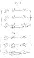
- Fig. 1 simplified electric motor has three windings W 1 , W 2 and W 3 , which are connected in a star connection, that are connected to one another electrically conductive at one end.
- the windings are connected via electronic switches in the form of triacs T 1 , T 2 and T 3 to the corresponding terminals L 1 , L 2 and L 3 of a three-phase supply network.
- the winding W 3 is formed divided and has a subsequent to the switch T 3 winding part W 3a and a subsequent to the neutral point S winding part W 3b . Between these winding parts W 3a and W 3b , the winding is contacted via a conductor L, which is connected via a triac T 4 to the terminal L 3 of the supply network.
- the switch T 4 For driving the motor with increased torque, the switch T 4 is closed, so that the winding part W 3a of the winding W 3 is conductively bypassed, that is ineffective with respect to the power supply of the motor.
- the switch T 3 In order to prevent a current from being induced in the winding part W 3a when the motor is running and an electromagnetic effect adversely affecting the running, the switch T 3 is simultaneously opened when the switch T 4 closes.
- the voltage applied to the terminal L 3 voltage is thus applied to the partial winding W 3b , which reduces the resistance of the effective winding W 3 to W 3b and thus a higher current through the windings W 1 and W 2 can flow, the increased moment compared to the operation with the windings W 1 , W 2 and W 3 allows.
- Each of the windings W 1 , W 2 and W 3 of the three-phase motor is formed divided, wherein the winding parts W 1a , W 2a and W 3a by means of the switches T 6 , T 5 and T 4 are each bridged and by means of the windings upstream switches T 1 , T 2 and T 3 are electrically separated from the bridged winding parts W 1a , W 2a and W 3a .
- All three windings W 1b , W 2b and W 3b then have a lower resistance, whereby in all three windings a higher current flows, which causes an increased torque of the motor.
- the three windings W 1 , W 2 and W 3 are not formed split, but it is the winding W 3 by means of the conductor L completely bridged.
- a triac T 4 is provided in the conductor L, which switches this parallel to the winding W 3 with the switch closed.
- a switch T 3 which is connected upstream of the winding W 3 , is then used to disconnect the winding W 3 from the power supply L 3 when it is bridged by the conductor L.
- the winding W 3 must be controlled as a two-phase motor, since the winding W 3 is ineffective.
- the motor runs at an increased torque compared to the normal operation, in which the switch T 4 is opened and the windings W 1 , W 2 and W 3 depending on the constructive Structure and mode of operation of the motor to the power terminals L 1 , L 2 and L 3 are connected.
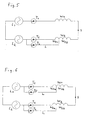
- the motor has the windings W 1 and W 2 , which are connected on one side at point S and abut separately with their other side on the supply network with the phases L 1 and L 2 via switches T 1 and T 2 .
- the winding W 2 is divided into two winding parts W 2a and W 2b , wherein in the region of the division, a conductor L is led out, the winding part W 2a via a switch T 4 conductively bridges, so that the supply voltage of the terminal L 2 directly on the winding part W 2b is pending.
- the winding W 2 upstream switch T 2 is opened as described above, that no current is induced during starting of the motor in the remaining ineffective connected winding part W 2a to ensure.
- FIG. 6 Based on Fig. 6 an alternative wiring of a two-phase motor is shown in which both windings W 1 and W 2 are designed split and each of these partial windings W 1a and W 2a by means of a conductor L by closing a switch T 5 and T 4 can be bridged conductive.
- the winding W 1 and W 2 upstream switches T 1 and T 2 is then opened.
- the voltage applied to the phase terminals L 1 and L 2 voltage is then applied directly to the partial windings W 1b and W 2b , whereby they are subjected to a higher voltage and thus the motor generates a higher torque.
- the above-described circuit variants can be used for a brushless electronically commutated DC motor or an asynchronous motor.
- the switches T 1 , T 2 and T 3 are used for starting and advantageous for energy optimization, but they can also be used for speed control.
- the switches T 1 to T 3 advantageously used for speed control and / or energy optimization.
- the switches T 3 and T 4 in the embodiment according to Fig. 2 the switches T 2 to T 5 , in the embodiment according to Fig. 3 the switches T 1 to T 6 and in the embodiment according to Fig. 4 the switches T 3 and T 4 .
Landscapes
- Engineering & Computer Science (AREA)
- Power Engineering (AREA)
- Control Of Motors That Do Not Use Commutators (AREA)
Priority Applications (4)
| Application Number | Priority Date | Filing Date | Title |
|---|---|---|---|
| EP08005423A EP2104221A1 (fr) | 2008-03-22 | 2008-03-22 | Procédé de commande d'un moteur électrique multiphasé monté en étoile |
| PCT/EP2009/002087 WO2009118135A1 (fr) | 2008-03-22 | 2009-03-20 | Procédé pour commander un moteur électrique polyphasé à montage en étoile |
| US12/933,459 US8796970B2 (en) | 2008-03-22 | 2009-03-20 | Method for controlling a multiphase electric motor operating in star-connected mode |
| CN200980110494.6A CN101981802B (zh) | 2008-03-22 | 2009-03-20 | 以星形连接方式运行的多相电动机的控制方法 |
Applications Claiming Priority (1)
| Application Number | Priority Date | Filing Date | Title |
|---|---|---|---|
| EP08005423A EP2104221A1 (fr) | 2008-03-22 | 2008-03-22 | Procédé de commande d'un moteur électrique multiphasé monté en étoile |
Publications (1)
| Publication Number | Publication Date |
|---|---|
| EP2104221A1 true EP2104221A1 (fr) | 2009-09-23 |
Family
ID=39710992
Family Applications (1)
| Application Number | Title | Priority Date | Filing Date |
|---|---|---|---|
| EP08005423A Withdrawn EP2104221A1 (fr) | 2008-03-22 | 2008-03-22 | Procédé de commande d'un moteur électrique multiphasé monté en étoile |
Country Status (4)
| Country | Link |
|---|---|
| US (1) | US8796970B2 (fr) |
| EP (1) | EP2104221A1 (fr) |
| CN (1) | CN101981802B (fr) |
| WO (1) | WO2009118135A1 (fr) |
Cited By (1)
| Publication number | Priority date | Publication date | Assignee | Title |
|---|---|---|---|---|
| EP2426815A3 (fr) * | 2010-09-03 | 2012-10-03 | C. & E. Fein GmbH | Entraînement électrique |
Families Citing this family (5)
| Publication number | Priority date | Publication date | Assignee | Title |
|---|---|---|---|---|
| US10320313B2 (en) * | 2015-03-10 | 2019-06-11 | Young Jun Kim | Arc free phase control alternatives for AC motor starters |
| JP6715046B2 (ja) * | 2016-03-22 | 2020-07-01 | Ntn株式会社 | 交流発電機のブレーキ装置 |
| DE102017130869A1 (de) | 2017-12-21 | 2019-06-27 | Hans-Peter Wyremba | Elektrisches Getriebe und Verfahren zum Betreiben eines Elektromotors |
| KR102880899B1 (ko) * | 2019-11-15 | 2025-11-04 | 현대자동차주식회사 | 모터 구동 제어 방법 및 시스템 |
| KR102524042B1 (ko) * | 2022-11-07 | 2023-04-21 | (주)루슨트코리아 | 속도변경 및 그에 따른 효율구간 변경이 가능한 전동기 또는 발전기 |
Citations (7)
| Publication number | Priority date | Publication date | Assignee | Title |
|---|---|---|---|---|
| FR1599481A (fr) * | 1968-02-14 | 1970-07-15 | ||
| DE19635597C1 (de) * | 1996-09-02 | 1998-01-15 | Apag Elektronik Ag Duebendorf | Elektrische Schaltungsanordnung zum Sanftanlauf und Sanftauslauf von Geräten, insbesondere Drehstrommotoren |
| WO2001050589A1 (fr) * | 1999-12-30 | 2001-07-12 | Varidigm Corporation | Appareil destine a des applications mettant en oeuvre un moteur electrique a vitesse variable en continu |
| GB2375665A (en) * | 2001-02-08 | 2002-11-20 | Scroll Tech | Compressor motor having two sets of windings |
| EP1443635A1 (fr) | 2003-01-21 | 2004-08-04 | Grundfos A/S | Procédé de contrôle d'un angle de déclenchement |
| EP1496606A1 (fr) * | 2003-07-09 | 2005-01-12 | C.E.SET. S.r.l. | Moteur électrique à induction |
| EP1775823A2 (fr) * | 2005-10-12 | 2007-04-18 | Moteurs Patay | Machine électrique |
Family Cites Families (10)
| Publication number | Priority date | Publication date | Assignee | Title |
|---|---|---|---|---|
| DE3046406A1 (de) * | 1980-12-10 | 1982-07-22 | IWE Ingenieurgesellschaft für wirtschaftliche Energienutzung mbH, 6078 Neu-Isenburg | Verfahren und schaltungsanordnung zum regeln bzw. steuern der drehzahl eines mit drehstrom betriebenen motors |
| US4482853A (en) * | 1981-08-24 | 1984-11-13 | Reuland Electric Company | Composite control for soft start and dynamic braking of a three-phase induction motor |
| DE3517570A1 (de) * | 1985-05-15 | 1986-11-20 | Deutsche Thomson-Brandt Gmbh, 7730 Villingen-Schwenningen | Schaltung zur steuerung eines buerstenlosen elektromotors |
| US4910450A (en) * | 1989-07-14 | 1990-03-20 | Louis W. Parker | Low cost three phase energy economizer |
| EP0489970A1 (fr) * | 1990-12-14 | 1992-06-17 | BSG-Schalttechnik GmbH & Co. KG | Procédé et appareil pour l'opération des entraînements électriques |
| US5637976A (en) * | 1995-09-29 | 1997-06-10 | Allen-Bradley Company, Inc. | Method and apparatus for RMS current measurement in induction motors without a current transformer |
| IT1288738B1 (it) * | 1996-10-08 | 1998-09-24 | Varian Spa | Unita' elettronica di comando per pompa da vuoto. |
| FR2779637B1 (fr) * | 1998-06-15 | 2000-09-01 | Oreal | Compositions cosmetiques photoprotectrices, contenant un nanopigment d'oxyde metallique et un terpolymere acrylique et utilisation de ces compositions pour proteger les matieres keratiniques contre le rayonnement ultraviolet |
| FR2891959B1 (fr) * | 2005-10-12 | 2008-07-04 | Moteurs Patay Soc Par Actions | Machine electrique polyphasee comportant un systeme de commutation pour commuter les elements de bobinage suivant differentes configurations |
| US8076890B2 (en) * | 2006-03-31 | 2011-12-13 | Thk Co., Ltd. | AC motor driving apparatus and control method |
-
2008
- 2008-03-22 EP EP08005423A patent/EP2104221A1/fr not_active Withdrawn
-
2009
- 2009-03-20 US US12/933,459 patent/US8796970B2/en active Active
- 2009-03-20 WO PCT/EP2009/002087 patent/WO2009118135A1/fr not_active Ceased
- 2009-03-20 CN CN200980110494.6A patent/CN101981802B/zh not_active Expired - Fee Related
Patent Citations (7)
| Publication number | Priority date | Publication date | Assignee | Title |
|---|---|---|---|---|
| FR1599481A (fr) * | 1968-02-14 | 1970-07-15 | ||
| DE19635597C1 (de) * | 1996-09-02 | 1998-01-15 | Apag Elektronik Ag Duebendorf | Elektrische Schaltungsanordnung zum Sanftanlauf und Sanftauslauf von Geräten, insbesondere Drehstrommotoren |
| WO2001050589A1 (fr) * | 1999-12-30 | 2001-07-12 | Varidigm Corporation | Appareil destine a des applications mettant en oeuvre un moteur electrique a vitesse variable en continu |
| GB2375665A (en) * | 2001-02-08 | 2002-11-20 | Scroll Tech | Compressor motor having two sets of windings |
| EP1443635A1 (fr) | 2003-01-21 | 2004-08-04 | Grundfos A/S | Procédé de contrôle d'un angle de déclenchement |
| EP1496606A1 (fr) * | 2003-07-09 | 2005-01-12 | C.E.SET. S.r.l. | Moteur électrique à induction |
| EP1775823A2 (fr) * | 2005-10-12 | 2007-04-18 | Moteurs Patay | Machine électrique |
Cited By (2)
| Publication number | Priority date | Publication date | Assignee | Title |
|---|---|---|---|---|
| EP2426815A3 (fr) * | 2010-09-03 | 2012-10-03 | C. & E. Fein GmbH | Entraînement électrique |
| US8493017B2 (en) | 2010-09-03 | 2013-07-23 | C. & E. Fein Gmbh | Electrical drive with switchable coil sections |
Also Published As
| Publication number | Publication date |
|---|---|
| CN101981802B (zh) | 2013-04-24 |
| WO2009118135A1 (fr) | 2009-10-01 |
| US8796970B2 (en) | 2014-08-05 |
| CN101981802A (zh) | 2011-02-23 |
| US20110012545A1 (en) | 2011-01-20 |
Similar Documents
| Publication | Publication Date | Title |
|---|---|---|
| EP0989666B9 (fr) | Système de commande de vitesse de moteurs AC | |
| EP2162046B1 (fr) | Dispositif d'entraînement électrique pour un appareil ménager à circulation d'eau | |
| DE102007040560A1 (de) | Verfahren zur Ansteuerung eines Umrichters sowie zugehörige Vorrichtung | |
| EP2104221A1 (fr) | Procédé de commande d'un moteur électrique multiphasé monté en étoile | |
| EP4372977A1 (fr) | Système d'entraînement | |
| EP2761732A2 (fr) | Moteur électrique notamment moteur à commutation de polarités, procédé pour faire fonctionner un moteur électrique et moteur électrique | |
| DE102014116689B4 (de) | Vorrichtung und Verfahren zum Sichern einer Antriebssteuerung gegen Versorgungsspannungsausfälle | |
| WO2013023806A2 (fr) | Procédé et dispositif de commande de machines triphasées | |
| DE102010062060A1 (de) | Drehstrom-Asynchronmaschine und Verfahren zum Betreiben einer Drehstrom-Asynchronmaschine in einem Luft- oder Raumfahrzeug | |
| EP3285381A1 (fr) | Procédé de fonctionnement d'une machine électrique et machine électrique | |
| EP0045951B1 (fr) | Procédé pour mettre en marche un convertisseur ayant un circuit intermédiaire à courant continu alimentant un moteur électrique synchrone | |
| DE602005004418T2 (de) | Ansteuerschaltung für einen elektrischen synchronmotor | |
| WO2012107127A1 (fr) | Dispositif d'accumulation d'énergie destiné à un moteur électrique à excitation séparée | |
| DE102012208631A1 (de) | Verfahren und Vorrichtung zum Betrieb eines bürstenlosen Motors | |
| DE102005045401A1 (de) | Verfahren zur Stromversorgung eines über eine Halbleiter-Leistungsendstufe elektronisch kommutierbaren Gleichstrommotors | |
| DE19815896C2 (de) | Drehzahl-Steuervorrichtung für einen elektronisch kommutierten mehrphasigen Elektromotor | |
| BE1030973B1 (de) | Antriebssystem | |
| EP1297615A1 (fr) | Procede pour faire fonctionner un moteur a courant continu sans balais | |
| EP0599334B2 (fr) | Procédé d'entraínement d'un moteur à reluctance | |
| EP1533892B1 (fr) | Méthode pour réduire le temps de freinage d'un moteur | |
| DE102017130869A1 (de) | Elektrisches Getriebe und Verfahren zum Betreiben eines Elektromotors | |
| WO2012107128A2 (fr) | Procédé de fonctionnement d'un système de commande pour une machine électrique et système de commande d'une machine électrique | |
| EP3361618B1 (fr) | Topologie à cinq commutateurs | |
| EP0618670B1 (fr) | Génératrice à courant alternatif | |
| EP1467477B1 (fr) | Méthode pour générer un couple élevé dans un moteur à induction polyphasé |
Legal Events
| Date | Code | Title | Description |
|---|---|---|---|
| PUAI | Public reference made under article 153(3) epc to a published international application that has entered the european phase |
Free format text: ORIGINAL CODE: 0009012 |
|
| AK | Designated contracting states |
Kind code of ref document: A1 Designated state(s): AT BE BG CH CY CZ DE DK EE ES FI FR GB GR HR HU IE IS IT LI LT LU LV MC MT NL NO PL PT RO SE SI SK TR |
|
| AX | Request for extension of the european patent |
Extension state: AL BA MK RS |
|
| 17P | Request for examination filed |
Effective date: 20100121 |
|
| 17Q | First examination report despatched |
Effective date: 20100215 |
|
| AKX | Designation fees paid |
Designated state(s): AT BE BG CH CY CZ DE DK EE ES FI FR GB GR HR HU IE IS IT LI LT LU LV MC MT NL NO PL PT RO SE SI SK TR |
|
| STAA | Information on the status of an ep patent application or granted ep patent |
Free format text: STATUS: THE APPLICATION HAS BEEN WITHDRAWN |
|
| 18W | Application withdrawn |
Effective date: 20181023 |