EP1386876B1 - Barrière de securité pour ascenseur - Google Patents
Barrière de securité pour ascenseur Download PDFInfo
- Publication number
- EP1386876B1 EP1386876B1 EP01919968.6A EP01919968A EP1386876B1 EP 1386876 B1 EP1386876 B1 EP 1386876B1 EP 01919968 A EP01919968 A EP 01919968A EP 1386876 B1 EP1386876 B1 EP 1386876B1
- Authority
- EP
- European Patent Office
- Prior art keywords
- cage
- members
- safety fence
- handrail
- elevator
- Prior art date
- Legal status (The legal status is an assumption and is not a legal conclusion. Google has not performed a legal analysis and makes no representation as to the accuracy of the status listed.)
- Expired - Lifetime
Links
Images


Classifications
-
- B—PERFORMING OPERATIONS; TRANSPORTING
- B66—HOISTING; LIFTING; HAULING
- B66B—ELEVATORS; ESCALATORS OR MOVING WALKWAYS
- B66B5/00—Applications of checking, fault-correcting, or safety devices in elevators
- B66B5/0043—Devices enhancing safety during maintenance
- B66B5/005—Safety of maintenance personnel
- B66B5/0081—Safety of maintenance personnel by preventing falling by means of safety fences or handrails, being operable or not, mounted on top of the elevator car
Definitions
- the present invention relates to an elevator cage, and more particularly, to an elevator cage on which is provided a safety fence for protecting a service technician at the time of maintenance and inspection of an elevator system.
- EP-A-0 985 628 discloses in combination the technical features of the pre-characterizing part of claims 1 and 2 below.
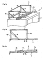
- a safety fence provided on a cage top 1a of an elevator cage 1 primarily comprises support members 3; front and rear pillar members 4a, 4b; handrail members 5; and arm members 6.
- each front pillar member 4a is pivotally joined to the center of the respective support member 3 by means of a pin.
- An end of each rear pillar member 4b is pivotally joined to one end of the respective support member 3 by means of a pin.
- One end of the handrail member 5 is pivotally joined to the remaining end of the respective front pillar member 4a by means of a pin.
- the other end of the handrail member 5 is pivotally joined to the remaining end of the respective rear pillar member 4b by means of a pin, in order to join the two pillar members 4b together.
- one end of each arm member 6 is pivotally joined to the center of the respective rear pillar member 4b means of a pin.
- the other end of each arm member 6 is pivotally joined, by means of a pin, to a position on the respective support member 3 closer to the rear pillar member 4b with reference to the center of the support member 3.
- each arm member 6 is primarily constituted of two plate members joined together by means of a pin, and a stopper provided in a position close to the pin for limiting pivotal movement of the two plate members.
- a service technician first gets on the cage top 1a from the side of the elevator cage 1 on which a door 2 is provided.
- the safety fence is then raised, and pivotal movement of the two plate members of each arm member 6 is limited by means of the respective stopper, whereupon pivotal movement of the other members is also limited.
- the service technician can perform a desired operation while being protected by the safety fence and from a fall.
- Fig. 5c is a side view showing a normal state of the known elevator cage.
- the safety fence is collapsed for ensuring space above the elevator cage 1 during a normal operation other than the maintenance and inspection operation. More specifically, the stopper of each arm member 6 is disengaged, thereby rendering the two plates pivotable about the pin. As a result, the respective members also become pivotable about their corresponding pins, and the safety fence is collapsed.
- the invention aims at solving such a situation of the known elevator cage and at providing an elevator cage which enables a service technician to raise a safety fence without fail at the time of maintenance and inspection, to thereby prevent falling of the service technician from the elevator cage without fail.
- the present invention relates to an elevator cage having a fixing member removably attached to a safety fence to be assembled on a cage top, wherein the fixing member is fixed to a position close to a doorway when the safety fence is folded down.
- the invention also relates to an elevator cage having a safety fence to be assembled on a cage top of an elevator cage, the safety fence having pillar members and handrail members, wherein the handrail members are pivotally joined to the pillar members such that a doorway is interrupted when the handrail members are folded down.
- the service technician raises the handrail members for getting on the cage top at the time of maintenance and inspection, to thereby assemble the safety fence.
- the invention also relates to an elevator cage based on the previous improved elevator cage, wherein stoppers are provided on the respective pillar members for limiting a rotation angle of the handrail members.
- stoppers are provided on the respective pillar members for limiting a rotation angle of the handrail members.
- the invention further relates to an elevator cage based on the previous improved elevator cage, wherein the handrail members are constructed so as to cover the cage top when folded down.
- the handrail members are folded down, no scaffold is ensured for the service technician, thereby preventing the service technician from standing upright. Hence, the service technician can be prevented from performing an operation with the handrail sections collapsed.
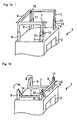
- Fig. 1a and Fig. 1b are perspective views showing an elevator cage (i.e., an elevator car) according to a first embodiment of the invention.
- Fig. 1a is a perspective view showing the state of the elevator cage of the first embodiment at the time of maintenance and inspection
- Fig. 1b is a perspective view of the elevator cage of the first embodiment in normal times.
- reference numeral 1 designates an elevator cage. Passengers get on and off or cargo is loaded or unloaded into the elevator cage by way of a door 2 (a doorway' of the car).
- Reference numeral 1a designates a cage top of the elevator cage 1.
- a fold-down safety fence i.e., a handrail device disposed on a car top
- the cage top 1a is formed flat so that a service technician can get on the cage top 1a to perform a maintenance and inspection operation.
- the safety fence provided on the cage top 1a is primarily constituted of pillar members 9, handrail members 7, and a fixing member 8.
- the side of the door 2 is opened, thereby providing an entrance for the service technician.
- These members are formed from, e.g., a steel product and bent so as to assume an L-shaped cross-sectional profile.
- the four pillar members 9 are fixed to respective corners of the cage top 1a by means of welding.
- a bracket 13 is welded to upper portions of the two pillar members 9 fastened to positions close to the door 2.
- An elongated hole into which a stepped screw 11 is to be inserted is formed in a position close to the end of each pillar member 9.
- each handrail member 7 Female threads into which the stepped screws 11 are to be screwed are formed at respective end sections of each handrail member 7, and a hole, which permits insertion of a screw 12 and fastens the same, is formed at a corner section of each handrail member 7.
- Each handrail member 7 is inserted into a space between the pillar member 9 located close to the door 2 and a rear pillar member 9 (located in a position distant from the door 2) and pivotally joined to the pillar members 9 by means of the stepped screws 11 inserted into the respective elongated holes.
- a female thread is formed at each end of the fixing member 8. The fixing member 8 can be fastened to both handrail members 7 through use of the screws 12 inserted into the respective holes.
- the fixing member 8 is fastened to the two handrail members 7 remaining upright, through use of the screws 12 for limiting pivotal movement of the handrail members 7.
- the fixing member 8 acts also as a handrail of a safety fence at the time of an operation, as do the handrail members 7.
- the service technician gets on the cage top 1a, by means of taking a space on the cage top 1a close to the door 2 as an entrance.
- the service technician When having completed maintenance and inspection, the service technician removes the fixing member 8 fastened to the handrail members 7. Next, after having been slid upward along the profiles of the elongated holes of the pillar members 9, the handrail members 7 are folded down in the directions of arrowheads shown in Fig. 1b . Subsequently, the service technician gets off the cage top 1A and fastens the fixing member 8 to the brackets 13 of the pillar members 9.
- Procedures for assembling the safety fence remaining in a normal state at the time of maintenance and inspection are the reverse of those for tucking away the safety fence.
- the fixing member 8 is attached to the brackets 13 of the right and left pillar members 9 located close to the door 2 on the cage top 1a so as to hinder the service technician from getting on the cage top 1a. More specifically, the fixing member 8 is fastened to the entrance of the safety fence, to thereby block entry of the service technician into work space. As a result, when initiating maintenance and inspection, the service technician inevitably removes the fixing member 8 provided under his/her very nose, thereby acquiring an opportunity to assemble the safety fence. Consequently, there can be obviated a chance of the service technician performing an operation while leaving the safety fence tucked away.
- Fig. 2 is a perspective view showing an elevator cage according to a second embodiment of the invention. More specifically, Fig. 2a is a perspective view of the elevator cage of the second embodiment at the time of maintenance and inspection, and Fig. 2b is a perspective view showing the elevator cage of the second embodiment in normal times.
- the second embodiment differs from the first embodiment primarily in terms of the configuration of the pillar members 9.
- a stopper 9a is provided in the middle of each pillar member 9.
- Each of the stoppers 9a is made by means of bending the base of a portion of the pillar member 9 to substantially a right angle.
- the stoppers 9a limit a rotational angle when the handrail members 7 are folded down through rotation.
- the fixing member 8 is fastened to the handrail members 7 at the time of maintenance and inspection. As shown in Fig. 2b , in normal times the fixing member 8 is housed in and tucked away at a predetermined position on the cage top 1a.
- Reference numeral 14 designates a band for bundling purpose which is a member for bundling the handrail members 7 after collapse. As a result, after having been collapsed, the handrail members 7 are fixed so as to block the entrance without fail.
- the handrail members 7 are collapsed so as to block the service technician from getting on the cage top 1a in normal times other than maintenance and inspection.
- the thus-collapsed handrail members 7 block entry of the service technician into work space.
- the service technician inevitably raises the handrail members 7 located under his/her very nose at the time of maintenance and inspection, thereby acquiring an opportunity to assemble the safety fence. Consequently, there can be obviated a chance of the service technician performing an operation while leaving the safety fence tucked away.
- Fig. 3 is a perspective view showing an elevator cage according to a third embodiment of the invention. More specifically, Fig. 3a is a perspective view of the elevator cage of the third embodiment at the time of maintenance and inspection, and Fig. 3b is a perspective view showing the elevator cage of the third embodiment in normal times.
- the third embodiment differs from the second embodiment primarily in terms of the configuration of the handrail members 7 and that of the pillar members 9.
- a member corresponding to the stopper 9a shown in Fig. 2 is not provided in the middle of each pillar member 9. Therefore, when the handrail members 7 are rotated to fall down, and the rotation of the handrail members 7 comes to a halt while the top end of the handrail member 7 remains into contact with the cage top 1a.
- the thus-collapsed handrail members 7 block entry of the service technician into work space.
- a stay 10 is welded to each handrail section 7 in substantially parallel therewith. As shown in Fig. 3b , when the handrail members 7 are collapsed, the stays 10 block generation of a scaffold for the service technician. More specifically, the handrail members 7, each having the stay 10, cover the cage top 1a, thereby blocking the work space above the cage top 1a.
- the handrail members 7 are collapsed so as to block entry of the service technician onto the cage top 1a in normal times other than maintenance and inspection, and the stays 10 are provided such that no scaffold is ensured for the service technician.
- the service technician can be reliably prevented from performing an operation on the cage top 1a while the handrail members 7 remain collapsed. Consequently, there can be obviated a chance of the service technician performing an operation while leaving the safety fence tucked away.
- Fig. 4 is a perspective view showing an elevator cage according to a fourth embodiment of the invention. More specifically, Fig. 4a is a perspective view of the elevator cage of the fourth embodiment at the time of maintenance and inspection, and Fig. 4b is a perspective view showing the elevator cage of the fourth embodiment in normal times.
- the fourth embodiment differs from the second embodiment primarily in terms of the configuration of the handrail members 7 and that of the pillar members 9. As shown in Figs. 4a and 4b , a member corresponding to the stopper 9a shown in Fig. 2 is not provided in the middle of each pillar member 9. Further, each handrail member 7 is provided so as to overlap the outside of the corresponding pillar members 9 and is joined pivotally to the pillar members 9.
- each handrail member 7 has holes, which permit insertion of the stepped screws 11 and fasten the same, are formed in respective end sections of each handrail member 7.
- the pillar members 9 are soldered to respective corners of the cage top 1a.
- a female thread into which the stepped screw 11 is to be screwed is formed in the end section of each pillar member 9.
- the handrail members 7 are pivotally joined to the pillar members 9 by means of the stepped screws 11.
- the service technician removes the fixing member 8 fastened to the handrail members 7 in the state of maintenance and inspection shown in Fig. 4a .
- the fixing member is then housed at a predetermined position.
- the service technician gets off the elevator cage 1.
- no member corresponding to the stopper 9a shown in Fig. 2 is provided.
- Fig. 4b when as the handrail members 7 are folded down, the top ends of the pillar members 7 come into contact with portions of interior walls of the respective handrail members 7. As a result, the handrails 7 do not rotate any further and remain stationary at these positions. So long as the geometries of the top ends of the pillar members 7 are made changeable, the rotation angles of the handrail members 7 can be set arbitrarily to a certain extent.
- the handrail members 7 are collapsed so as to block entry of the service technician onto the cage top 1a in normal times other than maintenance and inspection.
- the collapsed handrail members 7 block entry into work space.
- the service technician inevitably raises the handrail members 7 provided under his/her very nose, thus acquiring an opportunity to assemble the safety fence. Consequently, there can be obviated a chance of the service technician performing an operation while leaving the safety fence tucked away.
- the elevator cage according to the present invention has a fixing member removably attached to a safety fence to be assembled on a cage top, wherein the fixing member is fixed so as to block movement onto the cage top when the safety fence is folded down.
- the elevator cage according to the invention has a safety fence to be assembled on a cage top of an elevator cage, and the safety fence has pillar members and handrail members, wherein the handrail members are pivotally joined to the pillar members such that movement onto the cage is top is blocked when the handrail members are folded down .
- the service technician inevitably removes the fixing member for getting on the cage top, thereby assembling the safety fence.
- the elevator cage is useful as an elevator cage capable of preventing a service technician from falling down during maintenance and inspection operation.
- the elevator cage according to the invention has a stopper provided on each of the pillar members for limiting a rotation angle of fold-down handrail members.
- the handrail members are folded down to arbitrary positions except at the time of maintenance and inspection, thereby thoroughly preventing the service technician from getting on the cage top.
- the elevator cage is useful as an elevator cage capable of preventing a service technician from falling down during maintenance and inspection operation.
- the elevator cage according to the invention is constructed such that fold-down handrail members cover a cage top when folded down.
- the handrail members When the handrail members are folded down, no scaffold is ensured for the service technician. Therefore, the service technician initiates maintenance and inspection without forgetting to assemble a safety fence.
- the elevator cage is useful as an elevator cage capable of preventing a service technician from falling down during maintenance and inspection operation.
- the elevator system according to the invention has an elevator cage, wherein the cage has a member for hindering movement onto cage top when a safety fence provided on the cage top is folded down. There is alleviated a chance of a service technician forgetting to raise a safety fence at the initiation of maintenance and inspection.
- the elevator system is useful as an elevator system capable of preventing the service technician from falling down during maintenance and inspection operation.
Landscapes
- Maintenance And Inspection Apparatuses For Elevators (AREA)
- Cage And Drive Apparatuses For Elevators (AREA)
- Elevator Door Apparatuses (AREA)
Claims (4)
- Cage d'ascenseur (1) ayant une barrière de sécurité repliable, laquelle barrière est disposée sur un toit de cage et permet un mouvement sur le toit de cage à partir d'un côté d'une embrasure (2), dans laquelle
la barrière de sécurité a un élément de fixation (8) pouvant être attaché de façon amovible qui fixe la barrière de sécurité lorsque la barrière de sécurité est levée ; et
caractérisée en ce que
l'élément de fixation (8) est fixé dans une position proche de l'embrasure lorsque la barrière de sécurité est repliée de façon à bloquer une entrée de la barrière de sécurité. - Cage d'ascenseur (1) ayant une barrière de sécurité repliable, laquelle barrière est disposée sur un toit de cage et permet un mouvement sur le toit de cage à partir d'une embrasure (2), dans laquelle
la barrière de sécurité a des éléments formant piliers (9) fixés sur le toit et des éléments formant rampe (7) articulés de manière pivotante aux éléments formant piliers (9) ; et
caractérisée en ce que
les éléments formant rampe (7) sont formés afin de bloquer une entrée de la barrière de sécurité quand elle est repliée. - Cage d'ascenseur (1) selon la revendication 2, dans laquelle les éléments formant piliers (9) ont des butées pour limiter un angle de rotation des éléments formant rampe pivotants (7).
- Cage d'ascenseur (1) selon la revendication 2 ou 3, dans laquelle les éléments formant rampe (7) sont formés de façon à couvrir le toit de cage quand ils sont repliés.
Applications Claiming Priority (1)
| Application Number | Priority Date | Filing Date | Title |
|---|---|---|---|
| PCT/JP2001/003264 WO2002085773A1 (fr) | 2001-04-17 | 2001-04-17 | Cage d'ascenseur et ascenseur |
Publications (3)
| Publication Number | Publication Date |
|---|---|
| EP1386876A1 EP1386876A1 (fr) | 2004-02-04 |
| EP1386876A4 EP1386876A4 (fr) | 2004-06-23 |
| EP1386876B1 true EP1386876B1 (fr) | 2014-05-14 |
Family
ID=11737253
Family Applications (1)
| Application Number | Title | Priority Date | Filing Date |
|---|---|---|---|
| EP01919968.6A Expired - Lifetime EP1386876B1 (fr) | 2001-04-17 | 2001-04-17 | Barrière de securité pour ascenseur |
Country Status (4)
| Country | Link |
|---|---|
| EP (1) | EP1386876B1 (fr) |
| JP (1) | JP4839566B2 (fr) |
| CN (1) | CN1247428C (fr) |
| WO (1) | WO2002085773A1 (fr) |
Cited By (1)
| Publication number | Priority date | Publication date | Assignee | Title |
|---|---|---|---|---|
| US9764925B2 (en) | 2011-12-21 | 2017-09-19 | Otis Elevator Company | Elevator system including a car stop for maintaining overhead clearance |
Families Citing this family (21)
| Publication number | Priority date | Publication date | Assignee | Title |
|---|---|---|---|---|
| DE602004001274T2 (de) | 2003-03-31 | 2007-05-31 | Inventio Ag, Hergiswil | Haltestab für die Kreation eines zeitlichen Sicherheitsraumes in einem Aufzugsschacht |
| ATE468294T1 (de) * | 2004-04-30 | 2010-06-15 | Otis Elevator Co | Sicherheitsmerkmal für aufzugskabinenoberseite |
| WO2006087598A1 (fr) * | 2005-02-18 | 2006-08-24 | Otis Elevator Company | Longeron de toit pour cabine d'ascenseur conçu pour etre plie au moyen d'un manche actionnant tous les cotes a la fois |
| CN101031494B (zh) * | 2005-09-16 | 2010-08-25 | 三菱电机株式会社 | 电梯的轿厢上扶手装置 |
| DE102006045499A1 (de) * | 2006-09-27 | 2008-04-03 | TÜV Rheinland Industrie Service GmbH | Fahrkorbschürze mit Sicherheitsfunktion |
| KR100854232B1 (ko) * | 2006-10-16 | 2008-08-25 | 오티스 엘리베이터 컴파니 | 엘리베이터 카 |
| JP2008285266A (ja) * | 2007-05-16 | 2008-11-27 | Toshiba Elevator Co Ltd | エレベータかご上作業用安全装置 |
| ES2341070B1 (es) * | 2008-05-28 | 2011-06-10 | Orona, S.Coop. | Aparato elevador. |
| CN101948067A (zh) * | 2010-08-25 | 2011-01-19 | 康力电梯股份有限公司 | 一种可调节的轿顶护栏 |
| JP6203430B2 (ja) * | 2014-12-22 | 2017-09-27 | 三菱電機株式会社 | エレベータ装置 |
| CN107108172B (zh) * | 2015-01-05 | 2019-04-12 | 三菱电机株式会社 | 电梯装置 |
| JP6297241B1 (ja) * | 2016-07-15 | 2018-03-20 | 三菱電機株式会社 | エレベータ装置 |
| WO2018055729A1 (fr) * | 2016-09-23 | 2018-03-29 | 三菱電機株式会社 | Dispositif ascenseur |
| CN109843773B (zh) * | 2016-10-18 | 2020-08-07 | 三菱电机株式会社 | 电梯的轿厢上扶手装置 |
| DE112016007387T5 (de) * | 2016-10-27 | 2019-08-01 | Mitsubishi Electric Corporation | Obere Handlaufvorrichtung einer Aufzugskabine |
| CN109963804B (zh) * | 2016-11-15 | 2021-10-12 | 因温特奥股份公司 | 电梯轿厢 |
| CN108016974A (zh) * | 2018-01-26 | 2018-05-11 | 苏州沃诺斯精密机械有限公司 | 一种升降电梯框架 |
| CN108249263A (zh) * | 2018-01-26 | 2018-07-06 | 苏州沃诺斯精密机械有限公司 | 一种带有防护栏的电梯轿厢 |
| EP3560877A1 (fr) | 2018-04-27 | 2019-10-30 | Otis Elevator Company | Cadre de cabine d'ascenseur |
| US11554935B2 (en) | 2018-11-19 | 2023-01-17 | Inventio Ag | Elevator car |
| CN110950217B (zh) * | 2019-12-28 | 2024-03-01 | 福建快科城建增设电梯股份有限公司 | 电梯荷重沉降补偿装置及其工作方法 |
Family Cites Families (10)
| Publication number | Priority date | Publication date | Assignee | Title |
|---|---|---|---|---|
| JPS63197261A (ja) * | 1987-02-12 | 1988-08-16 | Nec Corp | バス接続方式 |
| JPS63197261U (fr) * | 1987-06-08 | 1988-12-19 | ||
| JPH0649577Y2 (ja) * | 1987-11-27 | 1994-12-14 | 株式会社日立ビルシステムサービス | エレベータの保守運転装置 |
| JP3375455B2 (ja) * | 1995-05-19 | 2003-02-10 | 三菱電機ビルテクノサービス株式会社 | 油圧エレベータのかご上安全手すり |
| JP4245209B2 (ja) * | 1998-09-03 | 2009-03-25 | 東芝エレベータ株式会社 | エレべーター |
| DE60040100D1 (de) * | 2000-12-28 | 2008-10-09 | Mitsubishi Electric Corp | Oberes kabinengeländer für aufzug |
| JP5217073B2 (ja) * | 2001-08-28 | 2013-06-19 | 三菱電機株式会社 | 乗りかご及びエレベータ装置 |
| EP1500623B1 (fr) * | 2002-05-01 | 2012-05-30 | Mitsubishi Denki Kabushiki Kaisha | Main courante pour cage d'ascenseur |
| JP2003321174A (ja) * | 2002-05-09 | 2003-11-11 | Otis Elevator Co | エレベータ乗り籠の作業用柵 |
| DE10297757T5 (de) * | 2002-06-20 | 2005-06-30 | Otis Elevator Co., Farmington | Sicherheitsaufbaubalustrade für eine Kabine eines Maschinenraum-losen Aufzugs |
-
2001
- 2001-04-17 EP EP01919968.6A patent/EP1386876B1/fr not_active Expired - Lifetime
- 2001-04-17 CN CN01811244.7A patent/CN1247428C/zh not_active Expired - Fee Related
- 2001-04-17 WO PCT/JP2001/003264 patent/WO2002085773A1/fr not_active Ceased
- 2001-04-17 JP JP2002583312A patent/JP4839566B2/ja not_active Expired - Fee Related
Cited By (1)
| Publication number | Priority date | Publication date | Assignee | Title |
|---|---|---|---|---|
| US9764925B2 (en) | 2011-12-21 | 2017-09-19 | Otis Elevator Company | Elevator system including a car stop for maintaining overhead clearance |
Also Published As
| Publication number | Publication date |
|---|---|
| EP1386876A4 (fr) | 2004-06-23 |
| CN1436147A (zh) | 2003-08-13 |
| EP1386876A1 (fr) | 2004-02-04 |
| CN1247428C (zh) | 2006-03-29 |
| JPWO2002085773A1 (ja) | 2004-08-12 |
| WO2002085773A1 (fr) | 2002-10-31 |
| JP4839566B2 (ja) | 2011-12-21 |
Similar Documents
| Publication | Publication Date | Title |
|---|---|---|
| EP1386876B1 (fr) | Barrière de securité pour ascenseur | |
| US12172876B2 (en) | Rotary telehandler with multiple ascent and descent paths | |
| EP1422185B1 (fr) | Cabine et monte-charge | |
| JP6366847B2 (ja) | エレベータのかご上手摺装置 | |
| JP2003321174A (ja) | エレベータ乗り籠の作業用柵 | |
| JPWO2007032080A1 (ja) | エレベータのかご上手摺装置 | |
| EP1481936B1 (fr) | Cage d'ascenseur comprenant une main courante placee la-dessus | |
| US6615953B1 (en) | Construction hoist with optical monitoring device | |
| JP4316984B2 (ja) | エレベータのかご上手摺り装置 | |
| JP4797563B2 (ja) | エレベータのかご上手摺装置 | |
| KR100536562B1 (ko) | 엘리베이터 케이지 및 엘리베이터 장치 | |
| JP2008297056A (ja) | 乗客コンベアの床板 | |
| JP2002362856A (ja) | エレベーターのかご上保護装置 | |
| JP3384219B2 (ja) | エレベーターの乗場開閉装置 | |
| KR102789719B1 (ko) | 사다리용 안전 케이지 | |
| JP2500938Y2 (ja) | 枠組み足場用手摺り枠 | |
| KR102707332B1 (ko) | 옹벽용 사다리 | |
| JPH02186063A (ja) | エレベータ据付用足場装置 | |
| KR200219986Y1 (ko) | 교량 점검로 출입용 사다리 | |
| JPH0826630A (ja) | エレベータのかご | |
| JP2001164858A (ja) | 可動梯子 | |
| CN120187662A (zh) | 电梯轿厢的上部扶栏以及电梯 | |
| JP2003074279A5 (fr) | ||
| JPH0840678A (ja) | エレベータ乗場出入口開口部の養生装置 | |
| JPH0867464A (ja) | 工事用エレベータ |
Legal Events
| Date | Code | Title | Description |
|---|---|---|---|
| PUAI | Public reference made under article 153(3) epc to a published international application that has entered the european phase |
Free format text: ORIGINAL CODE: 0009012 |
|
| 17P | Request for examination filed |
Effective date: 20021210 |
|
| AK | Designated contracting states |
Kind code of ref document: A1 Designated state(s): AT BE CH CY DE DK ES FI FR GB GR IE IT LI LU MC NL PT SE TR |
|
| AX | Request for extension of the european patent |
Extension state: AL LT LV MK RO SI |
|
| TPAC | Observations by third parties |
Free format text: ORIGINAL CODE: EPIDOSNTIPA |
|
| A4 | Supplementary search report drawn up and despatched |
Effective date: 20040511 |
|
| 17Q | First examination report despatched |
Effective date: 20041104 |
|
| RAP1 | Party data changed (applicant data changed or rights of an application transferred) |
Owner name: MITSUBISHI DENKI KABUSHIKI KAISHA |
|
| 17Q | First examination report despatched |
Effective date: 20041104 |
|
| GRAP | Despatch of communication of intention to grant a patent |
Free format text: ORIGINAL CODE: EPIDOSNIGR1 |
|
| INTG | Intention to grant announced |
Effective date: 20130423 |
|
| RBV | Designated contracting states (corrected) |
Designated state(s): DE FR NL |
|
| GRAS | Grant fee paid |
Free format text: ORIGINAL CODE: EPIDOSNIGR3 |
|
| GRAP | Despatch of communication of intention to grant a patent |
Free format text: ORIGINAL CODE: EPIDOSNIGR1 |
|
| INTG | Intention to grant announced |
Effective date: 20131007 |
|
| GRAA | (expected) grant |
Free format text: ORIGINAL CODE: 0009210 |
|
| AK | Designated contracting states |
Kind code of ref document: B1 Designated state(s): DE FR NL |
|
| REG | Reference to a national code |
Ref country code: DE Ref legal event code: R096 Ref document number: 60148808 Country of ref document: DE Effective date: 20140626 |
|
| REG | Reference to a national code |
Ref country code: NL Ref legal event code: VDEP Effective date: 20140514 |
|
| REG | Reference to a national code |
Ref country code: DE Ref legal event code: R097 Ref document number: 60148808 Country of ref document: DE |
|
| PG25 | Lapsed in a contracting state [announced via postgrant information from national office to epo] |
Ref country code: NL Free format text: LAPSE BECAUSE OF FAILURE TO SUBMIT A TRANSLATION OF THE DESCRIPTION OR TO PAY THE FEE WITHIN THE PRESCRIBED TIME-LIMIT Effective date: 20140514 |
|
| PLBE | No opposition filed within time limit |
Free format text: ORIGINAL CODE: 0009261 |
|
| STAA | Information on the status of an ep patent application or granted ep patent |
Free format text: STATUS: NO OPPOSITION FILED WITHIN TIME LIMIT |
|
| 26N | No opposition filed |
Effective date: 20150217 |
|
| REG | Reference to a national code |
Ref country code: DE Ref legal event code: R097 Ref document number: 60148808 Country of ref document: DE Effective date: 20150217 |
|
| REG | Reference to a national code |
Ref country code: FR Ref legal event code: ST Effective date: 20151231 |
|
| PG25 | Lapsed in a contracting state [announced via postgrant information from national office to epo] |
Ref country code: FR Free format text: LAPSE BECAUSE OF NON-PAYMENT OF DUE FEES Effective date: 20150430 |
|
| REG | Reference to a national code |
Ref country code: DE Ref legal event code: R084 Ref document number: 60148808 Country of ref document: DE |
|
| PGFP | Annual fee paid to national office [announced via postgrant information from national office to epo] |
Ref country code: DE Payment date: 20180404 Year of fee payment: 18 |
|
| REG | Reference to a national code |
Ref country code: DE Ref legal event code: R119 Ref document number: 60148808 Country of ref document: DE |
|
| PG25 | Lapsed in a contracting state [announced via postgrant information from national office to epo] |
Ref country code: DE Free format text: LAPSE BECAUSE OF NON-PAYMENT OF DUE FEES Effective date: 20191101 |