EP1388154B1 - Dispositif de commutation electrique comprenant une spire conductrice munie d'une arete saillante allongee - Google Patents
Dispositif de commutation electrique comprenant une spire conductrice munie d'une arete saillante allongee Download PDFInfo
- Publication number
- EP1388154B1 EP1388154B1 EP02732995A EP02732995A EP1388154B1 EP 1388154 B1 EP1388154 B1 EP 1388154B1 EP 02732995 A EP02732995 A EP 02732995A EP 02732995 A EP02732995 A EP 02732995A EP 1388154 B1 EP1388154 B1 EP 1388154B1
- Authority
- EP
- European Patent Office
- Prior art keywords
- contact
- arc
- contacts
- runner
- stationary
- Prior art date
- Legal status (The legal status is an assumption and is not a legal conclusion. Google has not performed a legal analysis and makes no representation as to the accuracy of the status listed.)
- Expired - Lifetime
Links
- 239000004020 conductor Substances 0.000 abstract description 26
- 210000003371 toe Anatomy 0.000 description 6
- 239000000463 material Substances 0.000 description 3
- RYGMFSIKBFXOCR-UHFFFAOYSA-N Copper Chemical compound [Cu] RYGMFSIKBFXOCR-UHFFFAOYSA-N 0.000 description 2
- PXHVJJICTQNCMI-UHFFFAOYSA-N Nickel Chemical compound [Ni] PXHVJJICTQNCMI-UHFFFAOYSA-N 0.000 description 2
- 230000015572 biosynthetic process Effects 0.000 description 2
- 239000012141 concentrate Substances 0.000 description 2
- 229910052802 copper Inorganic materials 0.000 description 2
- 239000010949 copper Substances 0.000 description 2
- 239000002184 metal Substances 0.000 description 2
- 229910052751 metal Inorganic materials 0.000 description 2
- 230000001012 protector Effects 0.000 description 2
- 229910000831 Steel Inorganic materials 0.000 description 1
- 238000002679 ablation Methods 0.000 description 1
- 239000000969 carrier Substances 0.000 description 1
- 230000006835 compression Effects 0.000 description 1
- 238000007906 compression Methods 0.000 description 1
- 238000001816 cooling Methods 0.000 description 1
- 230000003628 erosive effect Effects 0.000 description 1
- 239000007789 gas Substances 0.000 description 1
- 238000012986 modification Methods 0.000 description 1
- 230000004048 modification Effects 0.000 description 1
- 229910052759 nickel Inorganic materials 0.000 description 1
- 239000010959 steel Substances 0.000 description 1
- 230000002459 sustained effect Effects 0.000 description 1
Images


Classifications
-
- H—ELECTRICITY
- H01—ELECTRIC ELEMENTS
- H01H—ELECTRIC SWITCHES; RELAYS; SELECTORS; EMERGENCY PROTECTIVE DEVICES
- H01H9/00—Details of switching devices, not covered by groups H01H1/00 - H01H7/00
- H01H9/30—Means for extinguishing or preventing arc between current-carrying parts
- H01H9/46—Means for extinguishing or preventing arc between current-carrying parts using arcing horns
-
- H—ELECTRICITY
- H01—ELECTRIC ELEMENTS
- H01H—ELECTRIC SWITCHES; RELAYS; SELECTORS; EMERGENCY PROTECTIVE DEVICES
- H01H1/00—Contacts
- H01H1/12—Contacts characterised by the manner in which co-operating contacts engage
- H01H1/14—Contacts characterised by the manner in which co-operating contacts engage by abutting
- H01H1/22—Contacts characterised by the manner in which co-operating contacts engage by abutting with rigid pivoted member carrying the moving contact
- H01H1/221—Contacts characterised by the manner in which co-operating contacts engage by abutting with rigid pivoted member carrying the moving contact and a contact pressure spring acting between the pivoted member and a supporting member
- H01H1/226—Contacts characterised by the manner in which co-operating contacts engage by abutting with rigid pivoted member carrying the moving contact and a contact pressure spring acting between the pivoted member and a supporting member having a plurality of parallel contact bars
-
- H—ELECTRICITY
- H01—ELECTRIC ELEMENTS
- H01H—ELECTRIC SWITCHES; RELAYS; SELECTORS; EMERGENCY PROTECTIVE DEVICES
- H01H9/00—Details of switching devices, not covered by groups H01H1/00 - H01H7/00
- H01H9/30—Means for extinguishing or preventing arc between current-carrying parts
- H01H9/38—Auxiliary contacts on to which the arc is transferred from the main contacts
- H01H9/383—Arcing contact pivots relative to the movable contact assembly
Definitions
- This invention relates to electrical switching apparatus having an arc runner, which transfers the arc from separable contacts, such as arcing contacts, to an arc chute where the arc is extinguished.
- Electrical switching apparatus for power distribution systems include devices such as, for instance, circuit breakers, network protectors, transfer switches and disconnect switches.
- Power circuit breakers are typically used to connect a power distribution network to a power source. Such power circuit breakers must be able to withstand high currents for a period of time without tripping to give circuit breakers in the network time to respond and isolate the fault thereby localizing disruption of service. Thus, by the time the power circuit breaker responds, it may have to interrupt a sizable current. This results in the drawing of an arc as the circuit breaker contacts open. It is known to provide an arc chute adjacent to the opening path of the circuit breaker contacts. The arc chute is constructed of a number of spaced apart plates extending transverse to the arc. As the contacts open, the arc is transferred by electromagnetic forces to the arc plates, which cool the arc and increase the arc voltage by breaking it up into sections, both of which help to extinguish the arc.
- an arc is formed on the arcing contact and travels across a joint to the arc runner.
- the electromagnetic force on the arc may not be adequate to force the arc to cross this joint.
- One end of the arc may remain on the stationary arcing contact, severely eroding the contact. If the arc does not move onto the arc runner it will not reach the arc chute in time for the breaker to interrupt.
- U.S. Patent No. 5,969,314 discloses an air circuit breaker with multiple movable arcing contacts, in which an arc runner is employed above an integral stationary arcing contact in order to provide a surface for the arc to run toward the center of the arc chute. This elongates the arc, divides it among the arc plates and cools the arc gases, thereby extinguishing the arc and interrupting current flow.
- the arcing contacts at the center of the arc chamber part last when the circuit breaker opens, causing the arc to form in the center of the arc runner. When the arc is created on the stationary arcing contact, it is more likely to travel along a sharp edge or corner of the part.
- a longitudinal vertical slot is disposed into the center of the arc runner in order to provide an attractive edge for the arc to travel toward the center of the arc chute.
- the edge of the slot encourages the arc to travel up the center of the arc runner, engaging the arc chute near the center and extinguishing the arc sooner.
- this center slot is no more attractive to the arc than the outside edges of the arc runner.
- the arc may be attracted to the laterally extending edge of the stationary arcing contact instead of the slot in the arc runner.
- the arc has less electromagnetic drive to enter the arc chute and is more difficult to interrupt.
- the arc may run to one edge of the stationary arcing contact. This may prevent the arc from running up the arc runner.
- the arc may move to one side of the arc chamber and be less likely to enter the arc plates, possibly resulting in failure to interrupt.
- circuit breaker arc runner includes a longitudinal elongated raised ridge.
- the elongated raised ridge is preferably positioned directly above the location of arc formation and provides a prominence for concentrating electrical charge. This structure holds the arc in the center of the arc runner by providing the shortest path for the arc.
- the elongated raised ridge also provides a smooth elevated path that the arc follows up the height of the arc runner into the center of arc chute.
- an electrical switching apparatus comprises: a load terminal and a line terminal; at least one pair of separable contacts electrically connected between the load conductor and the line conductor, an operating assembly adapted for movement between an open position and a closed position to open and close the separable contacts; an arc chute positioned adjacent the separable contacts; and an arc runner electrically connected to one of the separable contacts and extending toward the arc chute to provide a path for an arc struck between the separable contacts as the separable contacts open with movement of the operating assembly from the closed position, the arc runner having a longitudinal elongated raised ridge generally laterally centered.
- the stationary arcing contact and the arc runner may comprise an electrically conductive member having a base surface in contact with the line terminal, a stationary contact surface forming the stationary arcing contact, and a runner surface leading toward the arc chute.
- the raised ridge includes a raised portion above the runner surface and a tapered portion which descends to a position proximate a surface between the stationary contact surface and the runner surface.
- the tapered portion may be above the stationary contact surface.
- the raised ridge may include a raised portion above the runner surface and a tapered portion which descends to the stationary contact surface.
- the tapered portion may be flush with the stationary contact surface.
- the stationary contact is integral with the arc runner, thereby eliminating a joint therebetween.
- an electrical switching apparatus comprises: a load conductor and a line conductor; a pair of main contacts including a movable main contact and a stationary main contact, and a separable pair of arcing contacts, including a movable arcing contact and a stationary arcing contact, the stationary main contact and the stationary arcing contact being in electrical contact with the line conductor; an operating assembly electrically connecting the movable main contact and the movable arcing contact to the load conductor, the operating assembly adapted for movement between an open position and a closed position to open and close the separable pairs of contacts, and also adapted for transitioning from closure of both the pair of main contacts and the separable pair of arcing contacts, to closure of only the separable pair of arcing contacts while the pair of main contacts are opened, to opening of the separable pair of arcing contacts in the open position thereof; an arc chute positioned adjacent the operating assembly; and an arc runner electrically connected to the stationary arcing contact
- an electrical switching apparatus comprises: a housing; a load conductor and a line conductor mounted in the housing; a pair of main contacts including a movable main contact and a stationary main contact, and a separable pair of arcing contacts, including a movable arcing contact and a stationary arcing contact, the stationary main contact and the stationary arcing contact being in electrical contact with the line conductor; a moving conductor assembly electrically connecting the movable main contact and the movable arcing contact to the load conductor and comprising a contact carrier mounted for movement between an open position and a closed position to open and close the separable pairs of contacts, at least one contact finger pivotally mounted on the contact carrier and having the movable arcing contact adjacent a free end and the movable main contact spaced from the free end, and contact spring means pivotally biasing the at least one contact finger to move from closure of only the pair of main contacts with the carrier in the closed position, to closure of both the pair of main
- the invention is applicable to electrical switching apparatus such as, for example, circuit breakers, network protectors, transfer switches and disconnect switches having separable contacts, and will be described as applied to a power circuit breaker having main and arcing contacts.
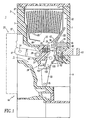
- Figures 1-3 illustrate a power air circuit breaker 1 having a housing 3 which includes a molded front casing 5 and a rear casing 7 which together define pole chambers 9 each containing a pole device 11.
- the circuit breaker 1 has three poles, one for each phase in a three-phase system.
- Figures 1-3 are vertical sections through one of the pole chambers 9 taken along slightly different lines to show the pertinent features.
- Each pole includes a line side conductor or terminal 13 which projects out of the rear casing 7 for connection to a source of alternating current (AC) electric power (not shown).
- a load conductor or terminal 15 also projects out of the rear casing 7 (see Figure 2 ) for connection typically to the conductors of a load network (not shown).
- Each pole device 11 has a pair of main contacts 17, which include a stationary main contact 19 and movable main contact 21.
- the movable main contact 21 is carried by a moving conductor assembly 23.
- This moving conductor assembly 23 includes a plurality of contact fingers 25 which are mounted in spaced axial relation on a pivot pin 27 secured in a contact carrier 29.
- the contact carrier 29 has a molded body 31 and a pair of legs 33 (both legs 33 are shown in Figure 3 ) having pivots 35 rotatably supported in the housing 3 ( Figure 3 ).
- a circuit is completed from the line conductor 13 through the closed main contacts 17, the contact fingers 25, flexible shunts 95 and the load conductor 15 (see Figure 2 ).
- the contact carrier 29 is rotated about the pivots 35 by a drive linkage 37 which includes a drive pin 39 which is received in a transverse passage 41 in the carrier body 31 through a slot 43 to which the drive pin 39 is keyed by flats 45.
- the drive pin 39 is fixed on a drive link 47, which pivots in a groove 49 ( Figures 1 and 2 ) in the carrier body 31.
- the other end of the drive link 47 is pivotally connected by a pin 51 to a pole arm 53 on a pole shaft 55 similarly connected to carriers in the other poles of the circuit breaker 1.
- the pole shaft 55 is rotated by an operating mechanism, shown schematically at 57, mounted on the front of the front casing 5 and enclosed by a cover (not shown).
- a movable main contact 21 is fixed to each of the contact fingers 25 at a point spaced from the free end of the finger.
- the portion of the contact finger 25 adjacent the free end forms a movable arcing contact or "arc toe" 59.
- the stationary arcing contact 61 which together with the arc toe 59 forms a pair of arcing contacts 63 and is provided by the exemplary integral arcing contact and runner 65.
- the moving conductor assembly 23, drive link 47 and operating mechanism 57 form an operating assembly 66 adapted for movement between an open position and a closed position to open and close the main contacts 17 and the arcing contacts 63.
- an exemplary operating assembly 66 is disclosed for movement between an open position and a closed position to open and close the separable contacts 17,63, the invention is applicable to any suitable operating assembly for opening and closing separable contacts, such as, for example, an operating assembly which moves the exemplary contact fingers 25 to open and close separable contacts.
- the integral arcing contact and runner 65 is an electrically conductive member having a base section 67 with a plurality of slots 68 and a base surface 69, an arcing contact section 71 having an arcing contact surface 73, and a runner section 75 having a runner surface 77.
- the integral arcing contact and runner 65 is a sheet metal member made of copper or steel plated with nickel, copper or other suitable material.
- the integral arcing contact and runner 65 is mounted on the line conductor 13 by a bolt 79 which extends through a support block 81, one of the slots 68 of the base section 67, the line conductor 13 and is secured by a nut 80 seated in a slot 82 in the housing 3, as shown for instance in Figure 2 .
- a support block 81 may be replaced by a suitable projection from the rear casing 7.
- a self-supporting integral arcing contact and runner may be employed without a support block.
- further support may be provided by the rear casing 7.
- slots 68 are shown in the exemplary runner 65, a wide range of one or more other openings (e.g ., holes) for fasteners may be employed.
- the integral arcing contact and runner 65 need not be bolted by the bolt 79 and nut 80 and, instead, may be suitably welded, brazed, riveted, and/or fastened by any suitable mechanical fastener.
- the arcing contact surface 73 of the integral arcing contact and runner 65 is parallel to the stationary main contact 19 but extends laterally farther toward the movable arcing contact or arc toe 59 for a purpose to be discussed.
- the runner section 75 forms an obtuse angle ⁇ ( Figure 2 ) with the arcing contact section 71 and leads upward and outward toward one side of an arc chute 83, which is positioned adjacent the arcing contacts 63.
- the sheet metal member 65 is bent by an angle 3 ( Figure 2 ) of less than 90° in forming the arcing contact section 71 and the runner section 75.
- Arc chutes such as 83 are known and include a plurality of arc plates 85 held in spaced relation by a pair of arc side plates 87 (only one is shown). At the other side of the arc chute 83 is a top arc plate 89 which extends downward and points toward the movable arcing contact 59, again for a purpose to be described.
- angle 3 is shown, the invention is applicable to larger or smaller angles (e.g ., about 0 degrees or less, in which the arc chute is not as wide as the width of the arc chute 83 and fewer arc plates 85 are employed).
- the contact fingers 25 are biased clockwise (with respect to Figures 1-3 ) by pairs of helical compression springs 91 seated in recesses 93 in the carrier body 31. Operation of the operating mechanism 57, pole shaft 55, moving conductor assembly 23 and contact carrier 29 in order to open and close the contacts 17,63 is described in U.S. Patent No. 5,969,314 , which is considered to be the closest prior art.
- the electromagnetic forces produced by the current sustained in the arc push the arc outward toward the arc chute 83 in order that the end of the arc at the stationary arcing contact 61 moves up the arcing contact section 71 of the integral arcing contact and runner 65 onto the runner section 75.
- the rapid opening of the contact carrier 29 brings the arc toes 59 adjacent the free end of the arc top plate 89 as shown in Figure 3 so that the arc extends from the arc toe 59 to that arc top plate, and moves up such arc top plate into the arc plates 85 which breaks the arc up into shorter sections.
- this stretching of the arc and braking it up into smaller sections increases the arc voltage.
- the increase in arc voltage together with the cooling of the arc by ablation of the arc plates 85, promotes interruption of the arc.
- the contact carrier 29 has a feature (recess 107 of Figure 1 ), which concentrates the are near the center of the stationary arcing contact 61, and, therefore, helps: to direct the arc toward the longitudinal elongated raised ridge 97 of Figure 4 .
- the elongated raised ridge 97 directs the arc upward toward the arc chute 83.
- the ridge 97 is preferably positioned directly above the location of arc formation and concentrates electrical charge.
- the ridge 97 holds the arc in the center of the integral arcing contact and runner 65 by providing the shortest path for the arc.
- the ridge 97 also provides a smooth elevated path that the arc follows up the height of the integral arcing contact and runner 65 into the center of arc chute 83.
- the preferred design smoothes any corners on the outride profile of the integral arcing contact and runner 65 and rounds-off the leading corner of the outside edges, such as shown at 99 of Figure 4 , in order to avoid any feature that is attractive to the arc.
- the elongated raised ridge 97 in the center of the integral arcing contact and runner 65 is preferably provided by forming the material upward ( i.e., toward the left of Figures 1-3 and 5 ) with a "semi-pierce" in the tooling that stamps the arc runner part. Also, the rounded leading corner of arc runner edges 99 are preferably provided by increasing the typical "die-roll" in the tool or by forming the material backward with a form tool.
- the elongated raised ridge 97 includes a raised portion 100 above the runner surface 77 and a tapered portion 101, which descends to a position proximate an arcuate surface 102 between the stationary contact surface 73 and the runner surface 77.
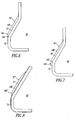
- Figures 6-8 are views similar to Figure 5 , but of respective arc runners 65', 65" and 65"' in accordance with alternative embodiments of the invention or examples useful for the understanding of the invention.
- the raised ridge 97' includes a raised portion 100' above a runner surface 77' and a tapered portion 101' which descends to the stationary contact surface 73.
- the tapered portion 101' is flush with the stationary contact surface 73.
- the elongated raised ridge 97" includes a raised portion 100" above the runner surface 77" and a proud portion 101", which protrudes above the surface 102" and above the stationary contact surface 73.
- the raised ridge 97"' includes a raised portion 100"' above the runner surface 77"' and a tapered portion 101"', which descends to a position on the runner surface 77"', which position is offset from the stationary contact surface 73.
- the stationary arcing contact 61 and the runner section 75 are integral thereby eliminating the joint between these two elements.
- This provides a single smooth surface from the point of arc creation to the top of the integral arcing contact and runner 65.
- the result is an increase in the speed of movement of the arc up the integral arcing contact and runner 65 and into the arc chute 83, even at low current levels.
- the exemplary integral arcing contact and runner 65 also has an arcuate section 98 between the arcing contact section 71 and the runner section 75 which provides the arcuate surface 102 without any sharp lateral edges which could, otherwise, divert the arc to the sides or cause hesitation in movement of the arc toward the arc chute 83.
- the tail ends 103 of the contact fingers 25 are biased by the springs 91 against a stop ledge 105 on the carrier body 31.
- the center of this stop ledge 105 has a recess 107 (see Figure 1 ) which allows the center contact fingers 25 to rotate farther clockwise than the outer contact fingers (see Figure 3 ) when the contact carrier 29 is not in the closed position. Therefore, the arcing contacts 59 on the center contact fingers 25 are the first to contact during closing. More importantly, they are the last to separate on opening so that the arc is struck primarily between the arcing contacts at the center.
- the exemplary integral arcing contact and runner 65 and the elongated raised ridge 97 improve arc interruption performance of the circuit breaker 1 at higher voltage ratings than were possible with circuit breakers with prior known arc runners.
- the exemplary elongated raised ridge 97 provides a smooth elevated path that the arc follows up the height of the integral arcing contact and runner 65 into the center of the arc chute 83. This elongated raised ridge attracts and centers the arc rather than the outside edges of the arc runner. Otherwise, the arc might hesitate before entering the arc chute.
Landscapes
- Arc-Extinguishing Devices That Are Switches (AREA)
- Breakers (AREA)
Abstract
Claims (7)
- Appareil de commutation électrique (1) comprenant au moins une paire de contacts séparables (17,63) électriquement connectés entre une borne de charge (15) et une borne de ligne (13) ;
un ensemble de manoeuvre (66) adapté pour se déplacer entre une position d'ouverture et un position de fermeture pour ouvrir et fermer lesdits contacts séparables (17, 63) ;
une boîte de soufflage (83) positionnée de manière adjacente auxdits contacts séparables (17, 63) ; et un guide d'arc (75) électriquement connecté à l'un desdits contacts séparables (17, 63) et s'étendant vers ladite boîte de soufflage (83) pour fournir un chemin pour un arc amorcé entre lesdits contacts séparables (17, 63) lorsque lesdits contacts séparables s'ouvrent avec un mouvement dudit ensemble de manoeuvre (66) de la position de fermeture,
lesdits contacts séparables (17, 63) comportant un contact d'arc fixe (61) et un contact d'arc mobile (59),
ledit contact d'arc fixe (61) et ledit guide d'arc (75) étant en contact électrique avec ladite borne de ligne (13) ;
une surface de contact fixe (73) formant ledit contact d'arc fixe (61), et une surface de guide (77, 77', 77") se dirigeant vers ladite boîte de soufflage (83) ;
l'au moins une paire de contacts séparables (17, 63) comprenant une paire de contacts principaux (17) comportant un contact principal mobile (21) et un contact principal fixe (19) et le contact d'arc fixe (61) étant solidaire du guide d'arc (75), éliminant ainsi un joint entre eux,
caractérisé en ce que le guide d'arc (75) a une arête (97, 97', 97") soulevée allongée longitudinale centrée de manière globalement latérale ;
où la crête soulevée (97, 97') comporte une partie soulevée (100, 100') au-dessus de la surface de guide (77, 77') et une partie conique (101, 101') qui descend vers la surface de contact fixe (73) ou vers une position proche d'une surface (102) entre ladite surface de contact fixe (73) et la surface de guide (77). - Appareil de commutation électrique (1) de la revendication 1, dans lequel la portion conique (101) est au-dessus de la surface de contact fixe (73) lorsque la partie conique descend vers une position proche d'une surface (102) entre ladite surface de contact fixe (73) et ladite surface de guide (77).
- Appareil de commutation électrique (1) de la revendication 2, dans lequel la partie conique (101') affleure la surface de contact fixe (73) lorsque la partie conique descend vers ladite surface de contact fixe (73).
- Appareil de commutation électrique (1) de l'une des revendications 1 à 3, dans lequel le contact fixe (61) et le guide d'arc (75) comprennent un élément électriquement conducteur (65) ayant une face de base (69) en contact avec la borne de ligne (13).
- Appareil de commutation électrique (1) de la revendication 4, dans lequel la surface de contact fixe (73) formant le contact fixe (61) et dont l'élément électriquement conducteur (65) est essentiellement transversal à la surface de base (69) et se trouve à un angle obtus par rapport à la surface de guide (77).
- Appareil de commutation électrique (1) de l'une des revendications 1 à 5, dans lequel l'ensemble de manoeuvre (66) connecte électriquement le contact principal mobile (21) et le contact d'arc mobile (59) à la borne de ligne (13) et est en outre adapté pour passer de la fermeture de la paire de contacts principaux (17) et de la paire de contacts d'arc séparables (63), à la fermeture de la seule paire de contacts d'arc séparables (63) tandis que la paire de contacts principaux (17) est ouverte, à l'ouverture de la paire de contacts d'arc séparables (63) dans sa position d'ouverture.
- Appareil de commutation électrique (1) de la revendication 6, dans lequel l'ensemble de manoeuvre (86) comporte au moins un doigt de contact (25) monté en pivotement sur un support de contact (29) et ayant le contact d'arc mobile (59) adjacent à une extrémité libre et le contact principal mobile (21) séparé de ladite extrémité libre et un moyen de ressort de contact (91) maintenant en pivotement ledit au moins un doigt de contact.
Applications Claiming Priority (3)
| Application Number | Priority Date | Filing Date | Title |
|---|---|---|---|
| US09/858,027 US6417474B1 (en) | 2001-05-15 | 2001-05-15 | Electrical switching apparatus having an arc runner with an elongated raised ridge |
| US858027 | 2001-05-15 | ||
| PCT/IB2002/001626 WO2002093601A1 (fr) | 2001-05-15 | 2002-05-13 | Dispositif de commutation electrique comprenant une spire conductrice munie d'une arete saillante allongee |
Publications (2)
| Publication Number | Publication Date |
|---|---|
| EP1388154A1 EP1388154A1 (fr) | 2004-02-11 |
| EP1388154B1 true EP1388154B1 (fr) | 2011-01-19 |
Family
ID=25327278
Family Applications (1)
| Application Number | Title | Priority Date | Filing Date |
|---|---|---|---|
| EP02732995A Expired - Lifetime EP1388154B1 (fr) | 2001-05-15 | 2002-05-13 | Dispositif de commutation electrique comprenant une spire conductrice munie d'une arete saillante allongee |
Country Status (12)
| Country | Link |
|---|---|
| US (1) | US6417474B1 (fr) |
| EP (1) | EP1388154B1 (fr) |
| CN (1) | CN100477046C (fr) |
| AR (1) | AR033733A1 (fr) |
| AU (1) | AU2002304367B8 (fr) |
| BR (1) | BR0209690A (fr) |
| CA (1) | CA2446958C (fr) |
| DE (1) | DE60238977D1 (fr) |
| ES (1) | ES2358582T3 (fr) |
| MX (1) | MXPA03010405A (fr) |
| WO (1) | WO2002093601A1 (fr) |
| ZA (1) | ZA200309646B (fr) |
Families Citing this family (32)
| Publication number | Priority date | Publication date | Assignee | Title |
|---|---|---|---|---|
| US8244370B2 (en) * | 2001-04-13 | 2012-08-14 | Greatbatch Ltd. | Band stop filter employing a capacitor and an inductor tank circuit to enhance MRI compatibility of active medical devices |
| DE19932010C1 (de) * | 1999-07-02 | 2001-03-08 | Siemens Ag | Schaltkontaktanordnung eines Niederspannungs-Leistungschalters mit Hauptkontakten, Zwischenkontakten und Abreißkontakten |
| US6747533B2 (en) * | 2001-10-11 | 2004-06-08 | Eaton Corporation | One piece air-core coil mounting bracket |
| DE10250950B4 (de) * | 2002-10-25 | 2004-10-28 | Siemens Ag | Niederspannungs-Leistungsschalter |
| US20050279734A1 (en) * | 2004-06-17 | 2005-12-22 | Carothers Arthur D | Arc runner clinch assembly for electrical switching apparatus |
| US7034242B1 (en) | 2004-11-09 | 2006-04-25 | Eaton Corporation | Arc chute and circuit interrupter employing the same |
| US6977568B1 (en) | 2005-01-13 | 2005-12-20 | Eaton Corporation | Blow open moving contact assembly for electric power switching apparatus with a very high current interruption rating |
| US7105764B2 (en) * | 2005-01-13 | 2006-09-12 | Eaton Corporation | Monolithic stationary conductor and current limiting power switch incorporating same |
| DE102005047741B4 (de) * | 2005-09-29 | 2013-02-14 | Siemens Aktiengesellschaft | Elektrischer Schalter |
| US20070095794A1 (en) * | 2005-10-28 | 2007-05-03 | Eaton Corporation | Arc plate with runner, and arc chute and electrical switching apparatus incorporating same |
| US7202436B1 (en) | 2005-10-28 | 2007-04-10 | Eaton Corporation | Secondary arc chute and electrical switching apparatus incorporating same |
| KR100817118B1 (ko) | 2006-10-17 | 2008-03-27 | 엘에스산전 주식회사 | 기중차단기의 가동접촉자 |
| US7812276B2 (en) * | 2008-04-23 | 2010-10-12 | Eaton Corporation | Electrical switching apparatus, and arc chute and arc member therefor |
| US7830232B2 (en) * | 2009-01-06 | 2010-11-09 | Eaton Corporation | Arc runner assembly and electrical switching apparatus and method incorporating same |
| WO2011128379A1 (fr) * | 2010-04-16 | 2011-10-20 | Abb Technology Ag | Chambre d'extinction d'arc pour disjoncteur, disjoncteur et procédé d'assemblage d'une chambre d'extinction d'arc |
| US8926636B2 (en) | 2010-06-10 | 2015-01-06 | Boston Scientific Scimed, Inc. | Dual offset arc needle for anchor placement of a male incontinence sling |
| DE102012110408A1 (de) * | 2012-10-31 | 2014-04-30 | Eaton Industries (Austria) Gmbh | Gleichstromschaltgerät |
| DE102013111953A1 (de) * | 2012-12-20 | 2014-06-26 | Eaton Electrical Ip Gmbh & Co. Kg | Schaltgerät |
| US9330861B2 (en) * | 2013-03-14 | 2016-05-03 | General Electric Company | Arc chute assembly for an automatic transfer switch system and methods of assembling the same |
| JP2014216078A (ja) * | 2013-04-23 | 2014-11-17 | 東洋電機製造株式会社 | 回路遮断器 |
| CN105097374B (zh) * | 2014-05-16 | 2018-01-19 | 北京人民电器厂有限公司 | 一种利于电弧快速移动和拉长的断路器 |
| ES2645855T3 (es) * | 2015-01-23 | 2017-12-11 | Abb S.P.A. | Polo interruptor de bajo voltaje |
| CN104779102A (zh) * | 2015-03-25 | 2015-07-15 | 敬德强 | 新型大电流簧片式开关触点结构 |
| US10141125B2 (en) * | 2015-04-13 | 2018-11-27 | Garrett Garcia | Contact for bus plug switches |
| US9966209B1 (en) * | 2017-02-23 | 2018-05-08 | Carling Technologies, Inc. | Circuit breaker with arc shield |
| EP3389069B1 (fr) * | 2017-04-11 | 2019-12-11 | Microelettrica Scientifica S.p.A. | Disjoncteur amélioré pour des applications à courant cc élevé ou à tension cc élevée, par exemple des applications industrielles et/ou ferroviaires |
| EP3772742B1 (fr) * | 2019-08-05 | 2025-04-23 | ABB S.p.A. | Pôle de commutation basse tension |
| CN111477473A (zh) * | 2020-06-12 | 2020-07-31 | 上海得准开电子科技有限公司 | 一种利于快速灭弧的触片结构 |
| KR102666105B1 (ko) * | 2021-05-11 | 2024-05-16 | 엘에스일렉트릭(주) | 차단부 및 이를 포함하는 기중 차단기 |
| FR3131976B1 (fr) | 2022-01-18 | 2024-06-14 | Safran Electrical & Power | Contacteur avec guides d’arc et protection intégrée aux guides d’arc, système et aéronef correspondant |
| EP4336531B1 (fr) * | 2022-09-06 | 2026-04-08 | ABB S.p.A. | Pôle de commutateur basse tension avec une chambre de rupture d'arc comprenant un couvercle pour les gaz chauds ayant une plaque et un trou traversant |
| CN119725009B (zh) * | 2023-09-28 | 2025-11-18 | 上海良信电器股份有限公司 | 一种静触头端接线排和灭弧室在开关后方设置的结构及该开关 |
Citations (2)
| Publication number | Priority date | Publication date | Assignee | Title |
|---|---|---|---|---|
| US5003137A (en) * | 1986-05-30 | 1991-03-26 | Mitsubishi Denki Kabushiki Kaisha | Switch |
| EP0444283A1 (fr) * | 1990-02-24 | 1991-09-04 | Licentia Patent-Verwaltungs-GmbH | Disjoncteur de protection de canalisation avec un appareil déclencheur |
Family Cites Families (15)
| Publication number | Priority date | Publication date | Assignee | Title |
|---|---|---|---|---|
| US2471608A (en) | 1944-04-22 | 1949-05-31 | Ite Circuit Breaker Ltd | Circuit breaker contact construction |
| DE1161350B (de) | 1961-03-13 | 1964-01-16 | Licentia Gmbh | Kontaktanordnung fuer elektrische Selbstschalter mit strombegrenzender Ausschaltcharakteristik |
| DE1690137B2 (de) * | 1968-01-31 | 1973-08-30 | Siemens AG, 1000 Berlin u 8000 München | Elektrischer leistungsschalter, insbesondere niederspannungs-leistungsschalter |
| US3662134A (en) | 1969-06-11 | 1972-05-09 | Westinghouse Electric Corp | Circuit breaker with improved current path and contact means |
| US4229630A (en) | 1980-03-17 | 1980-10-21 | Westinghouse Electric Corp. | Circuit breaker utilizing improved arc chambers |
| US4654491A (en) * | 1986-03-03 | 1987-03-31 | Westinghouse Electric Corp. | Circuit breaker with contact support and arc runner |
| US4713504A (en) | 1986-03-03 | 1987-12-15 | Westinghouse Electric Corp. | Circuit breaker with hinged arcing contact |
| KR900007273B1 (ko) * | 1986-09-16 | 1990-10-06 | 미쓰비시전기 주식회사 | 회로 차단기 |
| US5057806A (en) | 1988-08-01 | 1991-10-15 | Westinghouse Electric Corp. | Crossbar assembly |
| US4871889A (en) | 1988-09-21 | 1989-10-03 | Siemens Energy & Automation, Inc. | Arcing contact assembly for a circuit breaker |
| FR2650434B1 (fr) * | 1989-07-26 | 1995-11-24 | Merlin Gerin | Disjoncteur basse tension a contacts multiples et a fortes intensites |
| US5359161A (en) * | 1993-01-08 | 1994-10-25 | Square D Company | Non-linear spring for circuit interrupters |
| DE19643607A1 (de) * | 1996-05-13 | 1997-11-20 | Siemens Ag | Leistungsschalter für Niederspannung mit Anschlußschienen |
| US5969314A (en) | 1998-05-07 | 1999-10-19 | Eaton Corporation | Electrical switching apparatus having arc runner integral with stationary arcing contact |
| US6005206A (en) | 1998-05-07 | 1999-12-21 | Eaton Corporation | Electrical switching apparatus with improved contact arm carrier arrangement |
-
2001
- 2001-05-15 US US09/858,027 patent/US6417474B1/en not_active Expired - Lifetime
-
2002
- 2002-05-13 MX MXPA03010405A patent/MXPA03010405A/es active IP Right Grant
- 2002-05-13 WO PCT/IB2002/001626 patent/WO2002093601A1/fr not_active Ceased
- 2002-05-13 CN CNB028098501A patent/CN100477046C/zh not_active Expired - Lifetime
- 2002-05-13 DE DE60238977T patent/DE60238977D1/de not_active Expired - Lifetime
- 2002-05-13 AU AU2002304367A patent/AU2002304367B8/en not_active Ceased
- 2002-05-13 ES ES02732995T patent/ES2358582T3/es not_active Expired - Lifetime
- 2002-05-13 CA CA2446958A patent/CA2446958C/fr not_active Expired - Lifetime
- 2002-05-13 EP EP02732995A patent/EP1388154B1/fr not_active Expired - Lifetime
- 2002-05-13 BR BR0209690-0A patent/BR0209690A/pt not_active IP Right Cessation
- 2002-05-14 AR ARP020101745A patent/AR033733A1/es active IP Right Grant
-
2003
- 2003-12-11 ZA ZA200309646A patent/ZA200309646B/xx unknown
Patent Citations (2)
| Publication number | Priority date | Publication date | Assignee | Title |
|---|---|---|---|---|
| US5003137A (en) * | 1986-05-30 | 1991-03-26 | Mitsubishi Denki Kabushiki Kaisha | Switch |
| EP0444283A1 (fr) * | 1990-02-24 | 1991-09-04 | Licentia Patent-Verwaltungs-GmbH | Disjoncteur de protection de canalisation avec un appareil déclencheur |
Also Published As
| Publication number | Publication date |
|---|---|
| EP1388154A1 (fr) | 2004-02-11 |
| AR033733A1 (es) | 2004-01-07 |
| CA2446958C (fr) | 2012-05-29 |
| AU2002304367B2 (en) | 2005-10-13 |
| CN1529894A (zh) | 2004-09-15 |
| CA2446958A1 (fr) | 2002-11-21 |
| US6417474B1 (en) | 2002-07-09 |
| CN100477046C (zh) | 2009-04-08 |
| AU2002304367B8 (en) | 2006-02-09 |
| WO2002093601A1 (fr) | 2002-11-21 |
| MXPA03010405A (es) | 2004-03-09 |
| ES2358582T3 (es) | 2011-05-12 |
| BR0209690A (pt) | 2004-09-14 |
| DE60238977D1 (de) | 2011-03-03 |
| ZA200309646B (en) | 2004-09-29 |
Similar Documents
| Publication | Publication Date | Title |
|---|---|---|
| EP1388154B1 (fr) | Dispositif de commutation electrique comprenant une spire conductrice munie d'une arete saillante allongee | |
| EP0955653B1 (fr) | Appareil de commutation électrique avec cornes d'arc intégrés avec contact fixe d'arc | |
| AU2002304367A1 (en) | Electrical switching apparatus having an arc runner with an elongated raised ridge | |
| US4263492A (en) | Circuit breaker with anti-bounce mechanism | |
| US5210385A (en) | Low voltage circuit breaker with multiple contacts for high currents | |
| EP3149755B1 (fr) | Dispositif de commutation électrique, ensemble boitier de soufflage et element barriere correspondant | |
| EP2561534B1 (fr) | Interrupteur de circuit à capacités améliorées d'extinction d'arc | |
| US5184099A (en) | Circuit breaker with dual movable contacts | |
| EP4459657A2 (fr) | Appareil de commutation électrique et barrière contre les débris associée | |
| KR102169821B1 (ko) | 배선용 차단기의 아크 소호 장치 | |
| EP2048678B1 (fr) | Ensemble d'isolant gazogène et ensemble de conducteur et appareil de commutation électrique utilisant la même chose | |
| EP1471553B1 (fr) | Disjoncteur pneumatique | |
| CA1127690A (fr) | Contacts de decharge en arc doubles pour disjoncteur | |
| US5874873A (en) | Electric control apparatus | |
| US20070062912A1 (en) | Switchgear device comprising an arc chute of reduced size | |
| IE893020L (en) | Circuit breaker with low voltage contact structure | |
| US3249729A (en) | Electric circuit breaker wherein the operation of separable arcing contacts is dependent on the magnitude of current in the main contacts | |
| US4757167A (en) | Trident arc horn for circuit breaker | |
| MXPA99004244A (es) | Aparato interruptor electrico que tiene corredor de arco integral con contacto estacionario que forma arco | |
| JPH0334234A (ja) | 回路遮断器 | |
| JPH1125836A (ja) | 回路遮断器 | |
| JP4407072B2 (ja) | 回路遮断器 | |
| JPH03167728A (ja) | 回路しゃ断器 |
Legal Events
| Date | Code | Title | Description |
|---|---|---|---|
| PUAI | Public reference made under article 153(3) epc to a published international application that has entered the european phase |
Free format text: ORIGINAL CODE: 0009012 |
|
| 17P | Request for examination filed |
Effective date: 20031112 |
|
| AK | Designated contracting states |
Kind code of ref document: A1 Designated state(s): AT BE CH CY DE DK ES FI FR GB GR IE IT LI LU MC NL PT SE TR |
|
| AX | Request for extension of the european patent |
Extension state: AL LT LV MK RO SI |
|
| 17Q | First examination report despatched |
Effective date: 20040220 |
|
| GRAP | Despatch of communication of intention to grant a patent |
Free format text: ORIGINAL CODE: EPIDOSNIGR1 |
|
| RBV | Designated contracting states (corrected) |
Designated state(s): DE ES FR GB IT |
|
| GRAS | Grant fee paid |
Free format text: ORIGINAL CODE: EPIDOSNIGR3 |
|
| GRAA | (expected) grant |
Free format text: ORIGINAL CODE: 0009210 |
|
| AK | Designated contracting states |
Kind code of ref document: B1 Designated state(s): DE ES FR GB IT |
|
| REG | Reference to a national code |
Ref country code: GB Ref legal event code: FG4D |
|
| REF | Corresponds to: |
Ref document number: 60238977 Country of ref document: DE Date of ref document: 20110303 Kind code of ref document: P |
|
| REG | Reference to a national code |
Ref country code: DE Ref legal event code: R096 Ref document number: 60238977 Country of ref document: DE Effective date: 20110303 |
|
| REG | Reference to a national code |
Ref country code: ES Ref legal event code: FG2A Ref document number: 2358582 Country of ref document: ES Kind code of ref document: T3 Effective date: 20110429 |
|
| PLBE | No opposition filed within time limit |
Free format text: ORIGINAL CODE: 0009261 |
|
| STAA | Information on the status of an ep patent application or granted ep patent |
Free format text: STATUS: NO OPPOSITION FILED WITHIN TIME LIMIT |
|
| 26N | No opposition filed |
Effective date: 20111020 |
|
| REG | Reference to a national code |
Ref country code: DE Ref legal event code: R097 Ref document number: 60238977 Country of ref document: DE Effective date: 20111020 |
|
| REG | Reference to a national code |
Ref country code: FR Ref legal event code: PLFP Year of fee payment: 15 |
|
| REG | Reference to a national code |
Ref country code: FR Ref legal event code: PLFP Year of fee payment: 16 |
|
| REG | Reference to a national code |
Ref country code: FR Ref legal event code: PLFP Year of fee payment: 17 |
|
| PGFP | Annual fee paid to national office [announced via postgrant information from national office to epo] |
Ref country code: ES Payment date: 20180601 Year of fee payment: 17 |
|
| PGFP | Annual fee paid to national office [announced via postgrant information from national office to epo] |
Ref country code: GB Payment date: 20180419 Year of fee payment: 17 |
|
| REG | Reference to a national code |
Ref country code: GB Ref legal event code: 732E Free format text: REGISTERED BETWEEN 20181115 AND 20181130 |
|
| REG | Reference to a national code |
Ref country code: DE Ref legal event code: R082 Ref document number: 60238977 Country of ref document: DE Ref country code: DE Ref legal event code: R081 Ref document number: 60238977 Country of ref document: DE Owner name: EATON INTELLIGENT POWER LIMITED, IE Free format text: FORMER OWNER: EATON CORP., CLEVELAND, OHIO, US |
|
| GBPC | Gb: european patent ceased through non-payment of renewal fee |
Effective date: 20190513 |
|
| PG25 | Lapsed in a contracting state [announced via postgrant information from national office to epo] |
Ref country code: GB Free format text: LAPSE BECAUSE OF NON-PAYMENT OF DUE FEES Effective date: 20190513 |
|
| REG | Reference to a national code |
Ref country code: ES Ref legal event code: FD2A Effective date: 20200925 |
|
| PG25 | Lapsed in a contracting state [announced via postgrant information from national office to epo] |
Ref country code: ES Free format text: LAPSE BECAUSE OF NON-PAYMENT OF DUE FEES Effective date: 20190514 |
|
| PGFP | Annual fee paid to national office [announced via postgrant information from national office to epo] |
Ref country code: FR Payment date: 20210421 Year of fee payment: 20 Ref country code: DE Payment date: 20210421 Year of fee payment: 20 Ref country code: IT Payment date: 20210422 Year of fee payment: 20 |
|
| REG | Reference to a national code |
Ref country code: DE Ref legal event code: R071 Ref document number: 60238977 Country of ref document: DE |
|
| P01 | Opt-out of the competence of the unified patent court (upc) registered |
Effective date: 20230521 |