EP1391645A2 - Drehschieberventil - Google Patents
Drehschieberventil Download PDFInfo
- Publication number
- EP1391645A2 EP1391645A2 EP20030018043 EP03018043A EP1391645A2 EP 1391645 A2 EP1391645 A2 EP 1391645A2 EP 20030018043 EP20030018043 EP 20030018043 EP 03018043 A EP03018043 A EP 03018043A EP 1391645 A2 EP1391645 A2 EP 1391645A2
- Authority
- EP
- European Patent Office
- Prior art keywords
- rotary
- rotor
- mask
- valve according
- disc
- Prior art date
- Legal status (The legal status is an assumption and is not a legal conclusion. Google has not performed a legal analysis and makes no representation as to the accuracy of the status listed.)
- Granted
Links
- 239000012530 fluid Substances 0.000 claims abstract description 15
- 210000004027 cell Anatomy 0.000 claims description 44
- 210000004460 N cell Anatomy 0.000 claims description 6
- 238000005259 measurement Methods 0.000 claims description 5
- 230000002441 reversible effect Effects 0.000 claims description 3
- 230000008878 coupling Effects 0.000 description 8
- 238000010168 coupling process Methods 0.000 description 8
- 238000005859 coupling reaction Methods 0.000 description 8
- 238000004891 communication Methods 0.000 description 6
- 230000001225 therapeutic effect Effects 0.000 description 4
- 238000000034 method Methods 0.000 description 3
- 230000000712 assembly Effects 0.000 description 1
- 238000000429 assembly Methods 0.000 description 1
- 238000012840 feeding operation Methods 0.000 description 1
- 230000001052 transient effect Effects 0.000 description 1
Images


Classifications
-
- F—MECHANICAL ENGINEERING; LIGHTING; HEATING; WEAPONS; BLASTING
- F16—ENGINEERING ELEMENTS AND UNITS; GENERAL MEASURES FOR PRODUCING AND MAINTAINING EFFECTIVE FUNCTIONING OF MACHINES OR INSTALLATIONS; THERMAL INSULATION IN GENERAL
- F16K—VALVES; TAPS; COCKS; ACTUATING-FLOATS; DEVICES FOR VENTING OR AERATING
- F16K11/00—Multiple-way valves, e.g. mixing valves; Pipe fittings incorporating such valves
- F16K11/02—Multiple-way valves, e.g. mixing valves; Pipe fittings incorporating such valves with all movable sealing faces moving as one unit
- F16K11/06—Multiple-way valves, e.g. mixing valves; Pipe fittings incorporating such valves with all movable sealing faces moving as one unit comprising only sliding valves, i.e. sliding closure elements
- F16K11/072—Multiple-way valves, e.g. mixing valves; Pipe fittings incorporating such valves with all movable sealing faces moving as one unit comprising only sliding valves, i.e. sliding closure elements with pivoted closure members
- F16K11/074—Multiple-way valves, e.g. mixing valves; Pipe fittings incorporating such valves with all movable sealing faces moving as one unit comprising only sliding valves, i.e. sliding closure elements with pivoted closure members with flat sealing faces
-
- Y—GENERAL TAGGING OF NEW TECHNOLOGICAL DEVELOPMENTS; GENERAL TAGGING OF CROSS-SECTIONAL TECHNOLOGIES SPANNING OVER SEVERAL SECTIONS OF THE IPC; TECHNICAL SUBJECTS COVERED BY FORMER USPC CROSS-REFERENCE ART COLLECTIONS [XRACs] AND DIGESTS
- Y10—TECHNICAL SUBJECTS COVERED BY FORMER USPC
- Y10T—TECHNICAL SUBJECTS COVERED BY FORMER US CLASSIFICATION
- Y10T137/00—Fluid handling
- Y10T137/8593—Systems
- Y10T137/86389—Programmer or timer
-
- Y—GENERAL TAGGING OF NEW TECHNOLOGICAL DEVELOPMENTS; GENERAL TAGGING OF CROSS-SECTIONAL TECHNOLOGIES SPANNING OVER SEVERAL SECTIONS OF THE IPC; TECHNICAL SUBJECTS COVERED BY FORMER USPC CROSS-REFERENCE ART COLLECTIONS [XRACs] AND DIGESTS
- Y10—TECHNICAL SUBJECTS COVERED BY FORMER USPC
- Y10T—TECHNICAL SUBJECTS COVERED BY FORMER US CLASSIFICATION
- Y10T137/00—Fluid handling
- Y10T137/8593—Systems
- Y10T137/86389—Programmer or timer
- Y10T137/86405—Repeating cycle
-
- Y—GENERAL TAGGING OF NEW TECHNOLOGICAL DEVELOPMENTS; GENERAL TAGGING OF CROSS-SECTIONAL TECHNOLOGIES SPANNING OVER SEVERAL SECTIONS OF THE IPC; TECHNICAL SUBJECTS COVERED BY FORMER USPC CROSS-REFERENCE ART COLLECTIONS [XRACs] AND DIGESTS
- Y10—TECHNICAL SUBJECTS COVERED BY FORMER USPC
- Y10T—TECHNICAL SUBJECTS COVERED BY FORMER US CLASSIFICATION
- Y10T137/00—Fluid handling
- Y10T137/8593—Systems
- Y10T137/86389—Programmer or timer
- Y10T137/86445—Plural, sequential, valve actuations
-
- Y—GENERAL TAGGING OF NEW TECHNOLOGICAL DEVELOPMENTS; GENERAL TAGGING OF CROSS-SECTIONAL TECHNOLOGIES SPANNING OVER SEVERAL SECTIONS OF THE IPC; TECHNICAL SUBJECTS COVERED BY FORMER USPC CROSS-REFERENCE ART COLLECTIONS [XRACs] AND DIGESTS
- Y10—TECHNICAL SUBJECTS COVERED BY FORMER USPC
- Y10T—TECHNICAL SUBJECTS COVERED BY FORMER US CLASSIFICATION
- Y10T137/00—Fluid handling
- Y10T137/8593—Systems
- Y10T137/86493—Multi-way valve unit
- Y10T137/86501—Sequential distributor or collector type
Definitions
- This invention relates to rotary disc valves for feeding fluid flow and/or pressure to a plurality of ports, in particular to valves performing a predetermined cycle of feeding operations, such as, for example, numerous cyclical inflating and deflating a plurality of pressure cells in an inflatable device.
- a rotary disc valve for inflating and deflating pressure cells in a therapeutic sleeve is disclosed in US 5,014,681, incorporated herein by reference.
- This rotary disc valve comprises two discs: a stator disc with fluid flow ports connectable to a compressor and to the pressure cells, and a rotary distributor disc, the two discs contacting sealingly along a planar interfacing surface perpendicular to the axis of rotation.
- the ports of the stator disc open at the interfacing surface.
- the rotary distributor disc has a plurality of U-channels and through-going windows also opened at the interfacing surface. The channels and windows are configured so that during rotation of the rotary distributor disc, the compressor flow is successively directed, through the appropriate ports, to inflate the corresponding pressure cells, which are then successively opened to the atmosphere, all this following a predetermined sequence.
- JP 01145474 discloses a rotary disc valve with a similar function where the stator comprises two discs fixed with respect to each other, the stator discs slidingly contacting a rotor distributor disc disposed therebetween.
- the rotor disc has U-channels and through holes connecting the ports of the stator in various combinations during one turn of the rotor distributor disc.
- US 4,614,205 discloses a multiport rotary disc valve with a similar function of simultaneous interconnection of a plurality of conduits in accordance with a predetermined cycle.
- the stator and the rotary distributor in this rotary valve are assemblies each comprised of two parallel plates or discs.
- the rotary assembly is sandwiched between two parallel plates of the stator assembly.
- Crossover pipes extend between the rotor plates to form either U-channels or through-passages similar to the above-cited designs.
- the known rotary disc valves are capable of performing one predetermined cycle (sequence) of connections between the stator ports.
- the connections may be varied in time by controlling the rotational velocity and position of the rotor, but their order is determined by the pattern of the channels in the rotor and the stator.
- a multi-port rotary disc valve comprising a stator with a plurality of fluid flow ports and a rotary distributor with a plurality of channels arranged in a channel pattern.
- the channels are adapted to connect the ports between them and/or to the environment in a plurality of predetermined combinations, each combination being associated with an angular position of the rotary distributor with respect to the stator.
- a succession of such combinations performed during a full or partial unidirectional turn of the rotary distributor constitute a predetermined sequence.
- the rotary distributor comprises a rotor and a mask mounted movably thereon, accommodating the plurality of channels.
- the mask is adapted to change the channel pattern by changing its position with respect to the rotor, thereby enabling the disc valve to perform different predetermined sequences corresponding to different positions of the mask.
- the mask and the rotor are coaxial and co-rotatable discs driven by a reversible controllable electric drive.
- the rotary distributor is mounted rotatably relative to the stator in a first direction only, while the mask disc is mounted rotatably relative to the rotor disc in a second direction only, contrary to said first direction.
- the rotary distributor rotates only when electric drive rotates in the first direction and the mask disc rotates relative to the rotor disc only when the drive rotates in the second direction.
- the rotor disc has two faces, at least part of the rotary distributor channels connecting them.
- the first face sealingly contacts with a face of the stator, the connections between the stator ports and the rotary distributor channels being performed via this face.
- the second face sealingly contacts with a face of the mask disc, and the mask disc changes the channel pattern by switching connections between those channels that exit at the second face.
- the rotary disc valve used for inflating and deflating N cells comprises a central inlet port and N outlet ports disposed around the central port.
- the rotor disc has a feed channel configured so that, during one turn of the rotary distributor, it successively connects the central inlet port to each one of the outlet ports.
- the rotary disc valve is also adapted for group exhaust of all N inflated cells.
- the rotor disc has N through windows connecting the first face to the second face, configured so that, in a predetermined angular position A of the rotary distributor with respect to the stator, the N through windows match the N outlet ports.
- the mask disc has a group exhaust channel configured so that, in a predetermined angular position B of the mask disc with respect to the rotor disc, the group exhaust channel is connected to all the through windows of the rotor disc.
- the group exhaust channel is further connectable to a source of vacuum such as the entry of a compressor or pump, thereby enabling a group evacuation of any volumes connected to the N outlet ports of the stator, provided the positions A and B are attained simultaneously.
- the rotary disc valve is adapted to work as a part of a computerized system for inflating and deflating in cycles N cells connected to the N outlet ports.
- the stator of the rotary disc valve has N through pressure openings each disposed adjacent to one of the outlet ports, and a pressure channel connecting the pressure openings to a pressure outlet.
- the rotor disc has a bypass channel configured so as to be able to connect, when rotated, anyone of the outlet ports to the corresponding adjacent pressure opening while keeping the rest pressure openings stopped, thereby enabling the measurement of pressure P C in a volume connected to anyone outlet port.
- the bypass channel is disposed behind the feed channel with respect to the first direction of rotation, so that the bypass channel is connected to outlet port No.
- n when the feed channel is between outlet port No. n +1 and outlet port No. n +2, where n is an ordinal number of an outlet port, n increasing in the first direction.
- the system comprises a sensor to measure the pressure P 0 in the central inlet port, and a sensor to measure the pressure P C in the pressure outlet.
- the system is programmed to terminate the inflation of a given cell at a predetermined instant value of the pressure P 0 in order to obtain a target established pressure P E in that cell, and the system is adapted to correct this instant value in a next cycle if the measured pressure P 0 in a current cycle is different from the target pressure P E .
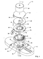
- a multi-port rotary disc valve 10 for use, for example, with an inflatable device having a plurality of pressure cells.
- inflatable device having a plurality of pressure cells.
- the device is a therapeutical massage sleeve with N annular cells embracing a human's limb (not shown here) as described in the incorporated US 5,014,681.
- the annular cells are close to each other or even slightly overlapping, and they need to be cyclically inflated or deflated in different sequences depending on the therapeutical procedure.
- the rotary disc valve 10 comprises a housing 12, a stator disc 14, a rotor disc 16, a mask disc 20, a coupling disc 22, and a drive motor 24, all adapted for coaxial assembly along axis 2 of the valve.
- the housing 12 is a massive plate with a circular recess 26 accommodating the stator 14, with a plurality of N outlet windows 28 disposed in a fan-like manner around the axis 2 at a predetermined uniform angular distance ⁇ from each other.
- the outlet windows 28 are connected by individual channels (not seen) to outlet ports 30.
- the outlet ports 30 are connected by pipes to the inflatable cells of an inflatable device, such as a massage sleeve (not shown).
- the housing 12 has also a central inlet port 32 connectable to a source of pressurized fluid such as the discharge of an air compressor (not shown), an exhaust port 34, and a vacuum port 33 connectable to a source of vacuum such as the entry of an air compressor.
- the housing also has a channel 35 for measuring the air pressure of the inlet flow and a channel 36 for measuring the air pressure in inflated cells, as will be explained in more detail below.
- the stator 14 is a disc with a wide axial opening 38 and with a plurality of various through windows, recesses and channels.
- the stator 14 has N through outlet windows 40 matching the outlet windows 28 of the housing, and N through pressure openings 46 each disposed adjacent to an outlet window 40.
- N through outlet windows 40 matching the outlet windows 28 of the housing
- N through pressure openings 46 each disposed adjacent to an outlet window 40.
- the end 47 of the cell pressure channel 44 matches the inlet of the measurement channel 36 when the stator is mounted in the housing.
- An exhaust recess 48 located to match the exhaust port 34 of the housing 12 is in fluid communication with an exhaust window 50 at the upper side of the stator (Fig. 2B), through a slit 51. Also at the upper side of the stator, which faces the rotor 16, are the entrance sides of the outlet windows 40, and a plurality of recesses 52 disposed in a fan-like manner between the outlet windows 40. The recesses 52 are displaced farther from the disc axis than the windows 40 and are internally connected to the exhaust channel 42 on the lower side of the disc.
- the pressure openings 46 connect the cell pressure channel 44 at the lower surface of the stator to the stator upper surface facing the rotor 16.
- a long arcuate recess 54 has a wide opening 56 adapted to match the vacuum port 33 in the housing 12 and is in fluid communication with the exhaust channel 42 through a slit 55.
- An extension 58 of the recess 54 is connected thereto by a narrow passage 60.
- the stator 16 is sealingly mounted to the housing 12, in the recess 50 thereof, and operates as one integral body with the housing.
- the rotor disc 16 has a blind central recess 62 at the lower side which faces the stator 14 (Fig. 3A).
- the rotor has a radial feed channel 64 extending from the recess 62 to a radius suitable to cover the outlet windows 40 on the stator 14 when the valve is assembled.
- a plurality of N+ 3 windows 66 are disposed in fan-like manner at one side of the feed channel 64. The windows 66 are at an angular distance ⁇ from each other and from the feed channel 64 so as to be able to match the windows 40 on the stator 16 when the valve is assembled.
- a group of three windows 68A, 68B, and 68C similar to the windows 66 are located at the other side of the feed channel 64.
- a group of N openings 70 are disposed between the windows 66 farther from the axis 2 of the valve than the outer edge of the windows 66.
- a single bypass recess 72 is placed in one and a half angular steps ⁇ from the feed channel 64.
- the recess 72 has such radial extent that it can cover and establish fluid communication between a window 40 and a corresponding pressure opening 46 on the stator, when the valve is assembled (shown also in Fig. 2B, in broken line).
- the rotor has also a wide window 74 completing the arc of windows 66 and 68 to a full ring.
- a wide exhaust port 76 is disposed on the rotor farther from the axis 2 than the openings 70, and is configured to match the recess 54 on the stator.
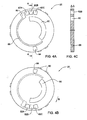
- the mask disc 20 has a wide arcuate window 80 with radial extent similar to that of the windows 66 on the rotor 16 and angular extent suitable to cover N windows 66, when the mask disc 20 is mounted on the rotor 16.
- the mask disc 20 further has a group of three adjacent exhaust windows 82A, 82B and 82C, and one remote exhaust window 84, each adapted to match the exhaust port 76 on the rotor 16.
- At the lower side of the mask facing the rotor 16 there is a group exhaust recess 86, shaped similarly to, and disposed adjacent the group of windows 82.
- the group exhaust recess 86 communicates with an arcuate exhaust channel 88 which has angular extent, radial position and width suitable to match the openings 70 and to connect them all via the exhaust recess 86, to the exhaust port 76 on the rotor, when the mask disc 20 is mounted on the rotor 16.
- an arcuate exhaust channel 88 which has angular extent, radial position and width suitable to match the openings 70 and to connect them all via the exhaust recess 86, to the exhaust port 76 on the rotor, when the mask disc 20 is mounted on the rotor 16.
- the coupling disc 22 is a thin disc with three straight teeth 92 matching the teeth 90 on the mask disc 20, and a spring pawl 94.
- the coupling disc is fixed to the shaft (not seen) of the electric motor 24.
- the electric motor 24 is reversible and controllable by angular velocity and angular coordinate.
- the control system (not shown) comprises inter alia a sensor 96 for the angular position of the rotor disc 16, and a sensor 98 for the angular position of the mask disc 20.
- the rotor 16 sits on the stator 14 and is rotatably connected to the housing 12 by means of a one-way bearing 18 allowing rotation of the rotor only in direction A.
- the mask disc 20 sits rotatably on the rotor 16.
- the coupling disc 22 engages the mask disc 20 by means of the teeth 90 and 92 for rotation of the mask in any direction.
- the spring pawl 94 of the coupling disc 22 engages the teeth 78 of the rotor disc 16 forming a ratchet mechanism allowing the mask 20 to rotate with respect to the rotor 16 only in direction B.
- the stator 14, the rotor 16, and the mask 20 are pressed to each other for air tightness by a spring means (not shown).
- the mask disc 20 and the rotor 16 rotate together, as a single body, and constitute a rotary distributor interacting with the stator 14 to feed the air coming from the air compressor to the outlet ports 30, in a predetermined sequence.
- This manner of rotation is called “operational mode”.
- the motor rotates in direction B the rotor 16 stands still with respect to the stator 14 while the mask disc 20 slips relative to the rotor 16 to change its angular position relative to the rotor, thus making a different rotary distributor capable of performing a different predetermined sequence.
- This manner of rotation is called “setup mode”.
- the inventive rotary disc valve can perform the function of several conventional multi-port disc valves.
- Sequence A Sequential inflation -simultaneous deflation.
- the mask disc 20 is rotated in direction B relative to the rotor 16 to a position where the exhaust window 84 matches the exhaust port 76, and at the same time the wide arcuate window 80 of the mask covers all N windows 66 of the rotor.
- the initial position of the rotor 16 with respect to the stator 14 is with the feed channel 64 over the exhaust window 50. This is a stand-by or idle mode where the pressurized air from the compressor comes via the central inlet port 32 and the axial opening 38 to the recess 62 and the feed channel 64, and leaves the rotary valve through the exhaust window 50 and the exhaust port 34.
- the feed channel 64 moves over the nearest outlet window 40 1 which is connected to the first annular cell, and it starts to inflate.
- the rotor moves on and the feed channel 64 now matches the nearest recess 52 1 which is connected to the exhaust channel 42, while the fluid communication with the first cell is stopped. This is also a stand-by mode.
- the rotor moves on and the feed channel matches the next outlet window 402 to inflate the next cell.
- all N cells are successively inflated until the feed channel reaches the last outlet window 40 N .
- the rotor makes about 1 ⁇ 2 turn so that all N outlet windows 40 match the windows 66 and communicate with the atmosphere via the window 80 on the mask. Thereby, the cells are deflated simultaneously and the sequence A is completed.
- Sequence B Sequential inflation - sequential deflation.
- the mask disc 20 is rotated in direction B relative to the rotor 16 to a position where the exhaust window 82A matches the exhaust port 76, and at the same time the wide arcuate window 80 of the mask covers the windows 68A, 68B and 68C of the rotor.
- the initial position of the rotor 16 with respect to the stator 14 is with the feed channel 64 over the exhaust window 50, as above.
- the feed channel 64 moves over the nearest outlet window 40 1 which is connected to the first annular cell, and it inflates. Then, the rotor moves on and the feed channel 64 matches the nearest recess 52 1 (stand-by mode). After a predetermined time, the rotor moves on and the feed channel 64 matches the next outlet window 40 2 to inflate the next cell. At the same time, the window 68A of the rotor matches the first outlet window 40 1 and the first cell releases its pressure to the atmosphere through the window 80. Thus, all N cells are successively inflated and each one is deflated when the next cell is inflated.
- the window 80 of the mask will cover only windows 68B and 68C of the rotor.
- the outlet window 40 l will be opened to the atmosphere only when the window 68B matches it, which will happen when the feed channel 64 reaches the outlet window 40 3 .
- the outlet window 40 1 openes to the atmosphere only when the window 68C matches it, and this happens when the feed channel 64 reaches the outlet window 40 4 .
- the three exhaust windows 82A, 82B and 82C of the mask with the cooperation of the three windows 68A, 68B and 68C of the rotor, provide for three sequences B each characterized by different delay of the cell deflation.
- Sequence C Active suction.
- the mask disc 20 is rotated in direction B relative to the rotor 16 to a position where the group exhaust recess 86 matches the exhaust port 76.
- the rotor 16 is now rotated, together with the mask disc 20, in direction A with respect to the stator 14 to a position where the feed channel 64 is over the exhaust window 50, in stand-by mode as above.
- the exhaust port 76 now is positioned over the arcuate recess 54 and is in fluid communication with the vacuum port 33 which is connected to the compressor entry.
- the arcuate exhaust channel 88 covers all openings 70 of the rotor which, in their turn, match the inlet windows 40. Thereby, the compressor suction provides for the rapid deflation of the massage sleeve cells.
- the rotary disc valve of the present invention may be advantageously used in a computerized system for inflating and deflating in cycles a plurality of cells connected to the outlet ports, for example in the therapeutic sleeve shown in US 5,014,681.
- the system is programmable to terminate the inflation of each cell when a predetermined instant pressure P 0 is reached (i.e. by moving the feed channel 64 to stand-by position or to the next cell).
- Another factor that may affect the established pressure P C in the cell is the inflation of the next adjacent cell, especially when the cells overlap.
- the rotary disc valve facilitates the above process of precise achievement of target established pressure P E in the inflated cells.
- the instant pressure P 0 is measured at the central inlet port of the rotary valve, by means of a pressure sensor connected to the channel 35.
- the measurement of the established cell pressure P C is provided by means of the bypass recess 72 on the rotor, which is located one-and-half angular steps ⁇ behind the feed channel 64 with respect to rotation direction A.
- the bypass recess 72 covers the first outlet window 40 and a corresponding opening 46 on the stator.
- fluid communication is provided between the first inflated cell and the cell pressure channel 44 that is connected to a pressure sensor via the measurement channel 36, and the established cell pressure P C is measured.
- the mask may be movable with respect to the rotor not only by way of rotation but in any other way providing commutation of the rotor distributor channels; the mask may comprise plural movable parts; the rotor and the mask may be driven by other means than electric motor; the rotary distributor may be driven by one motor and the mask may be driven by another motor; the discs may contact therebetween along a conical or other surface of rotation, etc.
- the stator may comprise two discs with inlet or outlet windows at either side of the rotary distributor in a manner similar to US 4,614,205 or to JP 01145474, which are incorporated herein by reference.
Landscapes
- Engineering & Computer Science (AREA)
- General Engineering & Computer Science (AREA)
- Mechanical Engineering (AREA)
- Multiple-Way Valves (AREA)
- Taps Or Cocks (AREA)
- Valve-Gear Or Valve Arrangements (AREA)
Applications Claiming Priority (2)
| Application Number | Priority Date | Filing Date | Title |
|---|---|---|---|
| US225435 | 2002-08-22 | ||
| US10/225,435 US6779557B2 (en) | 2002-08-22 | 2002-08-22 | Rotary disc valve |
Publications (3)
| Publication Number | Publication Date |
|---|---|
| EP1391645A2 true EP1391645A2 (de) | 2004-02-25 |
| EP1391645A3 EP1391645A3 (de) | 2004-03-03 |
| EP1391645B1 EP1391645B1 (de) | 2006-05-31 |
Family
ID=31187991
Family Applications (1)
| Application Number | Title | Priority Date | Filing Date |
|---|---|---|---|
| EP20030018043 Expired - Lifetime EP1391645B1 (de) | 2002-08-22 | 2003-08-07 | Drehschieberventil |
Country Status (6)
| Country | Link |
|---|---|
| US (2) | US6779557B2 (de) |
| EP (1) | EP1391645B1 (de) |
| AT (1) | ATE328230T1 (de) |
| DE (1) | DE60305588T2 (de) |
| DK (1) | DK1391645T3 (de) |
| ES (1) | ES2265078T3 (de) |
Cited By (4)
| Publication number | Priority date | Publication date | Assignee | Title |
|---|---|---|---|---|
| WO2006051280A1 (en) * | 2004-11-10 | 2006-05-18 | Huntleigh Technology Plc | Rotary valve |
| WO2017190278A1 (zh) * | 2016-05-03 | 2017-11-09 | 厦门建霖工业有限公司 | 一种水路切换机构及采用其的按钮花洒 |
| CN109026884A (zh) * | 2018-09-30 | 2018-12-18 | 合肥高益机电科技有限公司 | 一种便于安装拆卸的cbd型多路换向阀 |
| CN114754170A (zh) * | 2022-06-16 | 2022-07-15 | 成都理工大学 | 一种实现两两互通的多孔旋切阀 |
Families Citing this family (24)
| Publication number | Priority date | Publication date | Assignee | Title |
|---|---|---|---|---|
| US7156322B1 (en) * | 2003-09-22 | 2007-01-02 | Heitzman Charles J | Irrigation sprinkler unit with cycling flow rate |
| US7758523B2 (en) * | 2004-05-24 | 2010-07-20 | Kineteks Corporation | Remote sensing shoe insert apparatus, method and system |
| US20060149109A1 (en) * | 2004-12-30 | 2006-07-06 | Ruziska Philip A | Converting methanol and ethanol to light olefins |
| US7544293B2 (en) | 2005-09-26 | 2009-06-09 | Semba Inc. | Valve and process for interrupted continuous flow chromatography |
| US7377291B2 (en) * | 2005-12-28 | 2008-05-27 | Serveron Corporation | Multiport rotary valve |
| US7790040B2 (en) | 2006-08-30 | 2010-09-07 | Semba Biosciences, Inc. | Continuous isocratic affinity chromatography |
| US8807164B2 (en) * | 2006-08-30 | 2014-08-19 | Semba Biosciences, Inc. | Valve module and methods for simulated moving bed chromatography |
| US7819948B2 (en) * | 2007-10-29 | 2010-10-26 | Air Products And Chemicals, Inc. | Rotary valve |
| US8191578B2 (en) | 2007-11-13 | 2012-06-05 | Mego Afek Ac Ltd. | Rotary disc valve |
| US8196603B2 (en) | 2008-08-20 | 2012-06-12 | Semba Biosciences, Inc. | Valve block assembly |
| US9115815B2 (en) * | 2010-08-27 | 2015-08-25 | Waters Technologies Corporation | Variable-volume injection valve |
| US20140026994A1 (en) * | 2012-07-26 | 2014-01-30 | Richard N. Codos | Fluid sensing and distributing apparatus |
| US9801767B2 (en) * | 2013-03-14 | 2017-10-31 | Kap Medical, Inc. | Patient support apparatus and method |
| US9841406B2 (en) | 2013-04-22 | 2017-12-12 | Sekisui Medical Co., Ltd. | Switching valve for flow type analysis apparatus |
| US9687413B2 (en) * | 2014-02-18 | 2017-06-27 | Covidien Lp | Compression garment inflation |
| US10527192B2 (en) | 2018-02-15 | 2020-01-07 | Talis Biomedical Corporation | Rotary valve |
| US11439249B2 (en) * | 2019-01-22 | 2022-09-13 | Shang-Neng Wu | Pressure reference resetting structure of inflatable mattress |
| DE102019107296A1 (de) * | 2019-03-21 | 2020-09-24 | SWR Europe - van Dinther Antriebstechnik GmbH | Mehrwege-Drehschieberventil |
| US11008627B2 (en) | 2019-08-15 | 2021-05-18 | Talis Biomedical Corporation | Diagnostic system |
| CN111779860B (zh) * | 2020-07-02 | 2021-04-02 | 上海司羿智能科技有限公司 | 切换装置、切换组件、切换系统及其操作方法 |
| CN111728814A (zh) * | 2020-07-02 | 2020-10-02 | 上海司羿智能科技有限公司 | 转换装置、转换组件、转换系统及其操作方法 |
| US12504406B2 (en) * | 2020-09-28 | 2025-12-23 | Sekisui Chemical Co., Ltd. | Inspection chip with simplified channel switching structure |
| CN115398132B (zh) * | 2020-11-09 | 2025-10-17 | 帝肯贸易股份公司 | 在转子上具有编码器的旋转阀 |
| DE102022100987A1 (de) | 2022-01-17 | 2023-07-20 | Karlsruher Institut für Technologie | Funktionelles mikroventil |
Citations (3)
| Publication number | Priority date | Publication date | Assignee | Title |
|---|---|---|---|---|
| US4614205A (en) | 1984-12-10 | 1986-09-30 | Uop Inc. | Rotary valve with two seating surfaces for interconnecting conduits |
| JPH01145474A (ja) | 1987-11-30 | 1989-06-07 | Mitsubishi Heavy Ind Ltd | ロータリーバルブ |
| US5014681A (en) | 1989-05-05 | 1991-05-14 | Mego Afek Industrial Measuring Instruments | Method and apparatus for applying intermittent compression to a body part |
Family Cites Families (5)
| Publication number | Priority date | Publication date | Assignee | Title |
|---|---|---|---|---|
| DE3130291C2 (de) * | 1981-07-31 | 1983-10-13 | Festo-Maschinenfabrik Gottlieb Stoll, 7300 Esslingen | Schrittschaltgetriebe |
| US4478248A (en) * | 1983-01-20 | 1984-10-23 | Devall Donald L | Rotary valve |
| US5848610A (en) * | 1996-11-14 | 1998-12-15 | Livernash; Robert A. | Motorized diverter valve |
| US6257279B1 (en) * | 1997-07-07 | 2001-07-10 | Ge-Harris Railway Electronics, L.L.C. | Plural function fluid valve and method |
| US6345645B1 (en) * | 1999-12-01 | 2002-02-12 | Caretaker Systems, Inc. | Fluid distribution valve |
-
2002
- 2002-08-22 US US10/225,435 patent/US6779557B2/en not_active Ceased
-
2003
- 2003-08-07 DE DE2003605588 patent/DE60305588T2/de not_active Expired - Lifetime
- 2003-08-07 EP EP20030018043 patent/EP1391645B1/de not_active Expired - Lifetime
- 2003-08-07 AT AT03018043T patent/ATE328230T1/de not_active IP Right Cessation
- 2003-08-07 DK DK03018043T patent/DK1391645T3/da active
- 2003-08-07 ES ES03018043T patent/ES2265078T3/es not_active Expired - Lifetime
-
2006
- 2006-08-24 US US11/509,055 patent/USRE40511E1/en not_active Expired - Fee Related
Patent Citations (3)
| Publication number | Priority date | Publication date | Assignee | Title |
|---|---|---|---|---|
| US4614205A (en) | 1984-12-10 | 1986-09-30 | Uop Inc. | Rotary valve with two seating surfaces for interconnecting conduits |
| JPH01145474A (ja) | 1987-11-30 | 1989-06-07 | Mitsubishi Heavy Ind Ltd | ロータリーバルブ |
| US5014681A (en) | 1989-05-05 | 1991-05-14 | Mego Afek Industrial Measuring Instruments | Method and apparatus for applying intermittent compression to a body part |
Cited By (5)
| Publication number | Priority date | Publication date | Assignee | Title |
|---|---|---|---|---|
| WO2006051280A1 (en) * | 2004-11-10 | 2006-05-18 | Huntleigh Technology Plc | Rotary valve |
| JP2008519952A (ja) * | 2004-11-10 | 2008-06-12 | ハントリー テクノロジー ピーエルシー | ロータリーバルブ |
| WO2017190278A1 (zh) * | 2016-05-03 | 2017-11-09 | 厦门建霖工业有限公司 | 一种水路切换机构及采用其的按钮花洒 |
| CN109026884A (zh) * | 2018-09-30 | 2018-12-18 | 合肥高益机电科技有限公司 | 一种便于安装拆卸的cbd型多路换向阀 |
| CN114754170A (zh) * | 2022-06-16 | 2022-07-15 | 成都理工大学 | 一种实现两两互通的多孔旋切阀 |
Also Published As
| Publication number | Publication date |
|---|---|
| US6779557B2 (en) | 2004-08-24 |
| EP1391645B1 (de) | 2006-05-31 |
| DE60305588T2 (de) | 2007-05-10 |
| US20040035474A1 (en) | 2004-02-26 |
| EP1391645A3 (de) | 2004-03-03 |
| DE60305588D1 (de) | 2006-07-06 |
| ATE328230T1 (de) | 2006-06-15 |
| USRE40511E1 (en) | 2008-09-23 |
| ES2265078T3 (es) | 2007-02-01 |
| DK1391645T3 (da) | 2006-10-02 |
Similar Documents
| Publication | Publication Date | Title |
|---|---|---|
| US6779557B2 (en) | Rotary disc valve | |
| US8191578B2 (en) | Rotary disc valve | |
| AU756860C (en) | Rotary valve | |
| US7819948B2 (en) | Rotary valve | |
| US6355008B1 (en) | Compressed air-distributing device and valve for use in the device | |
| US7866344B2 (en) | Rotary valve | |
| JP2008519952A5 (de) | ||
| US12584566B2 (en) | Valve actuator | |
| WO2023024356A1 (zh) | 一种气垫气阀及充气床垫 | |
| WO1984001009A1 (en) | Radial vane gas throttling valve for vacuum systems | |
| AU2003215875A1 (en) | Method and apparatus for the production of mechanical power from hydraulic energy | |
| CN216479072U (zh) | 转向阀 | |
| JP4027505B2 (ja) | エアマッサージ器 | |
| JP7818087B2 (ja) | マルチ流路流体制御バルブ | |
| JPH05149101A (ja) | 圧力媒体により作動される回転駆動装置 | |
| KR20070085241A (ko) | 유체의 화학적/물리적 처리를 위한 회전식 분배기 밸브 | |
| CN203730317U (zh) | 多端口转盘泵 | |
| JPH0428952B2 (de) | ||
| DE20321320U1 (de) | Drehschieberventil | |
| JPH055401A (ja) | 共軸ロータエンジン |
Legal Events
| Date | Code | Title | Description |
|---|---|---|---|
| PUAI | Public reference made under article 153(3) epc to a published international application that has entered the european phase |
Free format text: ORIGINAL CODE: 0009012 |
|
| PUAL | Search report despatched |
Free format text: ORIGINAL CODE: 0009013 |
|
| AK | Designated contracting states |
Kind code of ref document: A2 Designated state(s): AT BE BG CH CY CZ DE DK EE ES FI FR GB GR HU IE IT LI LU MC NL PT RO SE SI SK TR |
|
| AX | Request for extension of the european patent |
Extension state: AL LT LV MK |
|
| AK | Designated contracting states |
Kind code of ref document: A3 Designated state(s): AT BE BG CH CY CZ DE DK EE ES FI FR GB GR HU IE IT LI LU MC NL PT RO SE SI SK TR |
|
| AX | Request for extension of the european patent |
Extension state: AL LT LV MK |
|
| 17P | Request for examination filed |
Effective date: 20040824 |
|
| AKX | Designation fees paid |
Designated state(s): AT BE BG CH CY CZ DE DK EE ES FI FR GB GR HU IE IT LI LU MC NL PT RO SE SI SK TR |
|
| 17Q | First examination report despatched |
Effective date: 20041111 |
|
| GRAP | Despatch of communication of intention to grant a patent |
Free format text: ORIGINAL CODE: EPIDOSNIGR1 |
|
| GRAS | Grant fee paid |
Free format text: ORIGINAL CODE: EPIDOSNIGR3 |
|
| GRAA | (expected) grant |
Free format text: ORIGINAL CODE: 0009210 |
|
| AK | Designated contracting states |
Kind code of ref document: B1 Designated state(s): AT BE BG CH CY CZ DE DK EE ES FI FR GB GR HU IE IT LI LU MC NL PT RO SE SI SK TR |
|
| PG25 | Lapsed in a contracting state [announced via postgrant information from national office to epo] |
Ref country code: IT Free format text: LAPSE BECAUSE OF FAILURE TO SUBMIT A TRANSLATION OF THE DESCRIPTION OR TO PAY THE FEE WITHIN THE PRESCRIBED TIME-LIMIT;WARNING: LAPSES OF ITALIAN PATENTS WITH EFFECTIVE DATE BEFORE 2007 MAY HAVE OCCURRED AT ANY TIME BEFORE 2007. THE CORRECT EFFECTIVE DATE MAY BE DIFFERENT FROM THE ONE RECORDED. Effective date: 20060531 Ref country code: LI Free format text: LAPSE BECAUSE OF FAILURE TO SUBMIT A TRANSLATION OF THE DESCRIPTION OR TO PAY THE FEE WITHIN THE PRESCRIBED TIME-LIMIT Effective date: 20060531 Ref country code: RO Free format text: LAPSE BECAUSE OF FAILURE TO SUBMIT A TRANSLATION OF THE DESCRIPTION OR TO PAY THE FEE WITHIN THE PRESCRIBED TIME-LIMIT Effective date: 20060531 Ref country code: SK Free format text: LAPSE BECAUSE OF FAILURE TO SUBMIT A TRANSLATION OF THE DESCRIPTION OR TO PAY THE FEE WITHIN THE PRESCRIBED TIME-LIMIT Effective date: 20060531 Ref country code: SI Free format text: LAPSE BECAUSE OF FAILURE TO SUBMIT A TRANSLATION OF THE DESCRIPTION OR TO PAY THE FEE WITHIN THE PRESCRIBED TIME-LIMIT Effective date: 20060531 Ref country code: CH Free format text: LAPSE BECAUSE OF FAILURE TO SUBMIT A TRANSLATION OF THE DESCRIPTION OR TO PAY THE FEE WITHIN THE PRESCRIBED TIME-LIMIT Effective date: 20060531 Ref country code: AT Free format text: LAPSE BECAUSE OF FAILURE TO SUBMIT A TRANSLATION OF THE DESCRIPTION OR TO PAY THE FEE WITHIN THE PRESCRIBED TIME-LIMIT Effective date: 20060531 Ref country code: CZ Free format text: LAPSE BECAUSE OF FAILURE TO SUBMIT A TRANSLATION OF THE DESCRIPTION OR TO PAY THE FEE WITHIN THE PRESCRIBED TIME-LIMIT Effective date: 20060531 Ref country code: BE Free format text: LAPSE BECAUSE OF FAILURE TO SUBMIT A TRANSLATION OF THE DESCRIPTION OR TO PAY THE FEE WITHIN THE PRESCRIBED TIME-LIMIT Effective date: 20060531 Ref country code: FI Free format text: LAPSE BECAUSE OF FAILURE TO SUBMIT A TRANSLATION OF THE DESCRIPTION OR TO PAY THE FEE WITHIN THE PRESCRIBED TIME-LIMIT Effective date: 20060531 Ref country code: NL Free format text: LAPSE BECAUSE OF FAILURE TO SUBMIT A TRANSLATION OF THE DESCRIPTION OR TO PAY THE FEE WITHIN THE PRESCRIBED TIME-LIMIT Effective date: 20060531 |
|
| REG | Reference to a national code |
Ref country code: GB Ref legal event code: FG4D Ref country code: CH Ref legal event code: EP |
|
| REG | Reference to a national code |
Ref country code: IE Ref legal event code: FG4D |
|
| REF | Corresponds to: |
Ref document number: 60305588 Country of ref document: DE Date of ref document: 20060706 Kind code of ref document: P |
|
| PG25 | Lapsed in a contracting state [announced via postgrant information from national office to epo] |
Ref country code: IE Free format text: LAPSE BECAUSE OF NON-PAYMENT OF DUE FEES Effective date: 20060808 |
|
| PG25 | Lapsed in a contracting state [announced via postgrant information from national office to epo] |
Ref country code: MC Free format text: LAPSE BECAUSE OF NON-PAYMENT OF DUE FEES Effective date: 20060831 |
|
| REG | Reference to a national code |
Ref country code: SE Ref legal event code: TRGR |
|
| REG | Reference to a national code |
Ref country code: DK Ref legal event code: T3 |
|
| PG25 | Lapsed in a contracting state [announced via postgrant information from national office to epo] |
Ref country code: PT Free format text: LAPSE BECAUSE OF FAILURE TO SUBMIT A TRANSLATION OF THE DESCRIPTION OR TO PAY THE FEE WITHIN THE PRESCRIBED TIME-LIMIT Effective date: 20061031 |
|
| NLV1 | Nl: lapsed or annulled due to failure to fulfill the requirements of art. 29p and 29m of the patents act | ||
| PLBI | Opposition filed |
Free format text: ORIGINAL CODE: 0009260 |
|
| 26 | Opposition filed |
Opponent name: ZELLERHOFF, MANFRED Effective date: 20061024 |
|
| REG | Reference to a national code |
Ref country code: CH Ref legal event code: PL |
|
| REG | Reference to a national code |
Ref country code: ES Ref legal event code: FG2A Ref document number: 2265078 Country of ref document: ES Kind code of ref document: T3 |
|
| PLAX | Notice of opposition and request to file observation + time limit sent |
Free format text: ORIGINAL CODE: EPIDOSNOBS2 |
|
| EN | Fr: translation not filed | ||
| PLAF | Information modified related to communication of a notice of opposition and request to file observations + time limit |
Free format text: ORIGINAL CODE: EPIDOSCOBS2 |
|
| PLAF | Information modified related to communication of a notice of opposition and request to file observations + time limit |
Free format text: ORIGINAL CODE: EPIDOSCOBS2 |
|
| PLBP | Opposition withdrawn |
Free format text: ORIGINAL CODE: 0009264 |
|
| PLBD | Termination of opposition procedure: decision despatched |
Free format text: ORIGINAL CODE: EPIDOSNOPC1 |
|
| GBPC | Gb: european patent ceased through non-payment of renewal fee |
Effective date: 20070807 |
|
| PG25 | Lapsed in a contracting state [announced via postgrant information from national office to epo] |
Ref country code: FR Free format text: LAPSE BECAUSE OF FAILURE TO SUBMIT A TRANSLATION OF THE DESCRIPTION OR TO PAY THE FEE WITHIN THE PRESCRIBED TIME-LIMIT Effective date: 20070309 Ref country code: GR Free format text: LAPSE BECAUSE OF FAILURE TO SUBMIT A TRANSLATION OF THE DESCRIPTION OR TO PAY THE FEE WITHIN THE PRESCRIBED TIME-LIMIT Effective date: 20060901 |
|
| PLBM | Termination of opposition procedure: date of legal effect published |
Free format text: ORIGINAL CODE: 0009276 |
|
| STAA | Information on the status of an ep patent application or granted ep patent |
Free format text: STATUS: OPPOSITION PROCEDURE CLOSED |
|
| PG25 | Lapsed in a contracting state [announced via postgrant information from national office to epo] |
Ref country code: BG Free format text: LAPSE BECAUSE OF FAILURE TO SUBMIT A TRANSLATION OF THE DESCRIPTION OR TO PAY THE FEE WITHIN THE PRESCRIBED TIME-LIMIT Effective date: 20060831 Ref country code: EE Free format text: LAPSE BECAUSE OF FAILURE TO SUBMIT A TRANSLATION OF THE DESCRIPTION OR TO PAY THE FEE WITHIN THE PRESCRIBED TIME-LIMIT Effective date: 20060531 |
|
| 27C | Opposition proceedings terminated |
Effective date: 20080323 |
|
| PG25 | Lapsed in a contracting state [announced via postgrant information from national office to epo] |
Ref country code: TR Free format text: LAPSE BECAUSE OF FAILURE TO SUBMIT A TRANSLATION OF THE DESCRIPTION OR TO PAY THE FEE WITHIN THE PRESCRIBED TIME-LIMIT Effective date: 20060531 Ref country code: HU Free format text: LAPSE BECAUSE OF FAILURE TO SUBMIT A TRANSLATION OF THE DESCRIPTION OR TO PAY THE FEE WITHIN THE PRESCRIBED TIME-LIMIT Effective date: 20061201 Ref country code: LU Free format text: LAPSE BECAUSE OF NON-PAYMENT OF DUE FEES Effective date: 20060807 |
|
| PG25 | Lapsed in a contracting state [announced via postgrant information from national office to epo] |
Ref country code: GB Free format text: LAPSE BECAUSE OF NON-PAYMENT OF DUE FEES Effective date: 20070807 Ref country code: CY Free format text: LAPSE BECAUSE OF FAILURE TO SUBMIT A TRANSLATION OF THE DESCRIPTION OR TO PAY THE FEE WITHIN THE PRESCRIBED TIME-LIMIT Effective date: 20060531 Ref country code: FR Free format text: LAPSE BECAUSE OF FAILURE TO SUBMIT A TRANSLATION OF THE DESCRIPTION OR TO PAY THE FEE WITHIN THE PRESCRIBED TIME-LIMIT Effective date: 20060531 |
|
| PGFP | Annual fee paid to national office [announced via postgrant information from national office to epo] |
Ref country code: SE Payment date: 20090806 Year of fee payment: 7 |
|
| PGFP | Annual fee paid to national office [announced via postgrant information from national office to epo] |
Ref country code: ES Payment date: 20100915 Year of fee payment: 8 |
|
| PGFP | Annual fee paid to national office [announced via postgrant information from national office to epo] |
Ref country code: DE Payment date: 20100812 Year of fee payment: 8 |
|
| PGFP | Annual fee paid to national office [announced via postgrant information from national office to epo] |
Ref country code: DK Payment date: 20100812 Year of fee payment: 8 |
|
| EUG | Se: european patent has lapsed | ||
| REG | Reference to a national code |
Ref country code: DK Ref legal event code: EBP |
|
| REG | Reference to a national code |
Ref country code: DE Ref legal event code: R119 Ref document number: 60305588 Country of ref document: DE Effective date: 20120301 |
|
| PG25 | Lapsed in a contracting state [announced via postgrant information from national office to epo] |
Ref country code: DK Free format text: LAPSE BECAUSE OF NON-PAYMENT OF DUE FEES Effective date: 20110831 |
|
| PG25 | Lapsed in a contracting state [announced via postgrant information from national office to epo] |
Ref country code: SE Free format text: LAPSE BECAUSE OF NON-PAYMENT OF DUE FEES Effective date: 20100808 |
|
| REG | Reference to a national code |
Ref country code: ES Ref legal event code: FD2A Effective date: 20130604 |
|
| PG25 | Lapsed in a contracting state [announced via postgrant information from national office to epo] |
Ref country code: DE Free format text: LAPSE BECAUSE OF NON-PAYMENT OF DUE FEES Effective date: 20120301 |
|
| PG25 | Lapsed in a contracting state [announced via postgrant information from national office to epo] |
Ref country code: ES Free format text: LAPSE BECAUSE OF NON-PAYMENT OF DUE FEES Effective date: 20110808 |