EP1396194B1 - Vorrichtung zum Erzeugen von Speiseeis - Google Patents
Vorrichtung zum Erzeugen von Speiseeis Download PDFInfo
- Publication number
- EP1396194B1 EP1396194B1 EP03020246A EP03020246A EP1396194B1 EP 1396194 B1 EP1396194 B1 EP 1396194B1 EP 03020246 A EP03020246 A EP 03020246A EP 03020246 A EP03020246 A EP 03020246A EP 1396194 B1 EP1396194 B1 EP 1396194B1
- Authority
- EP
- European Patent Office
- Prior art keywords
- mixing blade
- evaporator coil
- container
- inner container
- drive shaft
- Prior art date
- Legal status (The legal status is an assumption and is not a legal conclusion. Google has not performed a legal analysis and makes no representation as to the accuracy of the status listed.)
- Expired - Lifetime
Links
- 235000015243 ice cream Nutrition 0.000 title claims abstract description 17
- 239000000463 material Substances 0.000 claims description 11
- 230000013011 mating Effects 0.000 claims description 8
- 230000005540 biological transmission Effects 0.000 claims description 4
- 238000005057 refrigeration Methods 0.000 claims description 3
- 238000007789 sealing Methods 0.000 claims description 2
- 239000013013 elastic material Substances 0.000 claims 1
- 230000002596 correlated effect Effects 0.000 abstract 1
- 230000015572 biosynthetic process Effects 0.000 description 4
- 238000010521 absorption reaction Methods 0.000 description 3
- RYGMFSIKBFXOCR-UHFFFAOYSA-N Copper Chemical compound [Cu] RYGMFSIKBFXOCR-UHFFFAOYSA-N 0.000 description 2
- LFQSCWFLJHTTHZ-UHFFFAOYSA-N Ethanol Chemical compound CCO LFQSCWFLJHTTHZ-UHFFFAOYSA-N 0.000 description 2
- 229910052802 copper Inorganic materials 0.000 description 2
- 239000010949 copper Substances 0.000 description 2
- 239000011888 foil Substances 0.000 description 2
- 239000007789 gas Substances 0.000 description 2
- 229910052782 aluminium Inorganic materials 0.000 description 1
- XAGFODPZIPBFFR-UHFFFAOYSA-N aluminium Chemical compound [Al] XAGFODPZIPBFFR-UHFFFAOYSA-N 0.000 description 1
- 238000004140 cleaning Methods 0.000 description 1
- 238000007906 compression Methods 0.000 description 1
- 230000006835 compression Effects 0.000 description 1
- 239000004020 conductor Substances 0.000 description 1
- 230000008878 coupling Effects 0.000 description 1
- 238000010168 coupling process Methods 0.000 description 1
- 238000005859 coupling reaction Methods 0.000 description 1
- 230000001419 dependent effect Effects 0.000 description 1
- 238000000151 deposition Methods 0.000 description 1
- 239000006185 dispersion Substances 0.000 description 1
- 238000009472 formulation Methods 0.000 description 1
- 239000007788 liquid Substances 0.000 description 1
- 229910052751 metal Inorganic materials 0.000 description 1
- 239000002184 metal Substances 0.000 description 1
- 239000000203 mixture Substances 0.000 description 1
- 238000012856 packing Methods 0.000 description 1
- 230000002093 peripheral effect Effects 0.000 description 1
- 230000000750 progressive effect Effects 0.000 description 1
Images


Classifications
-
- A—HUMAN NECESSITIES
- A23—FOODS OR FOODSTUFFS; TREATMENT THEREOF, NOT COVERED BY OTHER CLASSES
- A23G—COCOA; COCOA PRODUCTS, e.g. CHOCOLATE; SUBSTITUTES FOR COCOA OR COCOA PRODUCTS; CONFECTIONERY; CHEWING GUM; ICE-CREAM; PREPARATION THEREOF
- A23G9/00—Frozen sweets, e.g. ice confectionery, ice-cream; Mixtures therefor
- A23G9/04—Production of frozen sweets, e.g. ice-cream
- A23G9/22—Details, component parts or accessories of apparatus insofar as not peculiar to a single one of the preceding groups
- A23G9/225—Ice-cream freezing and storing cabinets
- A23G9/227—Details
-
- A—HUMAN NECESSITIES
- A23—FOODS OR FOODSTUFFS; TREATMENT THEREOF, NOT COVERED BY OTHER CLASSES
- A23G—COCOA; COCOA PRODUCTS, e.g. CHOCOLATE; SUBSTITUTES FOR COCOA OR COCOA PRODUCTS; CONFECTIONERY; CHEWING GUM; ICE-CREAM; PREPARATION THEREOF
- A23G9/00—Frozen sweets, e.g. ice confectionery, ice-cream; Mixtures therefor
- A23G9/04—Production of frozen sweets, e.g. ice-cream
- A23G9/08—Batch production
- A23G9/12—Batch production using means for stirring the contents in a non-moving container
-
- A—HUMAN NECESSITIES
- A23—FOODS OR FOODSTUFFS; TREATMENT THEREOF, NOT COVERED BY OTHER CLASSES
- A23G—COCOA; COCOA PRODUCTS, e.g. CHOCOLATE; SUBSTITUTES FOR COCOA OR COCOA PRODUCTS; CONFECTIONERY; CHEWING GUM; ICE-CREAM; PREPARATION THEREOF
- A23G9/00—Frozen sweets, e.g. ice confectionery, ice-cream; Mixtures therefor
- A23G9/04—Production of frozen sweets, e.g. ice-cream
- A23G9/22—Details, component parts or accessories of apparatus insofar as not peculiar to a single one of the preceding groups
- A23G9/224—Agitators or scrapers
-
- A—HUMAN NECESSITIES
- A23—FOODS OR FOODSTUFFS; TREATMENT THEREOF, NOT COVERED BY OTHER CLASSES
- A23G—COCOA; COCOA PRODUCTS, e.g. CHOCOLATE; SUBSTITUTES FOR COCOA OR COCOA PRODUCTS; CONFECTIONERY; CHEWING GUM; ICE-CREAM; PREPARATION THEREOF
- A23G9/00—Frozen sweets, e.g. ice confectionery, ice-cream; Mixtures therefor
- A23G9/04—Production of frozen sweets, e.g. ice-cream
- A23G9/22—Details, component parts or accessories of apparatus insofar as not peculiar to a single one of the preceding groups
- A23G9/225—Ice-cream freezing and storing cabinets
Definitions
- the present invention concerns a device to produce ice-cream for ice-cream producing machines.
- the present invention is applied to ice-cream producing machines of a domestic or semi-professional type.
- Machines of a domestic or semi-professional type wherein the container where the ice-cream is formed cooperates with a mixing blade and with means to transfer the cold, or heat absorption means.
- the mixing blade takes motion from drive means associated with the cover.
- the blade takes motion from drive means located under or at the side of the container and connected to the mixing blade by a drive shaft which passes axially to the container with a cylindrical design.
- the drive means can be electric or manually driven.
- a first design philosophy provides a fixed evaporator coil, that is, a coil wherein the temperature of the compressed gas goes down as it expands, which is cylindrical in shape; the coil surrounds the container and leaves an interspace between the coil and the container for the operations to insert and remove the container itself.
- a second design philosophy has conceived of an elastic evaporator coil equipped with clamping means, as shown for example in US-A-4.573.329 and in EP-A-129.706 .
- the evaporator coil opens or closes radially, so that it is possible to insert (or remove) the container by extracting it axially from the coil.
- the clamping means are activated and the evaporator coil contracts radially, surrounding, and closely connecting with, the peripheral cylindrical body of the container.
- This system guarantees an optimum heat absorption, but it has the drawbacks of the high cost of the evaporator coil and of the fact that it is easily damaged even by a careful user, and even more so by an inattentive user.
- Damage to the coil can also entail a dispersion into the environment of dangerous refrigeration gases.
- a system is also known, from JP-A-02-145153 and from JP-A-02-100634 , which provides that it is the container that is pressed elastically against the rotating mixing blade, by a coil located below.
- the fact that the inside of the container and the mixing blade are held pressed against each other is important in order to prevent the formation of ice in the cooled zone, as any formation of ice would reduce the heat exchange.
- the document DE 3 806 508 discloses a domestic ice cream mixer in which the mixing blade is pushed elastically against the bottom of the container.
- Applicant therefore set himself the problem of finding an optimum solution to these problems and surprisingly found, and also studied, experimented and embodied the present invention.
- the purpose of the present invention is therefore to improve the behavior of the mixing blade, which not only performs the known function of mixing and introducing air into the ice-cream, but thus performs the function of continuously raising the material, so that the cold transmitted to the bottom of the container and, from this, to the material in contact, is continuously carried upwards with a progressive uniformization of the temperature of the product.
- the mixing blade is shaped so as to cooperate elastically with the bottom of the ice-cream container, so as to prevent the formation of ice.
- the invention has set itself the aim of preventing dangers for the operator in the event that the cover is removed and at the same time the blade is left in motion, so that it continues to rotate.
- the size of the container that is, the ratio between the usable inner diameter and the height of the level of product which can be obtained (that is, the ice-cream) improves the performance of the device according to the invention.
- this ratio is between 0.30 and 0.50, advantageously between 0.38 and 0.42.
- the contact between the intermediate plate with the container and the evaporator coil must always be kept constant, and this constant contact is maintained by a conductive paste or other suitable plastic material, located in cooperation with the coil.
- the contact between the container and the plate-coil system is maintained elastically due to the elastic thrust towards the container of the evaporator coil while the container remains fixed, in the working phase.
- the evaporator coil deforms elastically according to the thrust that it receives towards the container; this improves the heat yield.
- the coil is incorporated into a melted material, such as copper, aluminum or suchlike or into said conductive paste, in order to improve the distribution and uniformity of the cold.
- the device 10 is composed of a containing unit 11, or outer container, having a housing compartment 12, a supporting edge 13, a supporting and contrasting edge 113 and a cover 26.
- an inner container 14 hereafter simply container, having a positioning edge 15, a cylindrical body 16, a bottom 17 and an axial guide tube 18.
- the bottom 17 is flat and connects with the cylindrical body 16.
- the container 14 includes an inner compartment 114.
- the drive shaft 19 moves and rotates, in a protected position, inside the guide tube 18, driven by drive means not shown here since they are already known, which gives motion to the mixing blade 20.
- the bottom 17 is flat on the outside and cooperates with an evaporator coil 21 and with a base 25, through mating contact surfaces, upper 27 and lower 127.
- the upper contact surface 27 is pressed against the bottom 17 of the container 14 by a plurality of elastic means 22, in this case helical springs, which rest on the bottom of the housing compartment 12.
- the evaporator coil 21, in this case, consists of a supporting and transmission plate or foil 23, a coil element 24 and a base or support 25, heat insulated towards the bottom.
- the elastic means 22 press on the base 25.
- the coil element 24 is connected to the refrigeration system of the machine.
- the evaporator coil 21 operates only on the bottom 17.
- the evaporator coil 21 also operates on the rounded edge 117 of the container 14.
- the plate or foil 23 is made of heat conductive material, so as not to impede the heat exchange and at the same time make it possible to clean the compartment 12.
- the base or support 25 is advantageously made of plastic.
- the coil element 24 is made of copper pipe with a limited thickness in order to improve the heat exchange.
- the coil element 24, after being conformed according to the geometric development of the exchange surface of the container 14, can be subjected to a heading action able to create at least an upper contact surface 27, and advantageously a lower contact surface 127 too.
- the contact surfaces 27, 127 include a plane segment which increases the heat exchange surface.
- the springs 22 can be metal or plastic material and can consist of a plurality of ring-shaped elements, or of a single ring-shaped element; they achieve an overall thrust of between 20 and 60 kg, advantageously 35 ⁇ 45 kg.
- the coil element 24 deforms in an elastic field, guaranteeing an improved contact.
- the drive shaft 19 is connected at the upper part in a known manner and can be removed from the mixing blade 20.
- the mixing blade 20 has a scraper fin 120 that cooperates with the part of the inner compartment 114 that is directly involved in the heat exchange, in order to prevent the formation of ice.
- the mixing blade 20 has a sealing packing 28, possibly with a cleaning function, which prevents any material from depositing between the blade 20 and the axial guide tube 18 of the container 14.
- the drive shaft 19 has key means 30 on its upper part which cooperate with a seating 31 present in the mixing blade 20, the means 30 and 31 allowing the blade 20 to be axially removed with ease.
- the drive shaft 19 cooperates at the upper part with a removable knob 32, which acts on spring means 33 which abut axially on the mixing blade 20, obliging it to remain pressed against the bottom 17.
- the mixing blade 20 cooperates at the upper part, through a seating 34, with the cover 26.
- the elasticity of the scraper fin 120 that is, of those blades that act on the bottom 17, creates the desired continuous elastic contact.
- the cover 26 is anchored to the outer container 11 by means of a rotation system which provides one or more approaching ramps in order to simplify and make closing less difficult for the operator.
- the approaching ramps determine the reciprocal axial position of the cover 26 with respect to the outer container 11.
- the operator can therefore determine the reciprocal position of the outer container 11 and the cover 26. This means that in relation to the conformation of the ramps, that is, the circumferential position of the cover 26 with respect to the ramps, a greater or lesser compression is determined of the container 14 on the evaporator coil 21 and hence a greater or lesser adhesion between the reciprocal contact surfaces.
- the container 14 has the following ratios if we assume the diameter D as 1; H, that is, the total height of the container is 0.55; h, that is, the usable height for the level of ice-cream is between 0.30 and 0.50, advantageously between 0.38 and 0.42, in this case 0.37.
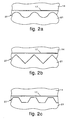
- the coupling between the bottom 17 of the container 14 and the mating upper contact surface 27 of the coil 21 can assume various forms, such as rings having a geometric profile (wavy, V-shaped, fretted, etc.) ( figs. 2a, 2b and 2c ), arc-shaped ( fig. 3a ), inner V-shaped ( fig. 3b ) or outer V-shaped ( fig. 3c ) .
Landscapes
- Engineering & Computer Science (AREA)
- Life Sciences & Earth Sciences (AREA)
- Chemical & Material Sciences (AREA)
- Food Science & Technology (AREA)
- Polymers & Plastics (AREA)
- Manufacturing & Machinery (AREA)
- Confectionery (AREA)
Claims (11)
- Vorrichtung zum Herstellen von Speiseeis für Speiseeis herstellende Maschinen des Typs zum Hausgebrauch oder zum semiprofessionellen Einsatz, die mit einer Kühleinheit zusammenwirkt und bei der ein äußerer Behälter (11), eine Abdeckung (26), ein innerer Behälter (14) mit einem Axialrohr (18), eine Mischschaufel (20), die eine Schabrippe (120) aufweist, und eine Verdampferrohrschlange (21) zum Abführen von Wärme aus dem inneren Behälter (14) sowie hierüber von dem darin vorhandenen Material vorhanden sind, wobei die Mischschaufel (20) im oberen Teil in axial entfernbarer Art und Weise mit einer Antriebswelle (19) gekoppelt ist, die durch Antriebsmittel in Drehung versetzbar ist und die in das Axialrohr (18) eingeführt ist, wobei die Verdampferrohrschlange (21) über wenigstens eine Kontaktoberfläche (27) mit dem Boden (17) des inneren Behälters (14) zusammenwirkend angeordnet ist, dadurch gekennzeichnet, dass wenigstens die Schabrippe (120) aus einem elastischen Material hergestellt ist und dass die Mischschaufel (20) über eine Aufnahme (34) zum unmittelbaren axialen Zusammenwirken mit der sich drehenden Abdeckung (26) eingerichtet ist, um durch die Abdeckung (26) axial gegen den Boden des inneren Behälters (14) unter Ausnutzen der Elastizität der Schabrippe geschoben zu werden, wenn diese in einer geschlossenen Stellung ist.
- Vorrichtung nach Anspruch 1, dadurch gekennzeichnet, dass die Mischschaufel (20) mit der Antriebswelle (19) über Passmittel (30) verbunden ist, die mit einer Aufnahme (31) zusammenwirken, um axial in Bezug auf die Antriebswelle (19) gleiten zu können, und dass der freie axiale Weg der Mischschaufel (20) größer als die Länge des umfänglichen Verbindungssegments (30, 31) zwischen der Schaufel (20) und der Antriebswelle (19) ist, so dass bei Fehlen des Schubs der Abdeckung (26) die Mischschaufel (20) auf eine natürliche Art und Weise axial von der Antriebswelle (19) entfernt werden kann, um dadurch die Übertragung der Bewegung zu unterbrechen.
- Vorrichtung nach Anspruch 1, dadurch gekennzeichnet, dass die aufeinander angepassten Kontaktoberflächen (27) des Bodens (17) und der Verdampferrohrschlange (21) flach sind.
- Vorrichtung nach Anspruch 1, dadurch gekennzeichnet, dass die aufeinander angepassten Kontaktoberflächen (27) des Bodens (17) und der Verdampferrohrschlange (21) über eine Anzahl von Ringen verfügen, die ein geometrisches Profil (gewellt, V-förmig und dergleichen) aufweisen.
- Vorrichtung nach Anspruch 1, dadurch gekennzeichnet, dass die aufeinander angepassten Kontaktoberflächen (27) des Bodens (17) und der Verdampferrohrschlange (21) eine bogenartige Ausbildung aufweisen.
- Vorrichtung nach Anspruch 1, dadurch gekennzeichnet, dass die aufeinander angepassten Kontaktoberflächen (27) des Bodens (17) und der Verdampferrohrschlange (21) eine V-förmige Ausbildung (nach innen oder nach außen) aufweisen.
- Vorrichtung nach einem der vorangehenden Ansprüche, dadurch gekennzeichnet, dass der Durchmesser des Bodens (17) im Verhältnis zu der durch das Speiseeis eingenommenen Höhe in dem inneren Behälter (14) innerhalb eines Bereichs liegt, der von etwa 0,30 bis etwa 0,50, vorzugsweise zwischen etwa 0,38 bis etwa 0,42, reicht.
- Vorrichtung nach einem der vorangehenden Ansprüche, dadurch gekennzeichnet, dass die Verdampferrohrschlange (21) über ein Rohrschlangenelement (24) verfügt, das aus einem Material ausgeführt ist, das einen hohen Wärmeleitkoeffzienten aufweist.
- Vorrichtung nach einem der vorangehenden Ansprüche, dadurch gekennzeichnet, dass die Mischschaufel (20) so ausgebildet ist, dass sie in dem inneren Behälter (14) vorhandenes Material nach oben schiebt.
- Vorrichtung nach einem der vorangehenden Ansprüche, dadurch gekennzeichnet, dass die Antriebswelle (19) an ihrem oberen Ende einen entfernbaren Knebel (32) aufweist, der mit Federmitteln (33) zusammenwirkt, um einen axialen Schub auf die Mischschaufel (20) auszuüben.
- Vorrichtung nach einem der vorangehenden Ansprüche, dadurch gekennzeichnet, dass der innere Teil der Mischschaufel (20) über Abdichtmittel (28) verfügt, die mit dem Axialrohr (18) zusammenwirken.
Applications Claiming Priority (2)
| Application Number | Priority Date | Filing Date | Title |
|---|---|---|---|
| IT000190A ITUD20020190A1 (it) | 2002-09-09 | 2002-09-09 | Dispositivo per la produzione di gelato |
| ITUD20020190 | 2002-09-09 |
Publications (2)
| Publication Number | Publication Date |
|---|---|
| EP1396194A1 EP1396194A1 (de) | 2004-03-10 |
| EP1396194B1 true EP1396194B1 (de) | 2009-03-18 |
Family
ID=31503971
Family Applications (2)
| Application Number | Title | Priority Date | Filing Date |
|---|---|---|---|
| EP03020265A Expired - Lifetime EP1396195B1 (de) | 2002-09-09 | 2003-09-08 | Vorrichtung zum Erzeugen von Speiseeis |
| EP03020246A Expired - Lifetime EP1396194B1 (de) | 2002-09-09 | 2003-09-08 | Vorrichtung zum Erzeugen von Speiseeis |
Family Applications Before (1)
| Application Number | Title | Priority Date | Filing Date |
|---|---|---|---|
| EP03020265A Expired - Lifetime EP1396195B1 (de) | 2002-09-09 | 2003-09-08 | Vorrichtung zum Erzeugen von Speiseeis |
Country Status (5)
| Country | Link |
|---|---|
| US (2) | US6892554B2 (de) |
| EP (2) | EP1396195B1 (de) |
| AT (2) | ATE425674T1 (de) |
| DE (2) | DE60326684D1 (de) |
| IT (1) | ITUD20020190A1 (de) |
Families Citing this family (25)
| Publication number | Priority date | Publication date | Assignee | Title |
|---|---|---|---|---|
| US7092584B2 (en) * | 2002-01-04 | 2006-08-15 | Time Warner Entertainment Company Lp | Registration of separations |
| US20050081553A1 (en) * | 2003-10-17 | 2005-04-21 | Yen Jen Y. | Device for manually manufacturing ice cream |
| US7140196B2 (en) * | 2004-11-30 | 2006-11-28 | Grindmaster Corporation | Chilled beverage dispenser with cradle evaporator |
| US7503745B2 (en) * | 2005-09-19 | 2009-03-17 | Grindmaster Corporation | Pump assembly for chilled beverage dispenser |
| US7757511B2 (en) * | 2006-12-29 | 2010-07-20 | Whirlpool Corporation | Refrigerated drawer having an icemaker |
| US20080155997A1 (en) * | 2006-12-29 | 2008-07-03 | Whirlpool Corporation | Refrigerated drawer having an icemaker |
| EP2266418A1 (de) | 2009-06-26 | 2010-12-29 | Nestec S.A. | Behälter mit Zutaten zur Herstellung eines gefrorenen Konfekts, Behälterhalterung und Vorrichtung zur Herstellung eines gefrorenen Konfekts |
| EP2266417A1 (de) | 2009-06-26 | 2010-12-29 | Nestec S.A. | Behälter für eine Vorrichtung zur Herstellung eines gefrorenen Konfekts und Vorrichtung zur Herstellung eines gefrorenen Konfekts |
| IT1401260B1 (it) * | 2010-07-22 | 2013-07-18 | Carpigiani Group Ali Spa | Macchina per la produzione domestica e professionale di prodotti di gelateria |
| EP2914119B1 (de) * | 2012-10-30 | 2020-08-19 | Société des Produits Nestlé S.A. | System zur herstellung gefrorener süsswaren |
| WO2016092486A1 (en) * | 2014-12-09 | 2016-06-16 | De' Longhi Appliances S.R.L. Con Unico Socio | Machine for the production of ice cream and heat exchange device used in said machine |
| CN107438368A (zh) * | 2014-12-09 | 2017-12-05 | 德隆奇电器单股东有限责任公司 | 用于生产冰淇淋的机器和在所述机器中使用的热交换装置 |
| IT201800003202A1 (it) * | 2018-03-02 | 2019-09-02 | De Longhi Appliances Srl | Dispositivo evaporatore e macchina per la produzione di gelato |
| IT202000008089A1 (it) * | 2020-04-16 | 2021-10-16 | Ali Group Srl Carpigiani | Macchina per la produzione di prodotti liquidi e semiliquidi. |
| US11154163B1 (en) | 2020-12-31 | 2021-10-26 | Sharkninja Operating Llc | Micro puree machine |
| US12016496B2 (en) | 2020-12-31 | 2024-06-25 | Sharkninja Operating Llc | Micro puree machine |
| USD983603S1 (en) | 2020-12-31 | 2023-04-18 | Sharkninja Operating Llc | Blade for a micro puree machine |
| US12016493B2 (en) | 2020-12-31 | 2024-06-25 | Sharkninja Operating Llc | Micro puree machine |
| USD985331S1 (en) | 2020-12-31 | 2023-05-09 | Sharkninja Operating Llc | Housing for a micro puree machine |
| USD985334S1 (en) | 2020-12-31 | 2023-05-09 | Sharkninja Operating Llc | Nested bowl for a micro puree machine |
| US11871765B2 (en) | 2020-12-31 | 2024-01-16 | Sharkninja Operating Llc | Micro puree machine |
| US11641978B2 (en) | 2020-12-31 | 2023-05-09 | Sharkninja Operating Llc | Micro puree machine |
| US11925298B2 (en) | 2020-12-31 | 2024-03-12 | Sharkninja Operating Llc | Micro puree machine |
| US12064056B2 (en) | 2020-12-31 | 2024-08-20 | Sharkninja (Hong Kong) Company Limited | Micro puree machine |
| US12575698B2 (en) | 2021-07-12 | 2026-03-17 | Sharkninja Operating Llc | Micro puree machine with selectable food processing routines and automated motor control |
Family Cites Families (27)
| Publication number | Priority date | Publication date | Assignee | Title |
|---|---|---|---|---|
| CH624278A5 (de) * | 1977-09-26 | 1981-07-31 | M & F Engineering Ag | |
| FR2447703A1 (fr) | 1979-02-01 | 1980-08-29 | Seb Sa | Dispositif de securite pour appareil electro-domestique a organe rotatif |
| CH646841A5 (en) * | 1980-05-30 | 1984-12-28 | Alfredo Cavalli | Ice-cream machine for domestic use |
| FR2491607B1 (fr) | 1980-10-02 | 1985-12-27 | Alfa Laval Cie Agri Cool | Procede et dispositif de stockage d'energie thermique a basse temperature et leur application |
| US4462462A (en) * | 1981-11-17 | 1984-07-31 | International Business Machines Corporation | Thermal conduction piston for semiconductor packages |
| US4450692A (en) * | 1982-09-30 | 1984-05-29 | Magic Chef, Inc. | Apparatus for making frozen food products |
| DE3378610D1 (en) * | 1982-10-14 | 1989-01-12 | Gaggia Brevetti | Household ice-cream machine |
| IT8320467U1 (it) * | 1983-01-14 | 1984-07-14 | Cavalli Alfredo | Apprecchiatura polifunzionale incorporante un ciclo frigorifero, particolarmente per la produzione di gelati e simili prodotti freddi. |
| IT1169524B (it) | 1983-05-19 | 1987-06-03 | Alfredo Cavalli | Apparecchiatura per la produzione di gelato e simili prodotti freddi,con recipiente di gelatificazione estraibile |
| IT8321990U1 (it) | 1983-05-30 | 1984-11-30 | Cipelletti Alberto | Gelatiera ad uso famigliare con carapina estraibile |
| IT1167037B (it) * | 1983-11-30 | 1987-05-06 | Alfredo Cavalli | Apparecchiatura per la produzione di gelato e simili prodotti freddo con recipiente di gelatificazione estraibile |
| IT8521308U1 (it) * | 1985-04-02 | 1986-10-02 | Cavalli Alfredo | Apparecchiatura perfezionata per la produzione a livello domestico di gelato e simili prodotti freddi |
| AT385397B (de) * | 1985-06-26 | 1988-03-25 | Philips Nv | Speiseeismaschine und kaeltepatrone hiefuer |
| GB2187110A (en) * | 1986-02-28 | 1987-09-03 | Nippon Light Metal Co | Device for preparing frozen confections |
| JPS63116649A (ja) * | 1987-04-17 | 1988-05-20 | Hoshizaki Electric Co Ltd | 駆動機構における回転部材の支持構造 |
| JPS6416557A (en) | 1987-07-10 | 1989-01-20 | Matsushita Electric Industrial Co Ltd | Device for preparing ice cream |
| DE3806508A1 (de) * | 1988-03-01 | 1989-09-14 | Norbert Flammann | Eismaschine |
| JPH07114633B2 (ja) * | 1988-03-29 | 1995-12-13 | 松下電器産業株式会社 | アイスクリーム製造装置 |
| JPH074168B2 (ja) * | 1988-07-21 | 1995-01-25 | 松下電器産業株式会社 | アイスクリーム製造装置 |
| JPH07110205B2 (ja) * | 1988-10-07 | 1995-11-29 | 松下電器産業株式会社 | アイスクリーム製造装置 |
| JPH02145153A (ja) * | 1988-11-25 | 1990-06-04 | Matsushita Electric Ind Co Ltd | アイスクリーム製造装置 |
| JP2666476B2 (ja) * | 1989-06-15 | 1997-10-22 | 松下電器産業株式会社 | アイスクリーム製造装置 |
| JPH0319651A (ja) * | 1989-06-15 | 1991-01-28 | Matsushita Electric Ind Co Ltd | 冷凍装置 |
| JPH03147748A (ja) * | 1989-11-02 | 1991-06-24 | Noboru Nakao | 氷菓製造用攪拌具 |
| IT227163Y1 (it) * | 1992-11-05 | 1997-09-15 | Commercial Refrigeration Machi | Gruppo mantecatore in una macchina per la produzione di gelato |
| JP4101401B2 (ja) * | 1999-06-17 | 2008-06-18 | エムケー精工株式会社 | 製パン機 |
| JP2002013847A (ja) | 2000-06-27 | 2002-01-18 | Hoshizaki Electric Co Ltd | 冷却ユニットおよび同冷却ユニットの製造方法 |
-
2002
- 2002-09-09 IT IT000190A patent/ITUD20020190A1/it unknown
-
2003
- 2003-09-08 EP EP03020265A patent/EP1396195B1/de not_active Expired - Lifetime
- 2003-09-08 AT AT03020265T patent/ATE425674T1/de active
- 2003-09-08 DE DE60326684T patent/DE60326684D1/de not_active Expired - Lifetime
- 2003-09-08 AT AT03020246T patent/ATE425673T1/de active
- 2003-09-08 EP EP03020246A patent/EP1396194B1/de not_active Expired - Lifetime
- 2003-09-08 DE DE60326685T patent/DE60326685D1/de not_active Expired - Lifetime
- 2003-09-09 US US10/659,208 patent/US6892554B2/en not_active Expired - Lifetime
- 2003-09-09 US US10/658,944 patent/US6817207B2/en not_active Expired - Lifetime
Also Published As
| Publication number | Publication date |
|---|---|
| ATE425674T1 (de) | 2009-04-15 |
| ATE425673T1 (de) | 2009-04-15 |
| US20040045312A1 (en) | 2004-03-11 |
| US20040045311A1 (en) | 2004-03-11 |
| ITUD20020190A1 (it) | 2004-03-10 |
| US6892554B2 (en) | 2005-05-17 |
| DE60326684D1 (de) | 2009-04-30 |
| EP1396195B1 (de) | 2009-03-18 |
| DE60326685D1 (de) | 2009-04-30 |
| US6817207B2 (en) | 2004-11-16 |
| EP1396195A1 (de) | 2004-03-10 |
| EP1396194A1 (de) | 2004-03-10 |
Similar Documents
| Publication | Publication Date | Title |
|---|---|---|
| EP1396194B1 (de) | Vorrichtung zum Erzeugen von Speiseeis | |
| EP1085819B1 (de) | Vorrichtung zum herstellen von speiseeis | |
| US5603229A (en) | Machine for making crushed ice drinks | |
| EP0106814A2 (de) | Haushaltsgerät für Speise-Eis | |
| CA1218243A (en) | Device for making frozen confections | |
| KR100498180B1 (ko) | 빙냉서버 | |
| JP4133754B2 (ja) | コーヒーメーカー | |
| KR840005802A (ko) | 냉동 식품 제조장치 | |
| WO2017218498A1 (en) | Cocktail shaker and chiller apparatus | |
| EP1680965A1 (de) | Vorrichtung zur Herstellung und Abgabe von gekühlten oder halbgefrorenen Getränken | |
| KR100455796B1 (ko) | 개선된빙과류분배기계 | |
| KR850000198A (ko) | 빙과 제조장치 | |
| JPH0515417B2 (de) | ||
| US4910975A (en) | Condiment cooler | |
| GB2305717A (en) | Ice shaving apparatus for a refrigerator | |
| JP2002534273A (ja) | 自己冷却および自己加熱食品または飲料容器の底部に熱交換ユニットおよびバルブを付加するための装置および方法 | |
| US7174723B2 (en) | Portable liquid cooler | |
| KR880006977A (ko) | 라인절단기의 헤드조립체 | |
| WO2008012515A2 (en) | Cooling/heating apparatus | |
| CN215346835U (zh) | 由液体混合物制备冷冻食品的设备及其杯子和搅拌元件 | |
| EP4179934B1 (de) | Behälter mit einem werkzeughalter, einem wandteil und einem kühlelement und mixer mit solch einem behälter | |
| US11160293B1 (en) | Centrifugal ice cream freezer and method of use | |
| EP1034825A1 (de) | Kristallisator mit einem Kühlelement und Fegeelementen mit Fegeteilen, und Fegeelemente und Fegeteile für einen solchen Kristallisator | |
| CN224193334U (zh) | 用于制作冰淇淋的厨师机附件 | |
| CN220001482U (zh) | 食品料理机和用于食品料理机的锅内支架 |
Legal Events
| Date | Code | Title | Description |
|---|---|---|---|
| PUAI | Public reference made under article 153(3) epc to a published international application that has entered the european phase |
Free format text: ORIGINAL CODE: 0009012 |
|
| AK | Designated contracting states |
Kind code of ref document: A1 Designated state(s): AT BE BG CH CY CZ DE DK EE ES FI FR GB GR HU IE IT LI LU MC NL PT RO SE SI SK TR |
|
| AX | Request for extension of the european patent |
Extension state: AL LT LV MK |
|
| 17P | Request for examination filed |
Effective date: 20040908 |
|
| AKX | Designation fees paid |
Designated state(s): AT BE BG CH CY CZ DE DK EE ES FI FR GB GR HU IE IT LI LU MC NL PT RO SE SI SK TR |
|
| GRAP | Despatch of communication of intention to grant a patent |
Free format text: ORIGINAL CODE: EPIDOSNIGR1 |
|
| GRAS | Grant fee paid |
Free format text: ORIGINAL CODE: EPIDOSNIGR3 |
|
| GRAA | (expected) grant |
Free format text: ORIGINAL CODE: 0009210 |
|
| AK | Designated contracting states |
Kind code of ref document: B1 Designated state(s): AT BE BG CH CY CZ DE DK EE ES FI FR GB GR HU IE IT LI LU MC NL PT RO SE SI SK TR |
|
| REG | Reference to a national code |
Ref country code: GB Ref legal event code: FG4D |
|
| REG | Reference to a national code |
Ref country code: CH Ref legal event code: EP |
|
| REG | Reference to a national code |
Ref country code: IE Ref legal event code: FG4D |
|
| REF | Corresponds to: |
Ref document number: 60326684 Country of ref document: DE Date of ref document: 20090430 Kind code of ref document: P |
|
| REG | Reference to a national code |
Ref country code: CH Ref legal event code: NV Representative=s name: R. A. EGLI & CO. PATENTANWAELTE |
|
| PG25 | Lapsed in a contracting state [announced via postgrant information from national office to epo] |
Ref country code: SI Free format text: LAPSE BECAUSE OF FAILURE TO SUBMIT A TRANSLATION OF THE DESCRIPTION OR TO PAY THE FEE WITHIN THE PRESCRIBED TIME-LIMIT Effective date: 20090318 Ref country code: NL Free format text: LAPSE BECAUSE OF FAILURE TO SUBMIT A TRANSLATION OF THE DESCRIPTION OR TO PAY THE FEE WITHIN THE PRESCRIBED TIME-LIMIT Effective date: 20090318 Ref country code: FI Free format text: LAPSE BECAUSE OF FAILURE TO SUBMIT A TRANSLATION OF THE DESCRIPTION OR TO PAY THE FEE WITHIN THE PRESCRIBED TIME-LIMIT Effective date: 20090318 |
|
| PG25 | Lapsed in a contracting state [announced via postgrant information from national office to epo] |
Ref country code: SE Free format text: LAPSE BECAUSE OF FAILURE TO SUBMIT A TRANSLATION OF THE DESCRIPTION OR TO PAY THE FEE WITHIN THE PRESCRIBED TIME-LIMIT Effective date: 20090618 |
|
| NLV1 | Nl: lapsed or annulled due to failure to fulfill the requirements of art. 29p and 29m of the patents act | ||
| PG25 | Lapsed in a contracting state [announced via postgrant information from national office to epo] |
Ref country code: ES Free format text: LAPSE BECAUSE OF FAILURE TO SUBMIT A TRANSLATION OF THE DESCRIPTION OR TO PAY THE FEE WITHIN THE PRESCRIBED TIME-LIMIT Effective date: 20090629 Ref country code: EE Free format text: LAPSE BECAUSE OF FAILURE TO SUBMIT A TRANSLATION OF THE DESCRIPTION OR TO PAY THE FEE WITHIN THE PRESCRIBED TIME-LIMIT Effective date: 20090318 Ref country code: CZ Free format text: LAPSE BECAUSE OF FAILURE TO SUBMIT A TRANSLATION OF THE DESCRIPTION OR TO PAY THE FEE WITHIN THE PRESCRIBED TIME-LIMIT Effective date: 20090318 Ref country code: PT Free format text: LAPSE BECAUSE OF FAILURE TO SUBMIT A TRANSLATION OF THE DESCRIPTION OR TO PAY THE FEE WITHIN THE PRESCRIBED TIME-LIMIT Effective date: 20090826 |
|
| PG25 | Lapsed in a contracting state [announced via postgrant information from national office to epo] |
Ref country code: RO Free format text: LAPSE BECAUSE OF FAILURE TO SUBMIT A TRANSLATION OF THE DESCRIPTION OR TO PAY THE FEE WITHIN THE PRESCRIBED TIME-LIMIT Effective date: 20090318 Ref country code: SK Free format text: LAPSE BECAUSE OF FAILURE TO SUBMIT A TRANSLATION OF THE DESCRIPTION OR TO PAY THE FEE WITHIN THE PRESCRIBED TIME-LIMIT Effective date: 20090318 |
|
| PLBE | No opposition filed within time limit |
Free format text: ORIGINAL CODE: 0009261 |
|
| STAA | Information on the status of an ep patent application or granted ep patent |
Free format text: STATUS: NO OPPOSITION FILED WITHIN TIME LIMIT |
|
| PG25 | Lapsed in a contracting state [announced via postgrant information from national office to epo] |
Ref country code: DK Free format text: LAPSE BECAUSE OF FAILURE TO SUBMIT A TRANSLATION OF THE DESCRIPTION OR TO PAY THE FEE WITHIN THE PRESCRIBED TIME-LIMIT Effective date: 20090318 Ref country code: BG Free format text: LAPSE BECAUSE OF FAILURE TO SUBMIT A TRANSLATION OF THE DESCRIPTION OR TO PAY THE FEE WITHIN THE PRESCRIBED TIME-LIMIT Effective date: 20090618 |
|
| 26N | No opposition filed |
Effective date: 20091221 |
|
| PG25 | Lapsed in a contracting state [announced via postgrant information from national office to epo] |
Ref country code: MC Free format text: LAPSE BECAUSE OF NON-PAYMENT OF DUE FEES Effective date: 20090930 |
|
| GBPC | Gb: european patent ceased through non-payment of renewal fee |
Effective date: 20090908 |
|
| REG | Reference to a national code |
Ref country code: IE Ref legal event code: MM4A |
|
| PG25 | Lapsed in a contracting state [announced via postgrant information from national office to epo] |
Ref country code: IE Free format text: LAPSE BECAUSE OF NON-PAYMENT OF DUE FEES Effective date: 20090908 |
|
| PG25 | Lapsed in a contracting state [announced via postgrant information from national office to epo] |
Ref country code: GR Free format text: LAPSE BECAUSE OF FAILURE TO SUBMIT A TRANSLATION OF THE DESCRIPTION OR TO PAY THE FEE WITHIN THE PRESCRIBED TIME-LIMIT Effective date: 20090619 |
|
| PG25 | Lapsed in a contracting state [announced via postgrant information from national office to epo] |
Ref country code: GB Free format text: LAPSE BECAUSE OF NON-PAYMENT OF DUE FEES Effective date: 20090908 |
|
| PG25 | Lapsed in a contracting state [announced via postgrant information from national office to epo] |
Ref country code: LU Free format text: LAPSE BECAUSE OF NON-PAYMENT OF DUE FEES Effective date: 20090908 |
|
| PG25 | Lapsed in a contracting state [announced via postgrant information from national office to epo] |
Ref country code: HU Free format text: LAPSE BECAUSE OF FAILURE TO SUBMIT A TRANSLATION OF THE DESCRIPTION OR TO PAY THE FEE WITHIN THE PRESCRIBED TIME-LIMIT Effective date: 20090919 |
|
| PG25 | Lapsed in a contracting state [announced via postgrant information from national office to epo] |
Ref country code: TR Free format text: LAPSE BECAUSE OF FAILURE TO SUBMIT A TRANSLATION OF THE DESCRIPTION OR TO PAY THE FEE WITHIN THE PRESCRIBED TIME-LIMIT Effective date: 20090318 |
|
| PG25 | Lapsed in a contracting state [announced via postgrant information from national office to epo] |
Ref country code: CY Free format text: LAPSE BECAUSE OF FAILURE TO SUBMIT A TRANSLATION OF THE DESCRIPTION OR TO PAY THE FEE WITHIN THE PRESCRIBED TIME-LIMIT Effective date: 20090318 |
|
| REG | Reference to a national code |
Ref country code: FR Ref legal event code: PLFP Year of fee payment: 14 |
|
| REG | Reference to a national code |
Ref country code: FR Ref legal event code: PLFP Year of fee payment: 15 |
|
| REG | Reference to a national code |
Ref country code: FR Ref legal event code: PLFP Year of fee payment: 16 |
|
| PGFP | Annual fee paid to national office [announced via postgrant information from national office to epo] |
Ref country code: AT Payment date: 20180918 Year of fee payment: 16 Ref country code: CH Payment date: 20180918 Year of fee payment: 16 |
|
| REG | Reference to a national code |
Ref country code: CH Ref legal event code: PL |
|
| PG25 | Lapsed in a contracting state [announced via postgrant information from national office to epo] |
Ref country code: LI Free format text: LAPSE BECAUSE OF NON-PAYMENT OF DUE FEES Effective date: 20190930 Ref country code: CH Free format text: LAPSE BECAUSE OF NON-PAYMENT OF DUE FEES Effective date: 20190930 |
|
| REG | Reference to a national code |
Ref country code: AT Ref legal event code: MM01 Ref document number: 425673 Country of ref document: AT Kind code of ref document: T Effective date: 20190908 |
|
| PGFP | Annual fee paid to national office [announced via postgrant information from national office to epo] |
Ref country code: FR Payment date: 20200910 Year of fee payment: 18 Ref country code: DE Payment date: 20200908 Year of fee payment: 18 |
|
| PG25 | Lapsed in a contracting state [announced via postgrant information from national office to epo] |
Ref country code: AT Free format text: LAPSE BECAUSE OF NON-PAYMENT OF DUE FEES Effective date: 20190908 |
|
| PGFP | Annual fee paid to national office [announced via postgrant information from national office to epo] |
Ref country code: BE Payment date: 20200907 Year of fee payment: 18 Ref country code: IT Payment date: 20200922 Year of fee payment: 18 |
|
| REG | Reference to a national code |
Ref country code: DE Ref legal event code: R119 Ref document number: 60326684 Country of ref document: DE |
|
| REG | Reference to a national code |
Ref country code: BE Ref legal event code: MM Effective date: 20210930 |
|
| PG25 | Lapsed in a contracting state [announced via postgrant information from national office to epo] |
Ref country code: FR Free format text: LAPSE BECAUSE OF NON-PAYMENT OF DUE FEES Effective date: 20210930 Ref country code: DE Free format text: LAPSE BECAUSE OF NON-PAYMENT OF DUE FEES Effective date: 20220401 Ref country code: BE Free format text: LAPSE BECAUSE OF NON-PAYMENT OF DUE FEES Effective date: 20210930 |
|
| PG25 | Lapsed in a contracting state [announced via postgrant information from national office to epo] |
Ref country code: IT Free format text: LAPSE BECAUSE OF NON-PAYMENT OF DUE FEES Effective date: 20210908 |