EP1398184B1 - Automatische Reifendemontiervorrichtung, und Reifendemontiergerät mit einer solchen Vorrichtung - Google Patents
Automatische Reifendemontiervorrichtung, und Reifendemontiergerät mit einer solchen Vorrichtung Download PDFInfo
- Publication number
- EP1398184B1 EP1398184B1 EP03077447A EP03077447A EP1398184B1 EP 1398184 B1 EP1398184 B1 EP 1398184B1 EP 03077447 A EP03077447 A EP 03077447A EP 03077447 A EP03077447 A EP 03077447A EP 1398184 B1 EP1398184 B1 EP 1398184B1
- Authority
- EP
- European Patent Office
- Prior art keywords
- tool
- wheel rim
- tyre
- bar
- cylinder
- Prior art date
- Legal status (The legal status is an assumption and is not a legal conclusion. Google has not performed a legal analysis and makes no representation as to the accuracy of the status listed.)
- Expired - Lifetime
Links
- 239000011324 bead Substances 0.000 claims description 25
- 238000000605 extraction Methods 0.000 description 4
- 238000010276 construction Methods 0.000 description 2
- 230000014759 maintenance of location Effects 0.000 description 1
Images



Classifications
-
- B—PERFORMING OPERATIONS; TRANSPORTING
- B60—VEHICLES IN GENERAL
- B60C—VEHICLE TYRES; TYRE INFLATION; TYRE CHANGING; CONNECTING VALVES TO INFLATABLE ELASTIC BODIES IN GENERAL; DEVICES OR ARRANGEMENTS RELATED TO TYRES
- B60C25/00—Apparatus or tools adapted for mounting, removing or inspecting tyres
- B60C25/01—Apparatus or tools adapted for mounting, removing or inspecting tyres for removing tyres from or mounting tyres on wheels
- B60C25/05—Machines
- B60C25/132—Machines for removing and mounting tyres
- B60C25/135—Machines for removing and mounting tyres having a tyre support or a tool, movable along wheel axis
- B60C25/138—Machines for removing and mounting tyres having a tyre support or a tool, movable along wheel axis with rotary motion of tool or tyre support
-
- B—PERFORMING OPERATIONS; TRANSPORTING
- B60—VEHICLES IN GENERAL
- B60C—VEHICLE TYRES; TYRE INFLATION; TYRE CHANGING; CONNECTING VALVES TO INFLATABLE ELASTIC BODIES IN GENERAL; DEVICES OR ARRANGEMENTS RELATED TO TYRES
- B60C25/00—Apparatus or tools adapted for mounting, removing or inspecting tyres
- B60C25/01—Apparatus or tools adapted for mounting, removing or inspecting tyres for removing tyres from or mounting tyres on wheels
- B60C25/05—Machines
- B60C25/0563—Tools interacting with the tyre and moved in relation to the tyre during operation
- B60C25/0578—Tools interacting with the tyre and moved in relation to the tyre during operation hooking only
Definitions
- This invention relates generally to those means, installed on tyre removal machines, which enable the tyre to be demounted from the wheel rim.
- the device described on said patent application comprises an operative head provided at least with a demounting tool, which can rotate about the main axis of said operative head, and arranged to interact with the edge of the tyre to grip the tyre bead and extract it from the bead retention seat in the edge of the wheel rim, to enable the tyre to be extracted from the wheel rim.
- the object of this invention is therefore to overcome the drawbacks of the known art within the context of a rational and reliable solution which is of simple and economical construction.
- the invention attains said object by an automatic device according to claim 1 for demounting the tyre from the wheel rim which, associated with rotary means for supporting the wheel rim, is able to extract the tyre from the wheel rim without requiring any intervention by the operator.
- Said device comprises a demounting tool which is associated with means enabling it to be positioned in a tyre bead seeking and gripping position in which the tool is perpendicular to the axis or orientated towards the centre of the wheel rim, and in a position for extracting said tyre bead from the wheel rim, in which the tool is perpendicular to the axis or orientated in the opposite direction.
- said positioning means comprise a bar, to the end of which said tool is hinged in an intermediate position, and a connecting rod which at one end is hinged to one end of said tool, and at the opposite end is connected to said bar by a lever, said bar being connected to means for advancing it and withdrawing it.
- said connecting rod is of variable length and comprises a cylinder-piston unit, such that when the tool is positioned in the tyre bead seeking and gripping position, it is orientated towards the centre of the wheel rim.
- said connecting rod is of fixed length, such that when the tool is in said tyre bead seeking and gripping position, it is perpendicular to the axis of said bar.
- the rotary means for supporting the wheel rim can translate horizontally to approach and withdraw from the device of the invention on the basis of the wheel rim diameter and possibly of the operative position assumed by the demounting tool.
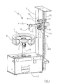
- Figure 1 is a perspective view of the tyre removal machine on which the invention is installed.
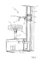
- Figure 2 is a second perspective view of the tyre removal machine on which the invention is installed.
- Figure 3 is a partly sectional view of the device of the invention in a first operative position.
- Figure 4 is a partly sectional view of the device of the invention in a second operative position.
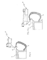
- Figures from 5 to 10 are schematic views of the invention during the demounting of the tyre from the wheel rim.
- Figure 11 is a partly sectional view of a variant of the invention in a first operative position.
- FIGS. 1 and 6 show the tyre removal machine 1 comprising a lower casing 2, from which there upperly emerges a rotary shaft 3 for supporting the support and locking means 4 for the wheel rim 5 on which the tyre 6 is installed.
- the shaft 3, and hence the support and locking means 4 for the wheel rim 5, can translate axially, being operated by suitable operating means positioned within the casing 2.
- a vertical frame 7 provided with slide guides 70 for a carriage 8 arranged to support the device 9 of the invention.
- the carriage 8 can translate vertically by virtue of a known male-female screw mechanism 300, being provided with wheels 81 travelling along guides 70 on the frame 7.
- the device 9 comprises a tool 15 for automatically demounting the tyre 6 from the wheel rim 5.
- the device 9 comprises means 100 for positioning the tool 15 in a first tyre bead seeking and gripping position in which the tool 15 is orientated towards the centre of the wheel rim, and means 200 enabling the tool 15 to be positioned in a second position for extracting said tyre bead from the wheel rim 5, in which the tool 15 is perpendicular to the axis of the device 9 or is orientated towards the frame 7.
- Said tool operating means 200 comprise a first cylinder-piston unit 10 composed of a cylinder 11 within which there slides a piston 12, the piston rod 13 of which emerges from the interior of the cylinder and is fixed to a bar 14 which slides within a prolongation 110 of the cylinder.
- the tyre demounting tool 15 is hinged to the free end of the bar 14. Said tool 15 is substantially of hook shape and upperly presents two lugs 150 between which said tool operating means 100 are connected.
- Said operating means 100 comprise a second cylinder-piston unit 16 composed of a cylinder 17 externally hinged to said lugs and containing a sliding piston 18, the piston rod 19 of which emerges from the cylinder 17.
- the free end of the piston rod 19 is fixed to the end of a profiled plate 20 which slides on the upper surface of the prolongation 110 of the cylinder 11.
- each of the levers 21 is pivoted at its centre to a pin 111 on the bar 14, which emerges from a respective slot 112 on the prolongation 110.
- the two levers or arms 21 enable the tool 15 to be positioned in said second extraction position shown in Figure 10.
- the operation of the invention can be controlled by the operator via suitable control means, not shown, positioned on the casing 2 of the tyre removal machine, or can be controlled automatically by a processor.
- the operator After releasing the tyre bead and locking the wheel in position, the operator adjusts the position of the shaft 3 relative to the frame 7 on the basis of the wheel diameter. At this point the operator operates the device 9 to move it into the position shown in Figure 5, i.e. he positions the demounting tool 15 in proximity to the wheel rim edge, at a few millimetres therefrom.
- the device 9 When in this position the device 9 is lowered by a predetermined amount as shown in Figure 6, and its hook-shaped lower end is inserted between the bead retaining flange on the wheel rim and the sidewall of the tyre.
- the tool When in position, the tool is brought into the bead seeking and gripping position ( Figure 7) by rotating it about the vertical axis through a predetermined angle in the direction of the wheel rim axis, so that the hook-shaped end of the tool 15 grips the edge of the tyre bead.
- the tool is then brought into the first extraction position coinciding with the (vertical) rest position. From this position the device 9 is raised, as shown in Figure 9, in order to extract a portion of the upper tyre bead to above the wheel rim.
- the tool When the upper tyre bead has been extracted, the tool is positioned in the seeking position to release the tool from it, after which the tool is returned to its rest position.
- the tool 15 can be positioned in said second extraction position ( Figure 10) by the action of the cylinder-piston unit 10, as soon as the tyre upper bead has been gripped in the described manner and a part thereof extracted from the wheel rim edge.
- Operating the cylinder-piston unit 10 causes the bar 14 to translate axially, and with it the profiled plate 20 which, because of the mechanism by which it is secured to the bar 14, advances by a greater amount than the bar to cause the tool to rotate into said second extraction position.
- Figure 11 shows a simplified variant of the invention, which is suitable for use, for example, in demounting large diameter tyres.
- the automatic tyre demounting device 24 of this simplified variant differs from the preceding in that the position for seeking and gripping the tyre bead requires the tool to be maintained perpendicular to the axis, rather than orientated towards the centre of the wheel rim as in the preceding embodiment.
- the tool 15 is connected to the lever 21 by a connecting rod 25.
Landscapes
- Engineering & Computer Science (AREA)
- Mechanical Engineering (AREA)
- Tires In General (AREA)
- Testing Of Balance (AREA)
- Moulds For Moulding Plastics Or The Like (AREA)
Claims (10)
- Automatische Vorrichtung (9;24) zur Demontage eines Reifens (6) von einer Radfelge (5), die einen Rahmen (7), Dreh- und Trägereinrichtungen (3,4) zum Drehen und Tragen der Radfelge (5) und des Reifens (6), wobei die Einrichtungen (3,4) mit dem Rahmen (7) verbunden sind, und ein mit einer ersten Positionierungs-/Betätigungseinrichtung (100) betriebsmäßig verbundenes Demontagewerkzeug (15) zur Positionierung des Werkzeuges (15) in einer Such- und ersten Greifposition, in der sich das Werkzeug (15) senkrecht zu der Achse der Vorrichtung (9;24) befindet oder in eine erste Richtung in Richtung des Mittelpunktes der Radfelge (5) gedreht wird, um einen Reifenwulst zu ergreifen, und eine zweite Positionierungs-/Betätigungseinrichtung (200) zur Betätigung des Werkzeuges (15) zur Extraktion des Reifenwulstes von der Radfelge (5) aufweist, wobei das Werkzeug (15) parallel zu der Achse positioniert, oder in einer zu der ersten Richtung entgegengesetzten Richtung gedreht wird,
dadurch gekennzeichnet, dass
sie eine Stange (14) aufweist, an deren Ende das Werkzeug (15) in einer Zwischenposition gelenkig angebracht ist, wobei die erste Positionierungs-/Betätigungseinrichtung (100) weiterhin eine Verbindungsstange (18,19,20;25) aufweist, wobei ein entgegengesetztes Ende der Verbindungsstange (18,19,20;25) mit der Stange (14) über eine Hebelverbindung (21) verbunden ist, und wobei die zweite Positionierungs-/Betätigungseinrichtung (200) weiterhin eine Vorschub- und Rückzugseinrichtung (10) aufweist, und wobei die Stange (14) weiterhin an der Vorschub- und Rückzugseinrichtung (10) befestigt ist. - Vorrichtung nach Anspruch 1,
dadurch gekennzeichnet, dass
die Verbindungsstange (18,19,20) eine veränderbare Länge aufweist. - Vorrichtung nach Anspruch 2,
dadurch gekennzeichnet, dass
die Verbindungsstange (18,19,20) veränderbarer Länge das Werkzeug (15) in die Lage versetzt, in der Suchposition positioniert zu werden, in der es in Richtung des Radfelgenmittelpunktes ausgerichtet ist. - Vorrichtung nach Anspruch 2 oder 3,
dadurch gekennzeichnet, dass
die Verbindungsstange veränderbarer Länge eine Zylinder-Kolbeneinheit (16) aufweist. - Vorrichtung nach Anspruch 1,
dadurch gekennzeichnet, dass
die Einrichtungen zum Vorschub und Rückzug der Stange (14) eine Zylinder-Kolbeneinheit (10) aufweisen. - Vorrichtung nach Anspruch 5,
dadurch gekennzeichnet , dass
die Stange (14) innerhalb einer Verlängerung (110) des Zylinders der Zylinder-Kolbeneinheit (10) gleitet, wobei der Stab der Einheit (10) mittels eines Paares von Hebeln (21) gelenkig an der Stange (14) angebracht ist, die an ihrem entgegengesetzten Ende über einen Schlitz (210) gelenkig an einem von der Verlängerung (110) des Zylinders (11) abzweigenden Ansatz (22) angebracht sind. - Vorrichtung nach Anspruch 1,
dadurch gekennzeichnet, dass
die Vorschub- und Rückzugseinrichtungen (10) mit einem sich in Form einer Translation vertikal auf dem Rahmen (7) bewegenden Trägerschlitten (8) verbunden sind. - Vorrichtung nach Anspruch 7,
dadurch gekennzeichnet, dass
der Trägerschlitten (8) durch ein Schraubenspindel-Schraubenmuttersystem (300) in Form einer Translation angetrieben wird. - Vorrichtung nach Anspruch 1,
dadurch gekennzeichnet, dass
das Demontagewerkzeug (15) einen hakenförmigen Abschnitt zum Ergreifen des Wulstes des Reifens (6) aufweist. - Reifendemontagemaschine,
dadurch gekennzeichnet, dass
sie eine Vorrichtung (9;24) nach einem der vorangegangenen Ansprüche aufweist.
Applications Claiming Priority (2)
| Application Number | Priority Date | Filing Date | Title |
|---|---|---|---|
| ITRE20020068 | 2002-09-13 | ||
| IT000068A ITRE20020068A1 (it) | 2002-09-13 | 2002-09-13 | Dispositivo automatico semplificato per lo smontaggio |
Publications (2)
| Publication Number | Publication Date |
|---|---|
| EP1398184A1 EP1398184A1 (de) | 2004-03-17 |
| EP1398184B1 true EP1398184B1 (de) | 2007-10-17 |
Family
ID=11454265
Family Applications (1)
| Application Number | Title | Priority Date | Filing Date |
|---|---|---|---|
| EP03077447A Expired - Lifetime EP1398184B1 (de) | 2002-09-13 | 2003-08-05 | Automatische Reifendemontiervorrichtung, und Reifendemontiergerät mit einer solchen Vorrichtung |
Country Status (6)
| Country | Link |
|---|---|
| US (1) | US6880605B2 (de) |
| EP (1) | EP1398184B1 (de) |
| JP (1) | JP2004106831A (de) |
| DE (1) | DE60316892T2 (de) |
| ES (1) | ES2294240T3 (de) |
| IT (1) | ITRE20020068A1 (de) |
Cited By (2)
| Publication number | Priority date | Publication date | Assignee | Title |
|---|---|---|---|---|
| EP2987661A1 (de) | 2014-07-28 | 2016-02-24 | Butler Engineering & Marketing S.p.A. | Vorrichtung zur montage- und demontage eines bereiften rades sowie maschine mit solch einer vorrichtung |
| EP3315332A1 (de) | 2016-10-18 | 2018-05-02 | NEXION S.p.A. | Reifenwechselmaschine |
Families Citing this family (31)
| Publication number | Priority date | Publication date | Assignee | Title |
|---|---|---|---|---|
| ITMO20030132A1 (it) * | 2003-05-09 | 2004-11-10 | Giuliano Srl | Macchina per il montaggio e lo smontaggio di pneumatici e cerchi di ruote per veicoli. |
| ITRE20040049A1 (it) * | 2004-05-06 | 2004-08-06 | Corghi Spa | Dispositivo automatico per lo smontaggio ed il montaggio dei pneumatici |
| ITVR20050037A1 (it) * | 2005-03-23 | 2006-09-24 | Butler Eng & Marketing | Utensile per il montaggio/smontaggio automatico di un pneumatico su/da un cerchione |
| ITRE20050079A1 (it) * | 2005-07-11 | 2007-01-12 | Corghi Spa | Metodo e dispositivo per lo smontaggio di pneumatici autoportanti |
| US7343955B2 (en) | 2005-12-28 | 2008-03-18 | Hennessy Industries, Inc. | Tire changing machine |
| US7438109B2 (en) * | 2005-12-30 | 2008-10-21 | Hennessy Industries, Inc. | Tire changer |
| ITTO20060285A1 (it) * | 2006-04-14 | 2007-10-15 | Bridgestone Corp | Macchina per l'assemblaggio e disassemblaggio di uno pneumatico provvisto di un anello rigido interno anti-appiattimento |
| ITMO20070350A1 (it) | 2007-11-21 | 2009-05-22 | Giuliano Spa | Macchina per il montaggio e lo smontaggio di pneumatici di ruote per veicoli |
| JP2009227006A (ja) * | 2008-03-19 | 2009-10-08 | Onodani Kiko Kk | タイヤ着脱装置のタイヤビード案内装置 |
| ITVR20080050A1 (it) * | 2008-04-28 | 2009-10-29 | Butler Eng & Marketing | Gruppo stallonatore per una macchina monta-smontagomme |
| IT1392089B1 (it) * | 2008-10-13 | 2012-02-09 | Giuliano S P A Ora Giuliano Group S P A | Testa operativa per lo smontaggio ed il montaggio di pneumatici di ruote per veicoli |
| WO2010089070A1 (de) * | 2009-02-04 | 2010-08-12 | Josef Dagn | Vorrichtung zum trennen eines autoreifens von der felge |
| JP5026477B2 (ja) * | 2009-07-30 | 2012-09-12 | 小野谷機工株式会社 | タイヤ上ビードの取外し方法及びその装置 |
| JP5026473B2 (ja) * | 2009-06-30 | 2012-09-12 | 小野谷機工株式会社 | タイヤ上ビードの取外し方法 |
| ITMI20111968A1 (it) * | 2011-10-28 | 2013-04-29 | Roberto Santachiara | Macchina smontagomme |
| ITBO20120189A1 (it) | 2012-04-11 | 2013-10-12 | Corghi Spa | Utensile di smontaggio per una macchina smontagomme e macchina smontagomme |
| ITVR20120159A1 (it) * | 2012-08-01 | 2014-02-02 | Butler Engineering And Marketing S P A | Dispositivo di smontaggio di un pneumatico da un cerchione e metodo di smontaggio di una ruota gommata |
| EP2988957B1 (de) * | 2013-04-26 | 2017-06-07 | Devel S.r.l. | Reifenwechselmaschine |
| EP3501862B1 (de) | 2014-05-30 | 2022-08-03 | Snap-on Equipment Srl a unico socio | Verfahren zur montage und demontage eines reifens auf und von einer radfelge |
| EP2949488B1 (de) * | 2014-05-30 | 2019-05-15 | Snap-on Equipment Srl a unico socio | Montage-/Demontagewerkzeugeinheit mit vorgespanntem Werkzeug |
| US11001108B2 (en) * | 2014-05-30 | 2021-05-11 | Snap-On Equipment Srl A Unico Socio | Mounting/demounting tool unit with preloaded tool |
| ES2616537T3 (es) * | 2014-07-03 | 2017-06-13 | Corghi S.P.A. | Máquina y método para montar y desmontar un neumático |
| DE202014008932U1 (de) | 2014-11-11 | 2016-03-02 | Snap-On Equipment Srl A Unico Socio | Reifenmontage- und -demontagewerkzeug |
| CN104442238B (zh) * | 2014-11-28 | 2016-08-31 | 刘高生 | 一种轮胎拆装机 |
| CN105459743A (zh) * | 2015-12-25 | 2016-04-06 | 镇江奥兰迪汽车部件有限公司 | 一种轮毂装胎工具 |
| CN108528153B (zh) * | 2017-03-06 | 2020-07-21 | 科维(营口)工业有限公司 | 一种拆胎装置及轮胎拆装机 |
| CN107856482B (zh) * | 2017-11-16 | 2023-06-06 | 营口大力汽保设备科技有限公司 | 一种拆胎机 |
| CN110422019A (zh) * | 2019-07-19 | 2019-11-08 | 广东雅迪机车有限公司 | 一种扒胎机用鸟头和扒胎机 |
| CN110774840B (zh) | 2019-11-29 | 2024-07-16 | 营口大力汽保设备科技有限公司 | 一种轮胎拆装机 |
| IT202100001235A1 (it) | 2021-01-25 | 2022-07-25 | Snap On Equip Srl Unico Socio | Apparato smontagomme con utensile a basculamento automatico |
| IT202100001238A1 (it) | 2021-01-25 | 2022-07-25 | Snap On Equip Srl Unico Socio | Apparato smontagomme |
Family Cites Families (6)
| Publication number | Priority date | Publication date | Assignee | Title |
|---|---|---|---|---|
| CH399214A (fr) * | 1963-10-15 | 1966-03-31 | Furrer Ferdinand | Appareil pour déjanter les pneumatiques de roues de véhicules |
| US3511296A (en) * | 1968-04-29 | 1970-05-12 | Big Four Automotive Equipment | Tire changer having friction lock |
| US5226465A (en) * | 1991-02-19 | 1993-07-13 | Stahlgruber Otto Gruber Gmbh & Co. | Mounting device for motor vehicle tires |
| IT1310590B1 (it) * | 1999-05-14 | 2002-02-19 | Giuliano Srl | Stazione multifunzionale per il montaggio e lo smontaggio dipneumatici sia di tipo convenzionale sia speciale. |
| IT1319475B1 (it) | 2000-08-03 | 2003-10-10 | Corghi Spa | Dispositivo automatico per lo smontaggio ed il montaggio deipneumatici, e macchine smontagomme cosi' attrezzate |
| JP3626088B2 (ja) * | 2000-11-09 | 2005-03-02 | 小野谷機工株式会社 | 自動車タイヤ取外し方法、およびタイヤ取外し装置 |
-
2002
- 2002-09-13 IT IT000068A patent/ITRE20020068A1/it unknown
-
2003
- 2003-08-04 US US10/632,910 patent/US6880605B2/en not_active Expired - Lifetime
- 2003-08-05 DE DE60316892T patent/DE60316892T2/de not_active Expired - Lifetime
- 2003-08-05 ES ES03077447T patent/ES2294240T3/es not_active Expired - Lifetime
- 2003-08-05 EP EP03077447A patent/EP1398184B1/de not_active Expired - Lifetime
- 2003-09-09 JP JP2003317128A patent/JP2004106831A/ja active Pending
Cited By (6)
| Publication number | Priority date | Publication date | Assignee | Title |
|---|---|---|---|---|
| EP2987661A1 (de) | 2014-07-28 | 2016-02-24 | Butler Engineering & Marketing S.p.A. | Vorrichtung zur montage- und demontage eines bereiften rades sowie maschine mit solch einer vorrichtung |
| EP3315332A1 (de) | 2016-10-18 | 2018-05-02 | NEXION S.p.A. | Reifenwechselmaschine |
| EP3315331A1 (de) | 2016-10-18 | 2018-05-02 | NEXION S.p.A. | Reifenwechselmaschine |
| US10906365B2 (en) | 2016-10-18 | 2021-02-02 | Nexion S.P.A. | Tyre changing machine |
| US11110761B2 (en) | 2016-10-18 | 2021-09-07 | Nexion S.P.A. | Tyre changing machine |
| US11897297B2 (en) | 2016-10-18 | 2024-02-13 | Nexion S.P.A. | Tyre changing machine |
Also Published As
| Publication number | Publication date |
|---|---|
| US20040055712A1 (en) | 2004-03-25 |
| DE60316892D1 (de) | 2007-11-29 |
| US6880605B2 (en) | 2005-04-19 |
| ITRE20020068A0 (it) | 2002-09-13 |
| ITRE20020068A1 (it) | 2004-03-14 |
| JP2004106831A (ja) | 2004-04-08 |
| ES2294240T3 (es) | 2008-04-01 |
| DE60316892T2 (de) | 2008-01-31 |
| EP1398184A1 (de) | 2004-03-17 |
Similar Documents
| Publication | Publication Date | Title |
|---|---|---|
| EP1398184B1 (de) | Automatische Reifendemontiervorrichtung, und Reifendemontiergerät mit einer solchen Vorrichtung | |
| US6619362B2 (en) | Automatic tyre removal and mounting device and tyre removal machines equipped therewith | |
| EP1897708B1 (de) | Maschine zum Anbringen und Abnehmen von Reifen und Felgen für Fahrzeuge | |
| US8905112B2 (en) | Device for demounting the second bead of a tire from a rim and respective demounting method | |
| EP2233325A1 (de) | Maschine zum Anbringen und Abnehmen der Radreifen eines Fahrzeugs | |
| JP2002029231A (ja) | タイヤ取り外し機用の自動ビード解放装置及びそれを具備したタイヤ取り外し機 | |
| EP1459913B1 (de) | Vorrichtung zum Montieren und Demontieren von Reifen | |
| EP2338705B1 (de) | Reifenwulstabdrückvorrichtung für Reifenwechselgeräte | |
| EP2927028B1 (de) | Maschine zur Montage/Demontage eines Reifens | |
| US9944136B2 (en) | Machine for removing and fitting wheel tyres for vehicles | |
| EP4169744B1 (de) | Maschine zur montage und demontage eines reifens in bezug auf eine entsprechende felge und radwartungsverfahren | |
| US8381791B2 (en) | Device for lifting a bottom side wall of a tyre in a tyre removing machine | |
| US7946016B2 (en) | Method and machine for removing a tyre fitted with a rigid inner run-flat ring | |
| EP2756969B1 (de) | Maschine zum Entfernen/ Aufbringen eines Reifens von/ auf eine(r) Felge eines Fahrzeugs | |
| EP2988957B1 (de) | Reifenwechselmaschine | |
| CN104159756A (zh) | 用于轮胎更换机的轮胎胎圈抽出装置 | |
| CN205890424U (zh) | 用于车辆的车轮轮胎的拆卸和装配的机器 |
Legal Events
| Date | Code | Title | Description |
|---|---|---|---|
| PUAI | Public reference made under article 153(3) epc to a published international application that has entered the european phase |
Free format text: ORIGINAL CODE: 0009012 |
|
| AK | Designated contracting states |
Kind code of ref document: A1 Designated state(s): AT BE BG CH CY CZ DE DK EE ES FI FR GB GR HU IE IT LI LU MC NL PT RO SE SI SK TR |
|
| AX | Request for extension of the european patent |
Extension state: AL LT LV MK |
|
| 17P | Request for examination filed |
Effective date: 20040712 |
|
| AKX | Designation fees paid |
Designated state(s): DE ES FR IT |
|
| GRAP | Despatch of communication of intention to grant a patent |
Free format text: ORIGINAL CODE: EPIDOSNIGR1 |
|
| GRAS | Grant fee paid |
Free format text: ORIGINAL CODE: EPIDOSNIGR3 |
|
| GRAA | (expected) grant |
Free format text: ORIGINAL CODE: 0009210 |
|
| AK | Designated contracting states |
Kind code of ref document: B1 Designated state(s): DE ES FR IT |
|
| RIN1 | Information on inventor provided before grant (corrected) |
Inventor name: CORGHI, REMO |
|
| REF | Corresponds to: |
Ref document number: 60316892 Country of ref document: DE Date of ref document: 20071129 Kind code of ref document: P |
|
| ET | Fr: translation filed | ||
| REG | Reference to a national code |
Ref country code: ES Ref legal event code: FG2A Ref document number: 2294240 Country of ref document: ES Kind code of ref document: T3 |
|
| PLBE | No opposition filed within time limit |
Free format text: ORIGINAL CODE: 0009261 |
|
| STAA | Information on the status of an ep patent application or granted ep patent |
Free format text: STATUS: NO OPPOSITION FILED WITHIN TIME LIMIT |
|
| 26N | No opposition filed |
Effective date: 20080718 |
|
| REG | Reference to a national code |
Ref country code: FR Ref legal event code: PLFP Year of fee payment: 14 |
|
| REG | Reference to a national code |
Ref country code: FR Ref legal event code: PLFP Year of fee payment: 15 |
|
| REG | Reference to a national code |
Ref country code: DE Ref legal event code: R082 Ref document number: 60316892 Country of ref document: DE Representative=s name: LORENZ & KOLLEGEN PATENTANWAELTE PARTNERSCHAFT, DE Ref country code: DE Ref legal event code: R081 Ref document number: 60316892 Country of ref document: DE Owner name: NEXION S.P.A., IT Free format text: FORMER OWNER: CORGHI S.P.A., CORREGGIO, REGGIO EMILIA, IT |
|
| REG | Reference to a national code |
Ref country code: ES Ref legal event code: PC2A Effective date: 20180529 Ref country code: ES Ref legal event code: PC2A Owner name: NEXION S.P.A. Effective date: 20180529 |
|
| REG | Reference to a national code |
Ref country code: FR Ref legal event code: CD Owner name: NEXION S.P.A., IT Effective date: 20180620 |
|
| REG | Reference to a national code |
Ref country code: FR Ref legal event code: PLFP Year of fee payment: 16 |
|
| PGFP | Annual fee paid to national office [announced via postgrant information from national office to epo] |
Ref country code: IT Payment date: 20220811 Year of fee payment: 20 Ref country code: ES Payment date: 20220908 Year of fee payment: 20 Ref country code: DE Payment date: 20220826 Year of fee payment: 20 |
|
| PGFP | Annual fee paid to national office [announced via postgrant information from national office to epo] |
Ref country code: FR Payment date: 20220824 Year of fee payment: 20 |
|
| P01 | Opt-out of the competence of the unified patent court (upc) registered |
Effective date: 20230530 |
|
| REG | Reference to a national code |
Ref country code: DE Ref legal event code: R071 Ref document number: 60316892 Country of ref document: DE |
|
| REG | Reference to a national code |
Ref country code: ES Ref legal event code: FD2A Effective date: 20230825 |
|
| PG25 | Lapsed in a contracting state [announced via postgrant information from national office to epo] |
Ref country code: ES Free format text: LAPSE BECAUSE OF EXPIRATION OF PROTECTION Effective date: 20230806 |