EP2988957B1 - Reifenwechselmaschine - Google Patents
Reifenwechselmaschine Download PDFInfo
- Publication number
- EP2988957B1 EP2988957B1 EP13730929.0A EP13730929A EP2988957B1 EP 2988957 B1 EP2988957 B1 EP 2988957B1 EP 13730929 A EP13730929 A EP 13730929A EP 2988957 B1 EP2988957 B1 EP 2988957B1
- Authority
- EP
- European Patent Office
- Prior art keywords
- tool
- wheel
- machine
- tyre
- rim
- Prior art date
- Legal status (The legal status is an assumption and is not a legal conclusion. Google has not performed a legal analysis and makes no representation as to the accuracy of the status listed.)
- Active
Links
Images


Classifications
-
- B—PERFORMING OPERATIONS; TRANSPORTING
- B60—VEHICLES IN GENERAL
- B60C—VEHICLE TYRES; TYRE INFLATION; TYRE CHANGING; CONNECTING VALVES TO INFLATABLE ELASTIC BODIES IN GENERAL; DEVICES OR ARRANGEMENTS RELATED TO TYRES
- B60C25/00—Apparatus or tools adapted for mounting, removing or inspecting tyres
- B60C25/01—Apparatus or tools adapted for mounting, removing or inspecting tyres for removing tyres from or mounting tyres on wheels
- B60C25/05—Machines
- B60C25/0527—Adapting to different wheel diameters, i.e. distance between support and tool
-
- B—PERFORMING OPERATIONS; TRANSPORTING
- B60—VEHICLES IN GENERAL
- B60C—VEHICLE TYRES; TYRE INFLATION; TYRE CHANGING; CONNECTING VALVES TO INFLATABLE ELASTIC BODIES IN GENERAL; DEVICES OR ARRANGEMENTS RELATED TO TYRES
- B60C25/00—Apparatus or tools adapted for mounting, removing or inspecting tyres
- B60C25/01—Apparatus or tools adapted for mounting, removing or inspecting tyres for removing tyres from or mounting tyres on wheels
- B60C25/05—Machines
- B60C25/0563—Tools interacting with the tyre and moved in relation to the tyre during operation
- B60C25/0578—Tools interacting with the tyre and moved in relation to the tyre during operation hooking only
-
- B—PERFORMING OPERATIONS; TRANSPORTING
- B60—VEHICLES IN GENERAL
- B60C—VEHICLE TYRES; TYRE INFLATION; TYRE CHANGING; CONNECTING VALVES TO INFLATABLE ELASTIC BODIES IN GENERAL; DEVICES OR ARRANGEMENTS RELATED TO TYRES
- B60C25/00—Apparatus or tools adapted for mounting, removing or inspecting tyres
- B60C25/01—Apparatus or tools adapted for mounting, removing or inspecting tyres for removing tyres from or mounting tyres on wheels
- B60C25/05—Machines
- B60C25/0563—Tools interacting with the tyre and moved in relation to the tyre during operation
- B60C25/0593—Multi-functional tools for performing at least two operations, e.g. bead breaking and bead seeking
Definitions
- the present invention relates to a machine for the fitting and removal of tyres of vehicle wheels.
- the present invention relates to a tyre-changing machine.
- the upper bead (also called “first bead”, or more generically “bead”) of the tyre must first of all be detached from the edge of the rim on which it is fitted (operation also called “bead breaking"). Subsequently, the first bead is hooked and removed from the edge of the rim (bead hook). Finally, the tyre is removed from the rim by pushing it on the opposite side to the first removed bead. To be able to fully remove the tyre from the wheel rim, bead breaking must also be performed for the lower bead (also called “second bead”) of the same tyre.
- tyre-changing machines suitable for both allowing the removal of the tyre from the rim and for allowing the subsequent phase of tyre fitting on the rim.
- Tyre-changing machines generally comprise a base frame, which supports a rotating rim clamping device, which allows starting the rotation of the wheel around a work axis.
- the base frame is also associated an arm orthogonal to the work axis, on which are generally fitted a bead pushing tool and a bead hooking tool.
- the arm and/or the rotating clamping device are motor-driven so they can be moved closer to one another.
- the tyre bead is initially removed by means of the pushing tool or other equipment with which tyre-changing machines are provided. Afterwards, the hooking tool is inserted between the bead and the edge of the rim to grip the edge of the bead, and is then moved away from the rim, so as to remove the bead.
- the tyre bead undergoes heavy stress and the tyre is deformed in a more or less elastic way.
- some tyre-changing machines have a hooking tool fitted on the relative arm in a rotatable way around an axis orthogonal to the rotation axis of the wheel.
- the hooking tool is arranged with its rotation axis tangent to the wheel rim and, during rotation, it always remains very close to such edge. Consequently, the edge of the bead does not move far away from the rim and does not undergo particularly heavy stresses.
- a machine for fitting and removing the tyres of vehicle wheels, comprising a supporting frame for a rotating clamping device suitable for supporting a vehicle wheel and making it rotate around a work axis, a tyre hooking tool which is associable with the frame and has an elongated portion insertable longitudinally between the tyre bead and the wheel rim for the extraction of the bead, and first and second sliding means associable with the frame and suitable for moving the rotating clamping device and the hooking tool, respectively, along a first parallel direction and a second direction orthogonal to the portion of tool.
- the machine also comprises tilting means of the rotating clamping device around a tilting axis orthogonal to such first and second direction.
- the tyre-changing machine described in such patent is more practical to use than the previously known prior-art machines, but nevertheless still has hooking tool positioning which is not perfect with respect to the tyre when the hooking tool itself is inserted between the tyre bead and the edge of the rim to grip the bead and then remove it from the wheel rim.
- the applicant has faced the problem of providing a tyre-changing machine which is easy and practical to use for fitting and removing the tyres of vehicle wheels, making it possible to considerably reduce fitting/removal times, with a consequent reduction in working, labour and maintenance costs.
- the present invention provides a tyre-changing machine like that indicated in claim 1.
- a machine for fitting and removing vehicle wheel tyres comprising at least a supporting frame for at least a rotating clamping device suitable for supporting at least a vehicle wheel and making this rotate around a work axis, at least a tyre hooking tool which is associable with the frame and has a substantially elongated portion insertable between the tyre bead and the wheel rim for the extraction of the bead, first sliding means associable with the frame and suitable for moving at least said hooking tool along a first direction substantially parallel to said tool portion, second sliding means associable with the frame and suitable for moving at least said rotating clamping device along a second direction substantially orthogonal to said tool portion, and furthermore tilting means of said rotating clamping device, characterised in fact that said tilting means are suitable for rotating around a tilting axis parallel to said second direction, is able to facilitate the insertion of the hooking tool between the bead and the edge of the rim to grip the edge
- the wheel can be momentarily blocked, following said swinging, in an oblique position perfect for allowing said hooking tool to be easily inserted tangentially in the inner channel of the rim between the bead and the edge of the wheel rim.
- said small wheel rotation allows the hooking tool to move, above the rim, a larger portion of the bead, compared to the case wherein the wheel is arranged in horizontal position. This way, the detachment of the tyre bead from the wheel rim is made easier and faster.
- the hooking device manages to insert itself suitably inside the internal rim channel, without having to be pressed at length against the tyre before finding a suitable hooking point between the tyre and the rim.
- the tyre-changing machine of the present invention has the further advantage of preventing the hooking tool from damaging the tyre following difficulty in inserting the hooking tool itself between the bead and the edge of the rim, consequently also facilitating the daily job of the operator of said machine.
- the tyre-changing machine of the present invention also has the further advantage of performing vehicle wheel tyre removal operations more quickly than prior-art devices.
- levers do not have to be used to further lift the bead, and consequently, there is no risk of the tyre being cut by the sharp parts of such levers.
- said tilting means are suitable for rotating around said tilting axis so the wheel is able to reach an angle between 0° and 45°, a preferred angle being between 5° and 25°, more preferably between 10° and 20° with respect to the tilting axis.
- said frame of the machine of the present invention comprises a support base on the ground that supports said rotating clamping device.
- the machine of the present invention comprises a vertical supporting column (hereinafter also called "first column") for said hooking tool which is associated with said base.
- said hooking tool is fitted on an arm (hereinafter also called “first arm”) associable with said supporting column, in a substantially horizontal position. More preferably, said hooking tool is arranged substantially in vertical position, along the longitudinal direction of the column.
- said tilting means are suitable for rotating around a tilting axis parallel to said second direction, the distance remains constant between said column and the wheel positioned on said rotating clamping device, for the entire duration of swinging.
- the prior-art patent mentioned above because the swinging occurred around a tilting axis orthogonal to said second direction, during swinging, the upper edge of the wheel tilted towards the column until it touched the column itself, thus preventing perfect swinging.
- the advantage is obtained that, once the distance has been adjusted between the clamping device and the column, this remains constant and such distance can therefore be adjusted so as to be able to also use the machine of the present invention to remove/fit tyres of special dimensions, because the wheel can be moved closer to the column than was possible in the above-mentioned prior-art document, without running the risk, during swinging, of the wheel knocking against said column and therefore also against said hooking device positioned on the column itself. In practice, during swinging, the wheel fails to encounter any obstacle, thus permitting the achievement of the desired tilt angle for better operation.
- said hooking tool is rigidly associated with said substantially horizontal arm associable with said column.
- said hooking tool is supported by a tool holding device, said tool holding device being associated with said arm, in correspondence to the extremity of the arm on the opposite side of said column, and being able to rotate around a rotation line along said arm.
- said tool holding device is able to not only support said hooking tool but also other tools useful for the tyre fitting/removal operations, such as, e.g., a blade or a pushing tool.
- a blade or a pushing tool The purpose of said blade is to penetrate between the bead and the rim.
- Said pushing tool preferably with a substantially truncated-cone shape, can instead be used to make it easier to detach the tyre from the wheel rim; in fact, especially in the cases of the wheel not having been handled for a long period of time, the tyre tends to fasten itself onto the wheel rim to an increasing extent, creating a strong adhesion force between tyre and rim, and thus making its detachment difficult when necessary.
- said tool holding device is able to support a first tool, such as, e.g., said hooking tool, and a second tool, such as, e.g., said pressure device or said blade, positioned in correspondence to the two opposite extremities of said tool holding device.
- a first tool such as, e.g., said hooking tool
- a second tool such as, e.g., said pressure device or said blade
- said tool holding device is able to support a first tool, such as, e.g., said hooking tool, a second tool, such as, e.g., said pressure device, and a third tool, such as, e.g., said blade, said first, second and third tool being positioned in a way substantially radically equidistant, at about 120° the one from the other.
- a first tool such as, e.g., said hooking tool
- a second tool such as, e.g., said pressure device
- a third tool such as, e.g., said blade
- said vertical supporting column of the machine of the present invention also comprises a second arm arranged in a position substantially horizontal to the first arm described above; more preferably, said second arm is placed at a level of the column which is lower than said first arm.
- said second arm also has, at its extremity on the opposite side of the column, a rotatable tool holding device able to support tools useful in the tyre removal/fitting phase. This way, e.g., a blade supported by the tool holding device present on the second arm can be used to more easily free the second bead from the wheel rim once the first bead has already been freed.
- the machine of the present invention also comprises a second column; preferably, said second column is arranged vertically on said base for resting on the ground, in correspondence to a side of the base adjacent to that in correspondence to which said above-described first column is arranged.
- said second column is associated at least one arm, preferably at least two arms, sliding along the vertical axis of said second column, at the free extremity of each of said at least one arm being applied a roller, preferably with frustoconical shape, having a central cavity.
- the height of said at least one arm of the second column can be regulated to bring the corresponding roller in correspondence to the tyre when it is still well fastened to the wheel rim.
- the shape of said roller is such as to adapt to the shape of the tyre and therefore, by applying a pressure downwards, the tyre can be detached from the rim.
- said second column has at least two arms, arranged in symmetric position with respect to the vertical axis of said second column, so the corresponding rollers associated with them apply a pressure on the tyre in two substantially diametrically opposite areas to make the detachment of the tyre from the rim easier, winning particularly consistent resistances by the tyre to detach from the wheel rim.
- said tilting means comprise a reduction gear tube integral with a self-centering plate suitable for sustaining said rotating clamping device, said self-centering plate having a pin around which the reduction gear tube swings along said swinging axis parallel to said second direction.
- said reduction gear tube is integral with a reduction unit having a reduction gear head.
- said reduction gear is operated by a cylinder.
- said self-centering plate is sustained by two supporting uprights fastened to the plane of said slide.
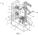
- the machine 1 comprises a frame 2 which supports at least one rotating clamping device 3 suitable for sustaining a wheel R of vehicles and causing such wheel R to rotate around a work axis A.
- the frame 2 comprises a base 6 for resting on the ground, which supports the rotating clamping device 3 so the latter is turned upwards.
- a first supporting column 7 extends upwards, on the side part of which, turned towards the rotating clamping device 3, is fitted a first arm 8 which extends horizontally with respect to the column 7, towards the rotating clamping device 3 itself.
- a tool holding device 21 At the free extremity of the arm 8, that on the opposite side with respect to the column 7, a tool holding device 21 can be seen which is rotatable around the rotation line Y along the arm 8.
- the tool holding device 21, as shown in the Figure 1 supports, in correspondence to its lower extremity, a pushing tool 9 and, in correspondence to its upper extremity, a hooking tool 4.
- the pushing tool 9 is in use position towards the wheel R and can be used to push the tyre downwards and thus make its detachment from the rim of the wheel R easier. It is easy to appreciate however that, by making the tool holding device 21 rotate by 180° around the rotation line Y, the hooking tool 4 and the pushing tool 9 end up in an inverted position with respect to that shown in Figure 1 , so that, this time, it is the hooking tool 4 which is in the use position to carry out the first bead breaking operation.
- the hooking tool 4 is arranged in a substantially vertical way downwards, parallel to the erect longitudinal side of the supporting column 7, and having an elongated portion 5, suitable for being inserted tangentially between the first bead of the tyre and the rim of the wheel R, for the extraction of the first bead.
- the Figure 1 also shows a second arm 8' arranged in a substantially horizontal position, at a lower level of the column 7 with respect to the first arm 8.
- the second arm 8' also has, at its extremity on the opposite side of the supporting column 7, a tool holding device 21' which is rotatable around the rotation line Y' along the second arm 8' and which is able to support, in correspondence to its lower and upper extremities, a pushing tool 9' and a hooking tool 4', the positions of which can be exchanged following a 180° rotation of the tool holding device 21'.
- the hooking tool 4' associated with the lower second arm 8' can be used to more easily free the second bead from the rim of the wheel, once the first bead has already been freed.
- the Figure 1 also shows a second supporting column 22 arranged vertically on the base 6 for resting on the ground, in correspondence to a side of the base 6 adjacent to that in correspondence to which the first column 7 described above is arranged.
- the second column 22 With the second column 22 are associated two arms 23, 24 sliding along the vertical axis of the second column 22, arranged in symmetric position with respect to the vertical axis of the second column 22.
- rollers 25, 26 can be used to push the tyre downwards and thus make its detachment from the rim of the wheel R easier.
- first sliding means S suitable for moving the first arm 8 and the second arm 8' (and with these the corresponding tool holders 21 and 21' and the hooking tools supported by them) along a first direction D along the vertical direction of the first column 7.
- such sliding means S and S' in practice, consist of movement means for moving the arms along the respective columns and comprise, e.g., hydraulic jacks (not shown), fitted vertically inside the columns 7 and 22 and positioned between the frame 2 and the arms.
- the second sliding means 10 suitable for moving the rotating clamping device 3 along a second direction E orthogonal to the first direction D, i.e., along a horizontal direction with respect to the first column 7.
- the second sliding means 10 comprise rectilinear guide means along which is fitted a slide 11, fitted on a frame 2, which supports the rotating clamping device 3.
- the second sliding means 10 also have second hydraulic jacks (not shown in the illustration) having one extremity associated integral with the frame 2 and the opposite extremity which assures instead on one of the sleeves of the slide 11.
- the second hydraulic jacks are in practice filled and emptied of fluid under pressure to move the rotating clamping device 3 towards the column 7 along the direction E.
- tilting means 20 which allow the rotating clamping device 3 to swing around the tilting axis B parallel to the second direction E.
- the tilting means 20 are made up of a reduction gear 12 operated by a cylinder 13, wherein the reduction gear 12, positioned underneath the slide 11, has a head 14 inserted in and integral with a reduction gear tube 15, which protrudes beyond the plane of the slide 11.
- the respective bases of two fixed vertical supporting uprights 16, 17 which support, in correspondence to their extremities opposite those of their bases, a self-centering plate 18, integral with the movement of the reduction gear tube 15.
- the two supporting uprights 16, 17 are fastened so their bases are in symmetric position with respect to the reduction gear tube 15.
- a pin 19 is provided around which swings the reduction gear tube 15, along the tilting axis B parallel to the direction E towards the first supporting column 7. Consequently, by operating the cylinder 13 by means of a motor, the reduction gear 12, its head 14, the reduction gear tube 15 and the self-centering plate 18, on which is fitted the clamping device 3 for the wheel R, are made to move by swinging around the pin 19. This way, the swinging is achieved of the wheel R around the tilting axis B parallel to the direction E towards the column 7.
- a wheel R of a vehicle made up of a rim around which a tyre is present, is placed on the clamping device 3 to be able to extract the tyre from the rim.
- a choice can be made whether to submit the tyre to the pressure applied by the pair of rollers 25, 26 associated with the arms 23, 24 of the second column 22 (in case a strong pressure has to be applied on two diametrically opposite areas of the tyre) or to the pushing device 9 associated with the arm 8 of the first column 7 (in case a lesser pressure is required to be applied on just one area of the tyre).
- the two rollers 25 and 26 or the pushing device 9 apply considerable pressure on the tyre, such as to push it downwards, until it detaches from the rim of the wheel R. Subsequently, the plane of the slide 11, and with it the clamping device 3 and the wheel R fitted on it, is moved closer to the first column 7 by means of first sliding means S along the second direction E, until the wheel R is at a preestablished distance from the first column 7 according to the type and size of the tyre P.
- the cylinder 13 is then operated to cause the reduction gear tube 15 to swing around the tilting axis B parallel to the second direction E towards the first supporting column 7; integral with the reduction gear tube 15, the self-centering plate 18, the clamping device 3 and, consequently, the wheel R also rotate.
- the cylinder 13 is blocked when the wheel R is in oblique position with an angle of around 15° with respect to the horizontal plane.
- the tool holding device 21 is then lowered along the first direction D, i.e., along the vertical direction of the first supporting column 7, until the elongated portion 5 of the hooking tool 4, previously positioned in correspondence to the lower portion of the tool holding device 21 by means of a 180° rotation of the tool holding device 21 itself, comes into contact with the wheel R.
- Such contact between the hooking tool 4 and the wheel R occurs in correspondence to a point of the rim which is the closest possible to the column 7 and which is at a more or less intermediate height of the wheel R between the lowest point and the highest point of the wheel R with respect to the supporting plane of the slide 11.
- the hooking tool 4 has enough room and ease of operation inside the rim and is therefore in such a position that its elongated portion 5 can be easily inserted tangentially in the rim channel between the rim itself and the first bead of the tyre of the wheel R, without having to force in any particular way against the tyre itself.
- the hooking tool 4 lifts up the portion of the first bead in correspondence to the hooking tool above the rim; by then making the wheel R rotate slightly around the work axis A, thanks to the tilted position of the wheel, a major portion of the bead will find itself above the rim and, from here, after a few seconds, the entire first bead of the tyre will be extracted from the rim of the wheel R.
- the rotation R is then blocked around the work axis A, the tyre being pushed from below upwards by means of a roller and then the second bead also being lifted using the hooking tool 4' associated with the second arm 8' to fully extract the tyre from the rim.
- the cylinder 13 is operated so as to return the clamping device 3 to horizontal position and remove the wheel R from the tyre-changing machine 1 of the present invention.
- a tyre-changing machine can be made wherein two distinct clamping devices 3 are present, positioned symmetrically with respect to the first supporting column 7, suitable for accommodating on them two wheels R, one for each clamping device 3, to be able to act separately and at the same time on the two wheels R with the same tyre-changing machine.
Landscapes
- Engineering & Computer Science (AREA)
- Mechanical Engineering (AREA)
- Testing Of Balance (AREA)
- Vehicle Cleaning, Maintenance, Repair, Refitting, And Outriggers (AREA)
Claims (13)
- Maschine (1) zum Anbringen und Entfernen von Reifen von Fahrzeugrädern (R), dadurch gekennzeichnet, dass die Maschine (1) Folgendes umfasst:- mindestens einen Stützrahmen (2) für mindestens eine sich drehende Klemmeinrichtung (3), geeignet zum Tragen wenigstens eines Rades (R) von Fahrzeugen und Bringen desselben in Drehung um eine Arbeitsachse (A),- mindestens ein Einhakwerkzeug (4) zum Einhaken des Reifens, das mit dem Rahmen (2) assoziierbar ist und mit einem länglichen Abschnitt (5) versehen ist, der zwischen der Reifenwulst des Rades (R) und der Felge des Rades (R) eingefügt werden kann, um die Wulst zu entfernen,- erste Verschiebungsmittel (S), die mit dem Rahmen (2) assoziierbar und dafür geeignet sind, das wenigstens eine Einhakwerkzeug (4) entlang einer ersten Richtung (D) im Wesentlichen parallel zu dem Abschnitt des Werkzeugs (5) zu bewegen,- zweite Verschiebungsmittel (10), die mit dem Rahmen (2) assoziierbar und dafür geeignet sind, die mindestens eine sich drehende Klemmeinrichtung (3) entlang einer zweiten Richtung (E) im Wesentlichen senkrecht zu dem Abschnitt des Werkzeugs (5) zu bewegen, und ebenfalls- Neigungsmittel (20) der sich drehenden Klemmeinrichtung (3), wobei die Neigungsmittel (20) zum Drehen um eine Neigungsachse (B) parallel zu der zweiten Richtung (E) und zum zeitweiligen Blockieren des Rades (R) in einer schrägen Stellung geeignet sind, das Einhakwerkzeug (4) tangential in den inneren Kanal der Felge eingefügt werden kann.
- Maschine (1) nach Anspruch 1, wobei der Rahmen (2) eine ebenerdige Stützbasis (6) umfasst, die einen Schlitten (11) stützt, der die sich drehende Klemmeinrichtung (3) trägt.
- Maschine (1) nach Anspruch 2, die ferner eine Tragsäule (7) des Einhakwerkzeugs (4) umfasst, wobei die Tragsäule (7) mit der Stützbasis (6) assoziiert ist.
- Maschine (1) nach einem der vorhergehenden Ansprüche, wobei das Einhakwerkzeug (4) an einem Arm (8) angebracht ist, der im Wesentlichen horizontal ist und mit der Tragsäule (7) assoziiert werden kann.
- Maschine (1) nach einem der vorhergehenden Ansprüche, wobei das Einhakwerkzeug (4) auf eine im Wesentlichen vertikale Weise angeordnet ist.
- Maschine (1) nach einem der vorhergehenden Ansprüche, wobei das Einhakwerkzeug (4) durch eine Werkzeughalteeinrichtung (21) getragen wird, wobei die Werkzeughalteeinrichtung (21) mit dem Arm (8) assoziiert ist und dazu in der Lage ist, sich um eine Drehlinie (Y) parallel zu dem Arm (8) zu drehen.
- Maschine (1) nach einem der vorhergehenden Ansprüche, wobei die Werkzeughalteeinrichtung (21) dazu in der Lage ist, wenigstens das Einhakwerkzeug (4) und ein Schiebewerkzeug (9) zu tragen.
- Maschine (1) nach einem der vorhergehenden Ansprüche, wobei die Neigungsmittel (20) eine Untersetzungsgetriebe-Röhre (15) umfassen, die integral mit einer selbstzentrierenden Platte (18), geeignet zum Tragen der sich drehenden Klemmeinrichtung (3) ist, wobei die selbstzentrierende Platte (18) mit einem Zapfen (19) versehen ist, um den die Untersetzungsgetriebe-Röhre (15) entlang der Neigungsachse (B) parallel zu der zweiten Richtung (E) schwenkt.
- Maschine (1) nach Anspruch 8, wobei die Untersetzungsgetriebe-Röhre (15) einstöckig mit einem Untersetzungsgetriebe (12) ausgebildet ist, das mit einem Untersetzungsgetriebe-Kopf (14) versehen ist.
- Maschine (1) nach Anspruch 8 oder 9, wobei ein Neigen der Untersetzungsgetriebe-Röhre (15) um die Neigungsachse (B) durch einen Zylinder (13) ausgeführt wird.
- Maschine (1) nach einem der Ansprüche 8 bis 10, wobei die selbstzentrierende Platte (18) durch zwei stützende Pfosten (16, 17) getragen wird, die an der Ebene des Schlittens (11) befestigt sind.
- Maschine (1) nach einem der vorhergehenden Ansprüche, wobei das Rad (R) in der schrägen Stellung einen Winkel zwischen 5° und 25° in Bezug auf die horizontale Ebene erreicht.
- Verfahren zum Entfernen eines Reifens von einer Felge eines Rades (R) unter Verwendung der Maschine (1) nach einem der Ansprüche 1 bis 12, dadurch gekennzeichnet, dass das Verfahren die folgenden Schritte umfasst:- das Schwenken des Rades (R) um die Neigungsachse (B),- das zeitweilige Blockieren des Rades (R) in der schrägen Stellung,- das Starten der ersten Verschiebungsmittel (S) und das tangentiale Einfügen des Einhakwerkzeugs (4) in den inneren Kanal der Felge zwischen der Reifenwulst und der Felge,- das Anheben eines Abschnitts der Reifenwulst über die Felge mit Hilfe des Einhakwerkzeugs (4),- das Drehenlassen des Rades (R) um die Arbeitsachse (A), um so die gesamte Wulst von der Felge abzuziehen.
Applications Claiming Priority (1)
| Application Number | Priority Date | Filing Date | Title |
|---|---|---|---|
| PCT/IB2013/000778 WO2014174331A1 (en) | 2013-04-26 | 2013-04-26 | Tyre-changing machine |
Publications (2)
| Publication Number | Publication Date |
|---|---|
| EP2988957A1 EP2988957A1 (de) | 2016-03-02 |
| EP2988957B1 true EP2988957B1 (de) | 2017-06-07 |
Family
ID=48672660
Family Applications (1)
| Application Number | Title | Priority Date | Filing Date |
|---|---|---|---|
| EP13730929.0A Active EP2988957B1 (de) | 2013-04-26 | 2013-04-26 | Reifenwechselmaschine |
Country Status (2)
| Country | Link |
|---|---|
| EP (1) | EP2988957B1 (de) |
| WO (1) | WO2014174331A1 (de) |
Families Citing this family (4)
| Publication number | Priority date | Publication date | Assignee | Title |
|---|---|---|---|---|
| CN106926489A (zh) * | 2017-04-27 | 2017-07-07 | 杭州朝阳橡胶有限公司 | 一种胎圈整理装置 |
| CN107175997B (zh) * | 2017-05-04 | 2023-11-07 | 金华市金飞跃车业有限公司 | 一种翻胎机 |
| IT201800008044A1 (it) | 2018-08-10 | 2020-02-10 | Devel Srl | Metodo per smontare pneumatici di ruote di veicoli |
| CN113415737B (zh) * | 2021-06-25 | 2022-08-12 | 长春一汽富维汽车零部件股份有限公司 | 一种车轮滚型模具换模用的悬臂梁 |
Family Cites Families (3)
| Publication number | Priority date | Publication date | Assignee | Title |
|---|---|---|---|---|
| US3168130A (en) * | 1963-08-20 | 1965-02-02 | Eugene W Turpin | Wheel supporting and tire dismounting apparatus |
| ITVR20010124A1 (it) * | 2001-11-22 | 2003-05-22 | Butler Enrineering & Marketing | Testa di stallonatura con unghia per il montaggio/smontaggio di un pneumatico per macchina smontagomme. |
| ITRE20020068A1 (it) * | 2002-09-13 | 2004-03-14 | Corghi Spa | Dispositivo automatico semplificato per lo smontaggio |
-
2013
- 2013-04-26 EP EP13730929.0A patent/EP2988957B1/de active Active
- 2013-04-26 WO PCT/IB2013/000778 patent/WO2014174331A1/en not_active Ceased
Also Published As
| Publication number | Publication date |
|---|---|
| EP2988957A1 (de) | 2016-03-02 |
| WO2014174331A1 (en) | 2014-10-30 |
Similar Documents
| Publication | Publication Date | Title |
|---|---|---|
| JP5069830B2 (ja) | 自動タイヤ取外し及び取付装置とその装置を備えたタイヤ取外し機 | |
| EP1398184B1 (de) | Automatische Reifendemontiervorrichtung, und Reifendemontiergerät mit einer solchen Vorrichtung | |
| EP3319820B1 (de) | Reifendemontiereinheit | |
| EP1314584B1 (de) | Wulstabdrückeinheit für eine Reifenmontiermaschine | |
| EP1052120B1 (de) | Mehrzweckstation für das Montieren und Demontieren von Konvetionell- und Spezialreifen | |
| EP2468541A1 (de) | Vorrichtung zur Demontage des zweiten Wulstes eines Reifens von einer Felge und die entsprechende Methode dazu | |
| EP1743782B1 (de) | Methode und Vorrichtung zur Demontage von Notlaufreifen | |
| WO2014174331A1 (en) | Tyre-changing machine | |
| EP2253487B1 (de) | Werkzeug für eine Reifenabziehmaschine | |
| EP2125394B1 (de) | Vorrichtung für reifenwechselmaschinen | |
| EP2524819A1 (de) | Wulstlösevorrichtung für Reifenwechselgeräte | |
| EP1844959B1 (de) | Verfahren und Gerät zum Entfernen eines mit einem starren inneren Notlaufring versehenen Reifens | |
| EP4169744B1 (de) | Maschine zur montage und demontage eines reifens in bezug auf eine entsprechende felge und radwartungsverfahren | |
| EP1026017B1 (de) | Maschine für das Montieren und Demontieren von Spezialreifen | |
| US8381791B2 (en) | Device for lifting a bottom side wall of a tyre in a tyre removing machine | |
| US9610812B2 (en) | Tire bead extraction device for tire-changing machines | |
| EP2253488B1 (de) | Wulstabdrückgruppe für eine Reifenmontage/-demontage-Maschine | |
| ITMI20111968A1 (it) | Macchina smontagomme | |
| EP1852273A1 (de) | Hilfsvorrichtung für Werkstattmaschinen zur Anhebung von Fahrzeugrädern, besonders für Reifenwechselmaschinen oder Ähnliche | |
| ITMO20150008U1 (it) | Macchina smontagomme perfezionata | |
| EP2514610A1 (de) | Hebevorrichtung für Reifenwechselmaschinen |
Legal Events
| Date | Code | Title | Description |
|---|---|---|---|
| PUAI | Public reference made under article 153(3) epc to a published international application that has entered the european phase |
Free format text: ORIGINAL CODE: 0009012 |
|
| 17P | Request for examination filed |
Effective date: 20151116 |
|
| AK | Designated contracting states |
Kind code of ref document: A1 Designated state(s): AL AT BE BG CH CY CZ DE DK EE ES FI FR GB GR HR HU IE IS IT LI LT LU LV MC MK MT NL NO PL PT RO RS SE SI SK SM TR |
|
| AX | Request for extension of the european patent |
Extension state: BA ME |
|
| DAX | Request for extension of the european patent (deleted) | ||
| GRAP | Despatch of communication of intention to grant a patent |
Free format text: ORIGINAL CODE: EPIDOSNIGR1 |
|
| INTG | Intention to grant announced |
Effective date: 20161018 |
|
| STAA | Information on the status of an ep patent application or granted ep patent |
Free format text: STATUS: GRANT OF PATENT IS INTENDED |
|
| GRAS | Grant fee paid |
Free format text: ORIGINAL CODE: EPIDOSNIGR3 |
|
| AK | Designated contracting states |
Kind code of ref document: B1 Designated state(s): AL AT BE BG CH CY CZ DE DK EE ES FI FR GB GR HR HU IE IS IT LI LT LU LV MC MK MT NL NO PL PT RO RS SE SI SK SM TR |
|
| REG | Reference to a national code |
Ref country code: GB Ref legal event code: FG4D |
|
| GRAA | (expected) grant |
Free format text: ORIGINAL CODE: 0009210 |
|
| REG | Reference to a national code |
Ref country code: CH Ref legal event code: EP Ref country code: AT Ref legal event code: REF Ref document number: 898945 Country of ref document: AT Kind code of ref document: T Effective date: 20170615 |
|
| STAA | Information on the status of an ep patent application or granted ep patent |
Free format text: STATUS: THE PATENT HAS BEEN GRANTED |
|
| REG | Reference to a national code |
Ref country code: IE Ref legal event code: FG4D |
|
| REG | Reference to a national code |
Ref country code: DE Ref legal event code: R096 Ref document number: 602013021978 Country of ref document: DE |
|
| REG | Reference to a national code |
Ref country code: NL Ref legal event code: MP Effective date: 20170607 |
|
| REG | Reference to a national code |
Ref country code: LT Ref legal event code: MG4D |
|
| PG25 | Lapsed in a contracting state [announced via postgrant information from national office to epo] |
Ref country code: HR Free format text: LAPSE BECAUSE OF FAILURE TO SUBMIT A TRANSLATION OF THE DESCRIPTION OR TO PAY THE FEE WITHIN THE PRESCRIBED TIME-LIMIT Effective date: 20170607 Ref country code: LT Free format text: LAPSE BECAUSE OF FAILURE TO SUBMIT A TRANSLATION OF THE DESCRIPTION OR TO PAY THE FEE WITHIN THE PRESCRIBED TIME-LIMIT Effective date: 20170607 Ref country code: NO Free format text: LAPSE BECAUSE OF FAILURE TO SUBMIT A TRANSLATION OF THE DESCRIPTION OR TO PAY THE FEE WITHIN THE PRESCRIBED TIME-LIMIT Effective date: 20170907 Ref country code: ES Free format text: LAPSE BECAUSE OF FAILURE TO SUBMIT A TRANSLATION OF THE DESCRIPTION OR TO PAY THE FEE WITHIN THE PRESCRIBED TIME-LIMIT Effective date: 20170607 Ref country code: GR Free format text: LAPSE BECAUSE OF FAILURE TO SUBMIT A TRANSLATION OF THE DESCRIPTION OR TO PAY THE FEE WITHIN THE PRESCRIBED TIME-LIMIT Effective date: 20170908 Ref country code: FI Free format text: LAPSE BECAUSE OF FAILURE TO SUBMIT A TRANSLATION OF THE DESCRIPTION OR TO PAY THE FEE WITHIN THE PRESCRIBED TIME-LIMIT Effective date: 20170607 |
|
| REG | Reference to a national code |
Ref country code: AT Ref legal event code: MK05 Ref document number: 898945 Country of ref document: AT Kind code of ref document: T Effective date: 20170607 |
|
| PG25 | Lapsed in a contracting state [announced via postgrant information from national office to epo] |
Ref country code: BG Free format text: LAPSE BECAUSE OF FAILURE TO SUBMIT A TRANSLATION OF THE DESCRIPTION OR TO PAY THE FEE WITHIN THE PRESCRIBED TIME-LIMIT Effective date: 20170907 Ref country code: RS Free format text: LAPSE BECAUSE OF FAILURE TO SUBMIT A TRANSLATION OF THE DESCRIPTION OR TO PAY THE FEE WITHIN THE PRESCRIBED TIME-LIMIT Effective date: 20170607 Ref country code: SE Free format text: LAPSE BECAUSE OF FAILURE TO SUBMIT A TRANSLATION OF THE DESCRIPTION OR TO PAY THE FEE WITHIN THE PRESCRIBED TIME-LIMIT Effective date: 20170607 Ref country code: NL Free format text: LAPSE BECAUSE OF FAILURE TO SUBMIT A TRANSLATION OF THE DESCRIPTION OR TO PAY THE FEE WITHIN THE PRESCRIBED TIME-LIMIT Effective date: 20170607 Ref country code: LV Free format text: LAPSE BECAUSE OF FAILURE TO SUBMIT A TRANSLATION OF THE DESCRIPTION OR TO PAY THE FEE WITHIN THE PRESCRIBED TIME-LIMIT Effective date: 20170607 |
|
| PG25 | Lapsed in a contracting state [announced via postgrant information from national office to epo] |
Ref country code: SK Free format text: LAPSE BECAUSE OF FAILURE TO SUBMIT A TRANSLATION OF THE DESCRIPTION OR TO PAY THE FEE WITHIN THE PRESCRIBED TIME-LIMIT Effective date: 20170607 Ref country code: CZ Free format text: LAPSE BECAUSE OF FAILURE TO SUBMIT A TRANSLATION OF THE DESCRIPTION OR TO PAY THE FEE WITHIN THE PRESCRIBED TIME-LIMIT Effective date: 20170607 Ref country code: RO Free format text: LAPSE BECAUSE OF FAILURE TO SUBMIT A TRANSLATION OF THE DESCRIPTION OR TO PAY THE FEE WITHIN THE PRESCRIBED TIME-LIMIT Effective date: 20170607 Ref country code: AT Free format text: LAPSE BECAUSE OF FAILURE TO SUBMIT A TRANSLATION OF THE DESCRIPTION OR TO PAY THE FEE WITHIN THE PRESCRIBED TIME-LIMIT Effective date: 20170607 Ref country code: EE Free format text: LAPSE BECAUSE OF FAILURE TO SUBMIT A TRANSLATION OF THE DESCRIPTION OR TO PAY THE FEE WITHIN THE PRESCRIBED TIME-LIMIT Effective date: 20170607 |
|
| PG25 | Lapsed in a contracting state [announced via postgrant information from national office to epo] |
Ref country code: IT Free format text: LAPSE BECAUSE OF FAILURE TO SUBMIT A TRANSLATION OF THE DESCRIPTION OR TO PAY THE FEE WITHIN THE PRESCRIBED TIME-LIMIT Effective date: 20170607 Ref country code: IS Free format text: LAPSE BECAUSE OF FAILURE TO SUBMIT A TRANSLATION OF THE DESCRIPTION OR TO PAY THE FEE WITHIN THE PRESCRIBED TIME-LIMIT Effective date: 20171007 Ref country code: SM Free format text: LAPSE BECAUSE OF FAILURE TO SUBMIT A TRANSLATION OF THE DESCRIPTION OR TO PAY THE FEE WITHIN THE PRESCRIBED TIME-LIMIT Effective date: 20170607 Ref country code: PL Free format text: LAPSE BECAUSE OF FAILURE TO SUBMIT A TRANSLATION OF THE DESCRIPTION OR TO PAY THE FEE WITHIN THE PRESCRIBED TIME-LIMIT Effective date: 20170607 |
|
| REG | Reference to a national code |
Ref country code: DE Ref legal event code: R097 Ref document number: 602013021978 Country of ref document: DE |
|
| PLBE | No opposition filed within time limit |
Free format text: ORIGINAL CODE: 0009261 |
|
| STAA | Information on the status of an ep patent application or granted ep patent |
Free format text: STATUS: NO OPPOSITION FILED WITHIN TIME LIMIT |
|
| PG25 | Lapsed in a contracting state [announced via postgrant information from national office to epo] |
Ref country code: DK Free format text: LAPSE BECAUSE OF FAILURE TO SUBMIT A TRANSLATION OF THE DESCRIPTION OR TO PAY THE FEE WITHIN THE PRESCRIBED TIME-LIMIT Effective date: 20170607 |
|
| 26N | No opposition filed |
Effective date: 20180308 |
|
| PG25 | Lapsed in a contracting state [announced via postgrant information from national office to epo] |
Ref country code: SI Free format text: LAPSE BECAUSE OF FAILURE TO SUBMIT A TRANSLATION OF THE DESCRIPTION OR TO PAY THE FEE WITHIN THE PRESCRIBED TIME-LIMIT Effective date: 20170607 |
|
| PG25 | Lapsed in a contracting state [announced via postgrant information from national office to epo] |
Ref country code: MC Free format text: LAPSE BECAUSE OF FAILURE TO SUBMIT A TRANSLATION OF THE DESCRIPTION OR TO PAY THE FEE WITHIN THE PRESCRIBED TIME-LIMIT Effective date: 20170607 |
|
| REG | Reference to a national code |
Ref country code: CH Ref legal event code: PL |
|
| REG | Reference to a national code |
Ref country code: BE Ref legal event code: MM Effective date: 20180430 |
|
| GBPC | Gb: european patent ceased through non-payment of renewal fee |
Effective date: 20180426 |
|
| REG | Reference to a national code |
Ref country code: IE Ref legal event code: MM4A |
|
| PG25 | Lapsed in a contracting state [announced via postgrant information from national office to epo] |
Ref country code: LU Free format text: LAPSE BECAUSE OF NON-PAYMENT OF DUE FEES Effective date: 20180426 |
|
| PG25 | Lapsed in a contracting state [announced via postgrant information from national office to epo] |
Ref country code: BE Free format text: LAPSE BECAUSE OF NON-PAYMENT OF DUE FEES Effective date: 20180430 Ref country code: GB Free format text: LAPSE BECAUSE OF NON-PAYMENT OF DUE FEES Effective date: 20180426 Ref country code: CH Free format text: LAPSE BECAUSE OF NON-PAYMENT OF DUE FEES Effective date: 20180430 Ref country code: LI Free format text: LAPSE BECAUSE OF NON-PAYMENT OF DUE FEES Effective date: 20180430 |
|
| PG25 | Lapsed in a contracting state [announced via postgrant information from national office to epo] |
Ref country code: IE Free format text: LAPSE BECAUSE OF NON-PAYMENT OF DUE FEES Effective date: 20180426 Ref country code: FR Free format text: LAPSE BECAUSE OF NON-PAYMENT OF DUE FEES Effective date: 20180430 |
|
| PG25 | Lapsed in a contracting state [announced via postgrant information from national office to epo] |
Ref country code: MT Free format text: LAPSE BECAUSE OF NON-PAYMENT OF DUE FEES Effective date: 20180426 |
|
| PG25 | Lapsed in a contracting state [announced via postgrant information from national office to epo] |
Ref country code: TR Free format text: LAPSE BECAUSE OF FAILURE TO SUBMIT A TRANSLATION OF THE DESCRIPTION OR TO PAY THE FEE WITHIN THE PRESCRIBED TIME-LIMIT Effective date: 20170607 |
|
| PG25 | Lapsed in a contracting state [announced via postgrant information from national office to epo] |
Ref country code: PT Free format text: LAPSE BECAUSE OF FAILURE TO SUBMIT A TRANSLATION OF THE DESCRIPTION OR TO PAY THE FEE WITHIN THE PRESCRIBED TIME-LIMIT Effective date: 20170607 |
|
| PG25 | Lapsed in a contracting state [announced via postgrant information from national office to epo] |
Ref country code: MK Free format text: LAPSE BECAUSE OF NON-PAYMENT OF DUE FEES Effective date: 20170607 Ref country code: HU Free format text: LAPSE BECAUSE OF FAILURE TO SUBMIT A TRANSLATION OF THE DESCRIPTION OR TO PAY THE FEE WITHIN THE PRESCRIBED TIME-LIMIT; INVALID AB INITIO Effective date: 20130426 Ref country code: CY Free format text: LAPSE BECAUSE OF FAILURE TO SUBMIT A TRANSLATION OF THE DESCRIPTION OR TO PAY THE FEE WITHIN THE PRESCRIBED TIME-LIMIT Effective date: 20170607 |
|
| PG25 | Lapsed in a contracting state [announced via postgrant information from national office to epo] |
Ref country code: AL Free format text: LAPSE BECAUSE OF FAILURE TO SUBMIT A TRANSLATION OF THE DESCRIPTION OR TO PAY THE FEE WITHIN THE PRESCRIBED TIME-LIMIT Effective date: 20170607 |
|
| P01 | Opt-out of the competence of the unified patent court (upc) registered |
Effective date: 20230527 |
|
| PGFP | Annual fee paid to national office [announced via postgrant information from national office to epo] |
Ref country code: DE Payment date: 20250429 Year of fee payment: 13 |