EP1398514B1 - Schraubbefestigungsstruktur - Google Patents
Schraubbefestigungsstruktur Download PDFInfo
- Publication number
- EP1398514B1 EP1398514B1 EP03020418A EP03020418A EP1398514B1 EP 1398514 B1 EP1398514 B1 EP 1398514B1 EP 03020418 A EP03020418 A EP 03020418A EP 03020418 A EP03020418 A EP 03020418A EP 1398514 B1 EP1398514 B1 EP 1398514B1
- Authority
- EP
- European Patent Office
- Prior art keywords
- hole
- concave portion
- tapping screw
- female thread
- thread
- Prior art date
- Legal status (The legal status is an assumption and is not a legal conclusion. Google has not performed a legal analysis and makes no representation as to the accuracy of the status listed.)
- Expired - Lifetime
Links
- 239000000463 material Substances 0.000 claims description 60
- 238000010079 rubber tapping Methods 0.000 claims description 35
- 238000000034 method Methods 0.000 claims description 14
- 239000002184 metal Substances 0.000 description 10
- 230000000694 effects Effects 0.000 description 8
- 238000005259 measurement Methods 0.000 description 3
- 230000002093 peripheral effect Effects 0.000 description 3
- 238000003825 pressing Methods 0.000 description 3
- 229910000831 Steel Inorganic materials 0.000 description 2
- 230000002265 prevention Effects 0.000 description 2
- 239000010959 steel Substances 0.000 description 2
- 238000005520 cutting process Methods 0.000 description 1
- 238000005553 drilling Methods 0.000 description 1
- 238000005516 engineering process Methods 0.000 description 1
- 230000007613 environmental effect Effects 0.000 description 1
- 238000004519 manufacturing process Methods 0.000 description 1
- 229920003023 plastic Polymers 0.000 description 1
- 239000004033 plastic Substances 0.000 description 1
- 238000004064 recycling Methods 0.000 description 1
Images



Classifications
-
- F—MECHANICAL ENGINEERING; LIGHTING; HEATING; WEAPONS; BLASTING
- F16—ENGINEERING ELEMENTS AND UNITS; GENERAL MEASURES FOR PRODUCING AND MAINTAINING EFFECTIVE FUNCTIONING OF MACHINES OR INSTALLATIONS; THERMAL INSULATION IN GENERAL
- F16B—DEVICES FOR FASTENING OR SECURING CONSTRUCTIONAL ELEMENTS OR MACHINE PARTS TOGETHER, e.g. NAILS, BOLTS, CIRCLIPS, CLAMPS, CLIPS OR WEDGES; JOINTS OR JOINTING
- F16B25/00—Screws that cut thread in the body into which they are screwed, e.g. wood screws
- F16B25/0036—Screws that cut thread in the body into which they are screwed, e.g. wood screws characterised by geometric details of the screw
- F16B25/0042—Screws that cut thread in the body into which they are screwed, e.g. wood screws characterised by geometric details of the screw characterised by the geometry of the thread, the thread being a ridge wrapped around the shaft of the screw
- F16B25/0057—Screws that cut thread in the body into which they are screwed, e.g. wood screws characterised by geometric details of the screw characterised by the geometry of the thread, the thread being a ridge wrapped around the shaft of the screw the screw having distinct axial zones, e.g. multiple axial thread sections with different pitch or thread cross-sections
-
- F—MECHANICAL ENGINEERING; LIGHTING; HEATING; WEAPONS; BLASTING
- F16—ENGINEERING ELEMENTS AND UNITS; GENERAL MEASURES FOR PRODUCING AND MAINTAINING EFFECTIVE FUNCTIONING OF MACHINES OR INSTALLATIONS; THERMAL INSULATION IN GENERAL
- F16B—DEVICES FOR FASTENING OR SECURING CONSTRUCTIONAL ELEMENTS OR MACHINE PARTS TOGETHER, e.g. NAILS, BOLTS, CIRCLIPS, CLAMPS, CLIPS OR WEDGES; JOINTS OR JOINTING
- F16B25/00—Screws that cut thread in the body into which they are screwed, e.g. wood screws
- F16B25/001—Screws that cut thread in the body into which they are screwed, e.g. wood screws characterised by the material of the body into which the screw is screwed
- F16B25/0021—Screws that cut thread in the body into which they are screwed, e.g. wood screws characterised by the material of the body into which the screw is screwed the material being metal, e.g. sheet-metal or aluminium
-
- F—MECHANICAL ENGINEERING; LIGHTING; HEATING; WEAPONS; BLASTING
- F16—ENGINEERING ELEMENTS AND UNITS; GENERAL MEASURES FOR PRODUCING AND MAINTAINING EFFECTIVE FUNCTIONING OF MACHINES OR INSTALLATIONS; THERMAL INSULATION IN GENERAL
- F16B—DEVICES FOR FASTENING OR SECURING CONSTRUCTIONAL ELEMENTS OR MACHINE PARTS TOGETHER, e.g. NAILS, BOLTS, CIRCLIPS, CLAMPS, CLIPS OR WEDGES; JOINTS OR JOINTING
- F16B25/00—Screws that cut thread in the body into which they are screwed, e.g. wood screws
- F16B25/0036—Screws that cut thread in the body into which they are screwed, e.g. wood screws characterised by geometric details of the screw
- F16B25/0042—Screws that cut thread in the body into which they are screwed, e.g. wood screws characterised by geometric details of the screw characterised by the geometry of the thread, the thread being a ridge wrapped around the shaft of the screw
- F16B25/0073—Screws that cut thread in the body into which they are screwed, e.g. wood screws characterised by geometric details of the screw characterised by the geometry of the thread, the thread being a ridge wrapped around the shaft of the screw characterised by its pitch, e.g. a varying pitch
-
- F—MECHANICAL ENGINEERING; LIGHTING; HEATING; WEAPONS; BLASTING
- F16—ENGINEERING ELEMENTS AND UNITS; GENERAL MEASURES FOR PRODUCING AND MAINTAINING EFFECTIVE FUNCTIONING OF MACHINES OR INSTALLATIONS; THERMAL INSULATION IN GENERAL
- F16B—DEVICES FOR FASTENING OR SECURING CONSTRUCTIONAL ELEMENTS OR MACHINE PARTS TOGETHER, e.g. NAILS, BOLTS, CIRCLIPS, CLAMPS, CLIPS OR WEDGES; JOINTS OR JOINTING
- F16B5/00—Joining sheets or plates, e.g. panels, to one another or to strips or bars parallel to them
- F16B5/02—Joining sheets or plates, e.g. panels, to one another or to strips or bars parallel to them by means of fastening members using screw-thread
- F16B5/0275—Joining sheets or plates, e.g. panels, to one another or to strips or bars parallel to them by means of fastening members using screw-thread the screw-threaded element having at least two axially separated threaded portions
-
- Y—GENERAL TAGGING OF NEW TECHNOLOGICAL DEVELOPMENTS; GENERAL TAGGING OF CROSS-SECTIONAL TECHNOLOGIES SPANNING OVER SEVERAL SECTIONS OF THE IPC; TECHNICAL SUBJECTS COVERED BY FORMER USPC CROSS-REFERENCE ART COLLECTIONS [XRACs] AND DIGESTS
- Y10—TECHNICAL SUBJECTS COVERED BY FORMER USPC
- Y10T—TECHNICAL SUBJECTS COVERED BY FORMER US CLASSIFICATION
- Y10T403/00—Joints and connections
- Y10T403/75—Joints and connections having a joining piece extending through aligned openings in plural members
Definitions
- the present invention relates to a structure for fastening by a screw, and more particularly to a structure for fastening thin plates made of, for example, metal, by the screw (DE 3736364A).
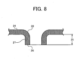
- Fig. 8 is a sectional view of a prepared hole (burring hole) formed by a conventional protruding method.
- a protruding height of 25 millimeter is secured by protruding the first material 24 using the conventional protruding method.
- the axial force is a force to press a second material to the first material.
- a tapping screw of the forming type for the thin metal sheets that has a single-start thread at a lead portion and double-start threads at the useful thread portion is conceived as a screw that can fasten the thin metal sheets without the burring.
- the tapping screw with the single-start thread and the double-start threads is flawed for being low in axial force.
- the failure of the female thread can occur in an attempt to increase the fastening torque under a condition that the thread is relatively larger in diameter, and especially the thickness of the sheet metal is as thin as 0.6 millimeter.
- a structure according to one aspect of the present invention is for fastening a second material to a first material by a tapping screw having a roale thread according to claim 1.
- the first material includes a hole with a surface in which a female thread is formed as the tapping screw is screwed in; and a concave portion around the hole.
- a structure according to the present invention includes a first material having a first hole with a surface; and a concave portion around the first hole; a second material having a second hole; and a tapping screw to be inserted into the second hole and screwed in the first hole to form female thread on the surface of the first hole and to fasten the second material to the first material.
- a method according to still another aspect of the present invention is a method according to claim 7 for forming a first material that fastens a second material with a tapping screw having a male thread, the method includes forming a hole in the first material for screwing the tapping screw, wherein the hole has a surface in which a female thread is formed as the tapping screw is screwed in; and forming a concave portion in the first material around the hole.
- Fig. 1 is a side view of an example of a tapping screw 1 for a thin sheet (hereinafter, "tapping screw 1"), which is used in embodiments of the present invention.
- a head portion 5 has a cross recessed hexagon head with a captive washer, a lead portion 6 of a thread portion has a single-start thread, and a useful thread portion 7 has double-start threads.
- the double-start threads 9 and 10, in the useful thread portion 7, are symmetrical with respect to a center axis 8.
- direction of the tapping screw 1 is corrected so as to become a right angle with a second material when the useful thread portion 7 reaches the second material, even if the tapping screw 1 is tilted against the second material at first, because resistance of one side increases.
- the tapping screw 1 easily traces the threads previously made because the lead portion 6 has single-start threads, this is considered to function extremely effectively in a repeated fastening.
- Fig. 2 is a sectional view of an embodiment of the tapping screw 1 shown in Fig. 1, which fastens a first material and a second material.
- the tapping screw 1 fastens a second material 2 with a first material 3.
- a concave portion 4 of the first material 3 is slightly deformed and being pressurized under a condition of being fastened due to an axial force of the tapping screw 1.
- Fig. 3 is a sectional view of a concave portion in a periphery of a prepared hole of a first material 11 thicknesses thereof is 0.6 millimeter or 0.8 millimeter.
- a concave portion 14 is formed by a drawing work.
- the concave portion 14 is trapezoid in shape, and an inlet of a thread is wider when viewed from a direction shown by an arrow 13.
- a diameter 15 of the concave portion 14 at the bottom is larger than a maximum outer diameter of the threaded portion of the tapping screw 1 by 0.5 millimeter to 0.2 millimeter.
- An angle of inclination of an inclined surface 16 of the concave portion 14 is about 45° ⁇ 15°, and a depth of the drawing 17 is set to be from 1/4 to 1/2 of a thickness of the first material 11.
- the prepared hole 12 is formed before the concave portion 14 is formed.
- Fig.4 is a sectional view of a concave portion of a peripheral of a prepared hole when a thickness of a first material 18 is 1.0 millimeter.
- a concave portion 21 is formed by a half blanking work.
- the direction of the half blanking work is the same as screwing direction 20 of the tapping screw 1.
- a diameter 22 of the concave portion 21 is larger than a maximum outer diameter of the threaded portion of the tapping screw 1 by 0.5 millimeter to 0.2 millimeter same as an example of Fig. 3, and a depth of the half blanking 23 is set to be 1/4 to 1/2 of a thickness of the first material 18.
- the diameters and depths of the concave portions 14 and 21 in the both Figs. 3 and 4 are determined from a viewpoint of being able to secure a flexural strength due to the shape effect of the prepared holes, and also being able to conduct the works easily. Furthermore, choices of a drawing work or the half blanking are determined from viewpoints of easiness of the work and securing of strength depending on the thicknesses of the first materials 11 and 18. Moreover, the drawing and the half blanking require less pressing power than a burring.
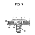
- Fig. 5 is for a purpose of comparison, and is a sectional view of a flat first material 29 being fastened and the material is provided with no concave portion.
- a periphery of a female thread 30 of the flat first material 29 is deformed because a flexural moment, a fulcrum thereof is an edge of a hole 33 on a material 32 to be fastened, works by an axial force of a tapping screw 31.
- the deformation by the flexural stress is a major cause of the failure of the female thread.
- the peripheries of the prepared holes 12 and 19 are resistant to the flexural stress, and the failure of the female thread is satisfactory prevented from occurring.
- Fig. 6 shows effects of the existence of the concave portion, which is explained as embodiments of this invention, on the failure torque of the female thread.
- Fig. 6 shows a result of measurements of the failure torque of the female thread when a nominal 3 millimeter in diameter tapping screw (not shown) is used.
- a reference number 34 indicates a failure torque characteristics of a female thread when a 0.6 millimeter thick first material with a concave is used.
- a failure of female thread occurred when fastened by a fastening torque of 11 kgf ⁇ cm (1.07 N ⁇ m), the failure torque in this case is presumed to be less than 1.1 N ⁇ m).
- the existence of the concave contributed to an improvement of performance of a failure of female thread by approximately 87% to 62% under a diameter of the prepared holes measured in this experiment.
- a reference number 35 indicates a failure torque characteristics of a female thread when a 0.8 millimeter thick first material with a concave is used
- a reference number 36 indicates a failure torque characteristics of a female thread when a 0.8 millimeter thick first material without a concave is used.
- Each diameter of the prepared hole shows an improvement of about 50% of the performance.
- the failure of the female thread occurs due to a lack of flexural strength of the female thread as a distance between an edge of the female thread and a portion to be pressed of the second material increases.
- the thickness of the sheet is 0.6 millimeter, when a prepared hole of 3.5 millimeters (diameter) ⁇ 5 millimeters (depth) is used, under a fastening torque of 1.1 N ⁇ m failures of the female thread occurred frequently without the concave, while no failure of the female thread occurred with the concave.
- Fig. 7 shows effects of the existence of the concave portion, which is explained as embodiments of this invention, on the loosening torque of the female thread.
- Fig. 7 shows a result of measurements of the loosening torque of the female thread when a nominal 3 millimeter diameter tapping screw (not shown) is used.
- a reference number 37 indicates loosening torque characteristics of the female thread when a 0.6 millimeter thick first material with a concave is used. In the case of the 0.6 millimeter thick first material without a concave, no measurement was possible because a failure of the female thread occurred, which means the loosening torque is zero.
- a reference number 38 indicates loosening torque characteristics of the female thread when a 0.8 millimeter thick first material with a concave is used
- a reference number 39 indicates loosening torque characteristics of the female thread when a 0.8 millimeter thick first material without a concave is used.
- an average failure torque of the female thread was 1.4 2 N ⁇ m without the concave, and the average failure torque of the female thread was 2.14 N ⁇ m with the concave, and loosening torque performance has improved by about 30% with the concave.
- an average loosening torque was 0.58 N ⁇ m without the concave, and was 0.77 N ⁇ m with the concave.
- the second material is thin, a bite of imperfect part of a male thread to the female thread is reduced, which enables the first material to fasten without the burring in the female thread.
- a lead portion thereof is of single-start thread and a useful thread thereof is of double-start threads.
- same effects can be obtained when other types of tapping screws are used.
- the second material is not limited to metal, but any other material including plastics.
- a structure for fastening metal sheets by a screw related to the present invention has effects of being possible of fastening with a secured axial force of the screw and of improving a loosening prevention performance.
Landscapes
- Engineering & Computer Science (AREA)
- General Engineering & Computer Science (AREA)
- Mechanical Engineering (AREA)
- Physics & Mathematics (AREA)
- Geometry (AREA)
- Connection Of Plates (AREA)
Claims (7)
- Struktur, die umfasst:ein erstes Material (3; 11; 18) miteinem ersten Loch (12; 19), das eine Oberfläche besitzt; undeinem konkaven Abschnitt (4; 14) um das erste Loch (12; 19);ein zweites Material (2) mit einem zweiten Loch; undeine Schneidschraube (1; 31), die in das zweite Loch eingesteckt werden soll und in das erste Loch (12; 19) geschraubt wird, um auf der Oberfläche des ersten Lochs (12; 19) ein Innengewinde zu bilden und um das zweite Material (2) an dem ersten Material (3; 11; 18) zu befestigen, dadurch gekennzeichnet, dass eine Tiefe des konkaven Abschnitts (4; 14) gleich 1/4 bis 1/2 einer Dicke des ersten Materials (3; 11; 18) in dem konkaven Abschnitt (4; 14) ist.
- Struktur nach Anspruch 1, bei der die Schneidschraube (1; 31) ein Außengewinde besitzt.
- Struktur nach Anspruch 1, bei der ein Durchmesser eines Bodens des konkaven Abschnitts (4; 14) größer als ein Außendurchmesser der Schneidschraube (1; 31) ist.
- Struktur nach Anspruch 1, bei der der konkave Abschnitt (4; 14) trapezförmig ist und ein Durchmesser eines Bodens des konkaven Abschnitts (4; 14) kleiner als ein Durchmesser einer Oberseite hiervon ist.
- Struktur nach Anspruch 1, bei der der konkave Abschnitt (4; 14) durch Halbschneiden gebildet ist.
- Struktur nach Anspruch 1, bei der die Schneidschraube (1; 31) ein Formungstyp ist und einen vorderen Abschnitt (6) sowie einen Nutzgewindeabschnitt (7) besitzt und das Außengewinde ein Einzelbeginn-Gewinde im vorderen Abschnitt (6) und Doppelbeginn-Gewinde (9, 10) im NutzGewindeabschnitt (7) aufweist.
- Verfahren zum Formen eines ersten Materials (3; 11; 18), an dem ein zweites Material (2) mittels einer Schneidschraube (1), die ein Außengewinde besitzt, befestigt wird, wobei das Verfahren umfasst:Bilden eines Lochs (12; 19) in dem ersten Material (3; 11; 18), um die Schneidschraube (1; 31) einzuschrauben, wobei das Loch (12; 19) eine Oberfläche besitzt, auf der ein Außengewinde gebildet wird, wenn die Schneidschraube (1; 31) eingeschraubt wird; undBilden eines konkaven Abschnitts (4; 14) in dem ersten Material (3; 11; 18) um das Loch, dadurch gekennzeichnet, dass eine Tiefe des konkaven Abschnitts (4; 14) gleich 1/4 bis 1/2 einer Dicke des ersten Materials (3; 11; 18) in dem konkaven Abschnitt (4; 14) ist.
Applications Claiming Priority (4)
| Application Number | Priority Date | Filing Date | Title |
|---|---|---|---|
| JP2002266964 | 2002-09-12 | ||
| JP2002266964 | 2002-09-12 | ||
| JP2003203482A JP4340103B2 (ja) | 2002-09-12 | 2003-07-30 | ねじ締結構造 |
| JP2003203482 | 2003-07-30 |
Publications (2)
| Publication Number | Publication Date |
|---|---|
| EP1398514A1 EP1398514A1 (de) | 2004-03-17 |
| EP1398514B1 true EP1398514B1 (de) | 2006-11-29 |
Family
ID=31890571
Family Applications (1)
| Application Number | Title | Priority Date | Filing Date |
|---|---|---|---|
| EP03020418A Expired - Lifetime EP1398514B1 (de) | 2002-09-12 | 2003-09-11 | Schraubbefestigungsstruktur |
Country Status (4)
| Country | Link |
|---|---|
| US (1) | US6945729B2 (de) |
| EP (1) | EP1398514B1 (de) |
| JP (1) | JP4340103B2 (de) |
| DE (1) | DE60309990T2 (de) |
Families Citing this family (15)
| Publication number | Priority date | Publication date | Assignee | Title |
|---|---|---|---|---|
| JP2005078763A (ja) * | 2003-09-03 | 2005-03-24 | Hitachi Global Storage Technologies Netherlands Bv | ディスク装置 |
| DE102006034584A1 (de) * | 2006-07-26 | 2008-01-31 | Ejot Gmbh & Co. Kg | Loch- und gewindeformende Schraube |
| DE102006000438A1 (de) * | 2006-09-04 | 2008-03-06 | Hilti Ag | Spreizschraube |
| JP2009123736A (ja) * | 2007-11-12 | 2009-06-04 | Nec Corp | デバイスの実装構造及びデバイスの実装方法 |
| EP2068012A3 (de) * | 2007-12-03 | 2011-11-23 | BSH Bosch und Siemens Hausgeräte GmbH | Schraube mit einem gehärteten Gewindeteil |
| ITTO20090022U1 (it) * | 2009-02-17 | 2010-08-18 | Savio Spa | Sistema di fissaggio di accessori su telai in materiale metallico per porte, finestre e simili |
| DE102009015376A1 (de) * | 2009-03-27 | 2010-09-30 | Ejot Gmbh & Co. Kg | Schraubverbindung zur festen Verbindung zweier Baugruppen |
| DE102009002078A1 (de) | 2009-04-01 | 2010-10-07 | Ford Global Technologies, LLC, Dearborn | Verbindungsvorrichtung |
| IT1403796B1 (it) * | 2011-01-12 | 2013-10-31 | Savio Spa | "sistema di fissaggio di accessori su telai in materiale metallico per porte, finestre e simili" |
| DE202012001847U1 (de) * | 2012-02-23 | 2012-03-05 | Ruia Global Fasteners Ag | Selbstfurchende Schraube |
| US8864502B2 (en) * | 2012-05-04 | 2014-10-21 | Thomas & Betts International, Inc. | Mechanical grounding connector |
| JP5607114B2 (ja) * | 2012-06-26 | 2014-10-15 | 株式会社トープラ | タッピンねじ |
| JP2014066306A (ja) * | 2012-09-26 | 2014-04-17 | Canon Inc | ネジ締結構成 |
| JP5909747B2 (ja) * | 2014-07-28 | 2016-04-27 | 株式会社青山製作所 | 軟質金属用セルフタップねじ |
| US9488210B2 (en) * | 2014-09-30 | 2016-11-08 | Ford Global Technologies, Llc | Flow drill screw assembly and method |
Family Cites Families (21)
| Publication number | Priority date | Publication date | Assignee | Title |
|---|---|---|---|---|
| US3438299A (en) * | 1968-01-26 | 1969-04-15 | Illinois Tool Works | Extruding screw |
| JPS5392128A (en) | 1977-01-25 | 1978-08-12 | Ricoh Co Ltd | Illuminator for copying machine |
| US4174148A (en) * | 1977-12-16 | 1979-11-13 | Amerace Corporation | Electrical terminal clamp assembly |
| JPS5950434A (ja) | 1982-09-17 | 1984-03-23 | Ricoh Co Ltd | 複写機の変倍光学装置 |
| US4891739A (en) | 1984-10-12 | 1990-01-02 | Ricoh Company, Ltd. | Illuminating device |
| DE3536583A1 (de) | 1984-10-12 | 1986-04-17 | Ricoh Co., Ltd., Tokio/Tokyo | Beleuchtungseinrichtung |
| US4782369A (en) | 1986-11-04 | 1988-11-01 | Ricoh Company, Ltd. | Device for illuminating an original document |
| JPH0512655Y2 (de) * | 1987-03-19 | 1993-04-02 | ||
| JP2532100B2 (ja) | 1987-06-19 | 1996-09-11 | 株式会社リコー | 照度分布補正用透過型フィルタ |
| DE3726405A1 (de) * | 1987-08-07 | 1989-02-16 | Salice Arturo Spa | Grund- oder befestigungsplatte mit teilweise eingeschraubter befestigungsschraube fuer zu befestigende teile |
| US4949120A (en) | 1988-04-21 | 1990-08-14 | Ricoh Company, Ltd. | Illuminating device |
| JP2834766B2 (ja) | 1988-11-09 | 1998-12-14 | 株式会社リコー | 画像形成装置における変倍露光装置 |
| JPH03264970A (ja) | 1990-03-15 | 1991-11-26 | Ricoh Co Ltd | レーザ書込装置 |
| US5280362A (en) | 1990-06-15 | 1994-01-18 | Ricoh Company, Ltd. | Digital copier for copying a bicolored document at the same speed as a monocolored document |
| JP3515788B2 (ja) | 1991-06-25 | 2004-04-05 | 株式会社リコー | 書込装置 |
| JP3231856B2 (ja) | 1991-10-31 | 2001-11-26 | 株式会社リコー | 画像形成装置 |
| US5376994A (en) | 1992-02-13 | 1994-12-27 | Ricoh Company, Ltd. | Compact BI-color electrophotographic image forming apparatus |
| JPH0625564A (ja) | 1992-07-09 | 1994-02-01 | Asahi Pen:Kk | 塗料組成物 |
| DE19645886C2 (de) | 1996-11-07 | 1998-10-08 | Bosch Gmbh Robert | Schraubverbindung mit Befestigungsschraube |
| US6164684A (en) * | 1998-08-31 | 2000-12-26 | Trw Vehicle Safety Systems Inc. | Fastening structure for interconnecting parts of a vehicle occupant protection apparatus |
| DE29916682U1 (de) * | 1999-09-22 | 2001-02-08 | Andreas Stihl AG & Co., 71336 Waiblingen | Anordnung zur Sicherung eines Bauteils |
-
2003
- 2003-07-30 JP JP2003203482A patent/JP4340103B2/ja not_active Expired - Fee Related
- 2003-09-11 DE DE60309990T patent/DE60309990T2/de not_active Expired - Lifetime
- 2003-09-11 EP EP03020418A patent/EP1398514B1/de not_active Expired - Lifetime
- 2003-09-12 US US10/660,680 patent/US6945729B2/en not_active Expired - Fee Related
Also Published As
| Publication number | Publication date |
|---|---|
| DE60309990D1 (de) | 2007-01-11 |
| US20040126184A1 (en) | 2004-07-01 |
| JP2004156775A (ja) | 2004-06-03 |
| US6945729B2 (en) | 2005-09-20 |
| DE60309990T2 (de) | 2007-06-14 |
| EP1398514A1 (de) | 2004-03-17 |
| JP4340103B2 (ja) | 2009-10-07 |
Similar Documents
| Publication | Publication Date | Title |
|---|---|---|
| EP1398514B1 (de) | Schraubbefestigungsstruktur | |
| EP0859916B1 (de) | Befestigungssystem mit schrauben | |
| JP5572873B2 (ja) | 締結部材および締結構造 | |
| RU2042056C1 (ru) | Винт для изготовления гладких или резьбовых отверстий | |
| US4798507A (en) | Sheet metal U-nut | |
| US7021877B2 (en) | Self-tapping screw | |
| JP4878407B2 (ja) | 締結部材および締結構造 | |
| US4770584A (en) | Demountable pin, particularly suitable for the lever mechanisms of textile machines | |
| US8491247B2 (en) | Fastener with improved torque bearing surface | |
| US20140334898A1 (en) | Fastener | |
| KR20000005419A (ko) | 기초에 금속 및 플라스틱 섹션 또는 플레이트를 고정하기 위한스크류 | |
| US20100196120A1 (en) | Fastener relief path | |
| US6155761A (en) | Short point anti-cross-threading design | |
| US6494655B1 (en) | Self-tapping screw and method for joining thin workpieces | |
| US6135892A (en) | Method of forming a short point anti-cross threading member | |
| US20160169263A1 (en) | Threaded fastener | |
| JP2006220210A (ja) | 介在部材、締付具、及び被締付体 | |
| JP4512991B2 (ja) | タッピンねじ | |
| EP1886031B1 (de) | Feststeller und verfahren zur verringerung von aus belastungen resultierenden fehlern in einem motor | |
| JP4657271B2 (ja) | 締め付け構造及び建築部材連結構造 | |
| JP2007321930A (ja) | 薄板締結用タッピンねじ | |
| EP1557575B1 (de) | Schraube mit einer Vielzahl von Schraubwinkeln und Walzbacken zu ihrer Herstellung | |
| KR102185997B1 (ko) | 태핑 스크류 | |
| JP7647159B2 (ja) | ネジ | |
| EP3988804B1 (de) | Schraube |
Legal Events
| Date | Code | Title | Description |
|---|---|---|---|
| PUAI | Public reference made under article 153(3) epc to a published international application that has entered the european phase |
Free format text: ORIGINAL CODE: 0009012 |
|
| AK | Designated contracting states |
Kind code of ref document: A1 Designated state(s): AT BE BG CH CY CZ DE DK EE ES FI FR GB GR HU IE IT LI LU MC NL PT RO SE SI SK TR |
|
| AX | Request for extension of the european patent |
Extension state: AL LT LV MK |
|
| 17P | Request for examination filed |
Effective date: 20040217 |
|
| AKX | Designation fees paid |
Designated state(s): DE ES FR GB IT NL |
|
| GRAP | Despatch of communication of intention to grant a patent |
Free format text: ORIGINAL CODE: EPIDOSNIGR1 |
|
| GRAS | Grant fee paid |
Free format text: ORIGINAL CODE: EPIDOSNIGR3 |
|
| GRAA | (expected) grant |
Free format text: ORIGINAL CODE: 0009210 |
|
| AK | Designated contracting states |
Kind code of ref document: B1 Designated state(s): DE ES FR GB IT NL |
|
| PG25 | Lapsed in a contracting state [announced via postgrant information from national office to epo] |
Ref country code: IT Free format text: LAPSE BECAUSE OF FAILURE TO SUBMIT A TRANSLATION OF THE DESCRIPTION OR TO PAY THE FEE WITHIN THE PRESCRIBED TIME-LIMIT;WARNING: LAPSES OF ITALIAN PATENTS WITH EFFECTIVE DATE BEFORE 2007 MAY HAVE OCCURRED AT ANY TIME BEFORE 2007. THE CORRECT EFFECTIVE DATE MAY BE DIFFERENT FROM THE ONE RECORDED. Effective date: 20061129 Ref country code: NL Free format text: LAPSE BECAUSE OF FAILURE TO SUBMIT A TRANSLATION OF THE DESCRIPTION OR TO PAY THE FEE WITHIN THE PRESCRIBED TIME-LIMIT Effective date: 20061129 |
|
| REG | Reference to a national code |
Ref country code: GB Ref legal event code: FG4D |
|
| REF | Corresponds to: |
Ref document number: 60309990 Country of ref document: DE Date of ref document: 20070111 Kind code of ref document: P |
|
| PG25 | Lapsed in a contracting state [announced via postgrant information from national office to epo] |
Ref country code: ES Free format text: LAPSE BECAUSE OF FAILURE TO SUBMIT A TRANSLATION OF THE DESCRIPTION OR TO PAY THE FEE WITHIN THE PRESCRIBED TIME-LIMIT Effective date: 20070312 |
|
| ET | Fr: translation filed | ||
| NLV1 | Nl: lapsed or annulled due to failure to fulfill the requirements of art. 29p and 29m of the patents act | ||
| PLBE | No opposition filed within time limit |
Free format text: ORIGINAL CODE: 0009261 |
|
| STAA | Information on the status of an ep patent application or granted ep patent |
Free format text: STATUS: NO OPPOSITION FILED WITHIN TIME LIMIT |
|
| 26N | No opposition filed |
Effective date: 20070830 |
|
| PGFP | Annual fee paid to national office [announced via postgrant information from national office to epo] |
Ref country code: DE Payment date: 20140922 Year of fee payment: 12 |
|
| PGFP | Annual fee paid to national office [announced via postgrant information from national office to epo] |
Ref country code: FR Payment date: 20140919 Year of fee payment: 12 Ref country code: GB Payment date: 20140919 Year of fee payment: 12 |
|
| REG | Reference to a national code |
Ref country code: DE Ref legal event code: R119 Ref document number: 60309990 Country of ref document: DE |
|
| GBPC | Gb: european patent ceased through non-payment of renewal fee |
Effective date: 20150911 |
|
| REG | Reference to a national code |
Ref country code: FR Ref legal event code: ST Effective date: 20160531 |
|
| PG25 | Lapsed in a contracting state [announced via postgrant information from national office to epo] |
Ref country code: DE Free format text: LAPSE BECAUSE OF NON-PAYMENT OF DUE FEES Effective date: 20160401 Ref country code: GB Free format text: LAPSE BECAUSE OF NON-PAYMENT OF DUE FEES Effective date: 20150911 |
|
| PG25 | Lapsed in a contracting state [announced via postgrant information from national office to epo] |
Ref country code: FR Free format text: LAPSE BECAUSE OF NON-PAYMENT OF DUE FEES Effective date: 20150930 |