EP1398538A2 - Kettenspannvorrichtung - Google Patents
Kettenspannvorrichtung Download PDFInfo
- Publication number
- EP1398538A2 EP1398538A2 EP20030018131 EP03018131A EP1398538A2 EP 1398538 A2 EP1398538 A2 EP 1398538A2 EP 20030018131 EP20030018131 EP 20030018131 EP 03018131 A EP03018131 A EP 03018131A EP 1398538 A2 EP1398538 A2 EP 1398538A2
- Authority
- EP
- European Patent Office
- Prior art keywords
- tensioner
- arm
- lifter
- chain
- transmission chain
- Prior art date
- Legal status (The legal status is an assumption and is not a legal conclusion. Google has not performed a legal analysis and makes no representation as to the accuracy of the status listed.)
- Granted
Links
Images


Classifications
-
- F—MECHANICAL ENGINEERING; LIGHTING; HEATING; WEAPONS; BLASTING
- F16—ENGINEERING ELEMENTS AND UNITS; GENERAL MEASURES FOR PRODUCING AND MAINTAINING EFFECTIVE FUNCTIONING OF MACHINES OR INSTALLATIONS; THERMAL INSULATION IN GENERAL
- F16H—GEARING
- F16H7/00—Gearings for conveying rotary motion by endless flexible members
- F16H7/08—Means for varying tension of belts, ropes or chains
- F16H7/0848—Means for varying tension of belts, ropes or chains with means for impeding reverse motion
-
- F—MECHANICAL ENGINEERING; LIGHTING; HEATING; WEAPONS; BLASTING
- F16—ENGINEERING ELEMENTS AND UNITS; GENERAL MEASURES FOR PRODUCING AND MAINTAINING EFFECTIVE FUNCTIONING OF MACHINES OR INSTALLATIONS; THERMAL INSULATION IN GENERAL
- F16H—GEARING
- F16H7/00—Gearings for conveying rotary motion by endless flexible members
- F16H7/08—Means for varying tension of belts, ropes or chains
- F16H2007/0802—Actuators for final output members
- F16H2007/0812—Fluid pressure
-
- F—MECHANICAL ENGINEERING; LIGHTING; HEATING; WEAPONS; BLASTING
- F16—ENGINEERING ELEMENTS AND UNITS; GENERAL MEASURES FOR PRODUCING AND MAINTAINING EFFECTIVE FUNCTIONING OF MACHINES OR INSTALLATIONS; THERMAL INSULATION IN GENERAL
- F16H—GEARING
- F16H7/00—Gearings for conveying rotary motion by endless flexible members
- F16H7/08—Means for varying tension of belts, ropes or chains
- F16H7/0848—Means for varying tension of belts, ropes or chains with means for impeding reverse motion
- F16H2007/0859—Check valves
-
- F—MECHANICAL ENGINEERING; LIGHTING; HEATING; WEAPONS; BLASTING
- F16—ENGINEERING ELEMENTS AND UNITS; GENERAL MEASURES FOR PRODUCING AND MAINTAINING EFFECTIVE FUNCTIONING OF MACHINES OR INSTALLATIONS; THERMAL INSULATION IN GENERAL
- F16H—GEARING
- F16H7/00—Gearings for conveying rotary motion by endless flexible members
- F16H7/08—Means for varying tension of belts, ropes or chains
- F16H2007/0863—Finally actuated members, e.g. constructional details thereof
- F16H2007/0872—Sliding members
Definitions
- the present invention relates to the improvement of a chain tensioner provided wi th a tensioner arm rockably supported by fixed structure and slidably touched to the outside on the loose side of a transmission chain without an end coupling a driving sprocket and a driven sprocket and a tensioner lifter supported by fixed structure for pressing the tensioner arm upon the side of the transmission chain.
- a tensioner lifter In a conventional type chain tensioner, a tensioner lifter directly presses the back of a tensioner arm. To facilitate the absorption of the oscillation of a transmission chain, it is desirable that the flexibility of the tensioner arm is enhanced and its oscillation absorption function is enhanced, however, then, in the conventional type, the tensioner lifter is directly oscillated by the tensioner arm, a load of the tensioner lifter is increased and the follow-up of the tensioner lifter for the transmission chain may be deteriorated.
- the invention is made in view of such a situation and the object is to provide a chain tensioner in which a load of a tensioner lifter is reduced, enhancing the oscillation absorption function of the tensioner lifter and the follow-up of the tensioner lifter for a transmission chain can be satisfactorily maintained.
- the invention is based upon a chain tensioner provided with a tensioner arm rockably supported by fixed structure and slidably touched to the outside on the loose side of a transmission chain without an end coupling a driving sprocket and a driven sprocket and a tensioner lifter supported by the fixed structure for pressing the tensioner arm upon the side of the transmission chain and is first characterized in that a control arm rockably supported by the fixed structure for transmitting the pressure of the tensioner lifter to the tensioner arm is inserted between the tensioner arm and the tensioner lifter.
- the oscillation of the transmission chain can be absorbed by applying suitable flexibility to the tensioner arm.
- the control arm is inserted between the tensioner arm and the tensioner lifter, the repulsion of the transmission chain for the tensioner arm is transmitted to the tensioner lifter after the repulsion is buffered by the suitable flexibility of the control arm and a load of the tensioner lifter can be reduced. Therefore, the follow-up of the transmission chain by the tensioner lifter can be satisfactorily performed, securing the desired useful life of the tensioner lifter.
- the invention is second characterized in that a point of the application of the pressure of the tensioner lifter upon the control arm is set to the middle of the center of the oscillation of the control arm and a point at which the control arm presses the tensioner arm.
- the tensioner arm can be greatly moved via the control arm at a relatively small stroke of a lifter rod of the tensioner lifter owing to the arm ratio of the control arm, as a result, the follow-up of the transmission chain by the tensioner lifter is further enhanced, not only the repulsion of the transmission chain is not directly transmitted to the tensioner lifter but the useful life of the tensioner lifter can be extended.
- the invention is third characterized in that a pressing part for pressing the outside of the transmission chain so that the pressing part can be slid is provided to the control arm between the end of the tensioner arm and the sprocket in the vicinity of the end.
- the contact ratio of the transmission chain and the driving or driven sprocket in the vicinity of the end of the tensioner arm is enhanced and the invention can contribute to the enhancement of chain transmission efficiency.
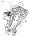
- Fig. 1 is a side view showing a timing transmission gear for a valve gear of an engine provided with a chain tensioner according to the invention
- Fig. 2 is a plan showing a tensioner arm of the chain tensioner
- Fig. 3 is a side view showing the tensioner arm
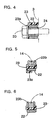
- Fig. 4 is a sectional view viewed along a line 4-4 in Fig. 3
- Fig. 5 is a sectional view viewed along a line 5-5 in Fig. 3
- Fig. 6 is a sectional view viewed along a line 6-6 in Fig.
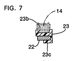
- Fig. 7 is a sectional view viewed along a line 7-7 in Fig.
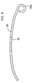
- Fig. 8 is a plan showing the body of the tensioner arm
- Fig. 9 is a side view showing the body of the tensioner arm
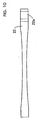
- Fig. 10 shows another embodiment of the invention corresponding to Fig. 8.
- an engine E for a motorcycle is arranged in a state in which the head is inclined in front of a vehicle.
- the body Ea of the engine E is composed of a crankcase 1, a cyl inder block 2 and a cyl inder head 3 , a crankshaf t 4 is supported by the crankcase 1, a camshaft for intake air 5 and a camshaft for exhaust 6 are supported by the cylinder head 3, and the crankshaft 4, the camshaft for intake air 5 and the camshaft for exhaust 6 are coupled by a timing transmission gear 10.
- the timing transmission gear 10 is composed of a driving sprocket 11 fixed to the crankshaft 4, first and second driven sprockets 12, 13 respectively fixed to the camshaft for intake air 5 and the camshaft for exhaust 6 and a transmission chain 14 without an end wound on the driving sprocket 11, the first and second driven sprockets 12, 13 .
- the first and second driven sprockets 12, 13 both have double teeth of the number of the teeth of the driving sprocket 11 and are driven in a direction shown by an arrow A at half reduction ratio from the driving sprocket 11.
- a chain tensioner 15 On the loose side of the transmission chain 14, a chain tensioner 15 according to the invention for applying fixed tension to it is arranged.
- the chain tensioner 15 is composed of a tensioner arm 16, a control arm 17 and a tensioner lifter 18.
- the tensioner arm 16 is composed of a band tensioner arm body 22 rockably supported via a first pivot 20 by the cylinder block 2 in the vicinity of the driving sprocket 11 and made of a spring steel plate and curved toward the outside on the loose side of the transmission chain 14 and a tensioner shoe 23 made of flexible synthetic resin that covers the front of the tensioner arm body 22 and is slidingly touched to the outside on the loose side of the transmission chain 14, and as a whole, suitable flexibility that can absorb the oscillation of the transmission chain 14 is applied.
- the tensioner arm body 22 and the tensioner shoe 23 are respectively provided with a boss 22a and a boss 23a supported via a collar 24 by the first pivot 20 at each end, a chain guide groove 23b to which the loose side of the transmission chain 14 is fitted so that the loose side can be slid is formed on the front of the tensioner shoe 23 and at the back of the tensioner shoe, plural holding claws 23c that hold the tensioner arm body 22 lapped over the tensioner shoe are formed.
- an arc-shaped cut-out 25 is formed in the middle from the first pivot 20 to a point N pressed by the control arm 17 on both sides of the tensioner arm body 22 and hereby, the width in the middle of the tensioner arm body 22 is set so that it is smaller than the width at both ends of the arm body 22.
- the control arm 17 is made of a spring steel plate like the tensioner arm body 22 , is supported in the vicinity of the first driven sprocket 12 via a second pivot 21 by the cylinder head 3 so that the control arm can be oscillated and the oscillated end is touched to the back on the side of the oscillated end of the tensioner arm body 22.
- a pressure plate 27 is bonded to the back in the middle of the control arm 17 via cushion material 26 such as rubber and the tensioner lifter 18 for pressing the pressure plate 27 on the side of the tensioner arm 16 is attached to the cylinder head 3.
- a point P of the application of the pressure of the tensioner lifter 18 upon the control arm 17 is set in the middle of the center O of the second pivot 21 which is the center of the oscillation of the control arm 17 and the pressure point N of the control arm 17 upon the tensioner arm 16.
- the control arm 17 is provided with an auxiliary shoe 28 made of synthetic resin and slidingly touched to the outside of the transmission chain 14 between the first driven sprocket 12 and the end of the tensioner arm 16.
- the tensioner lifter 18 is composed of a lifter case 29 fixed to the cylinder head 3 , a hollow lifter rod 3 0 supported by the lifter case 29 so that the rod cannot be turned and opposite to the pressure plate 27, a screw shaft 31 screwed to a hollow part of the lifter rod 30 and a twisted coil spring 32 for turning and pressing the screw shaft 31 in a traveling direction of the lifter rod 30 in the lifter case 29 as heretofore well-known. Therefore, the torsional moment of the twisted coil spring 32 is converted to a thrust load by the screw shaft 31 and is amplified to be pressure that presses the lifter rod 30 on the side of the control arm 17.
- timing transmission gear 10 While the timing transmission gear 10 is operated, that is, when the driving sprocket 11 drives the first and second driven sprockets 12 , 13 via the transmission chain 14, the engaged state of each sprocket 11 to 13 of the transmission chain 14 is always kept suitable and efficient chain transmission is achieved by transmitting pressure which the tensioner lifter 18 applies to the pressure plate 27 of the control arm 17 by the lifter rod 30 to the tensioner arm 16 via the control arm 17, transmitting it to the loose side of the transmission chain 14 and applying fixed tension to the transmission chain 14.
- the oscillation caused during transmission of the transmission chain 14 is effectively absorbed by the suitable deflection of the flexible tensioner arm 16.
- the control arm 17 is inserted between the tensioner arm 16 and the tensioner lifter 18, the repulsion of the transmission chain 14 for the tensioner arm 16 is transmitted to the tensioner lifter 18 after the repulsion is buffered by the suitable deflection of the control arm 17 and a load of the tensioner lifter 18 can be reduced. Therefore, the follow-up of the tensioner lifter 18 for the transmission chain 14 can be satisfactorily performed, securing the desired useful life of the tensioner lifter 18.
- the tensioner arm 16 can be greatly moved via the control arm 17 at a relatively small stroke of the lifter rod 30 of the tensioner lifter 18 owing to the arm ratio of the control arm 17, as a result, the follow-up of the tensioner lifter 18 for the transmission chain 14 is further enhanced, and not only the repulsion of the transmission chain 14 is not directly transmitted to the tensioner lifter 18 but the useful life of the tensioner lifter 18 can be extended.
- control arm 17 presses the auxiliary shoe 28 upon the outside of the transmission chain 14 between the first driven sprocket 12 and the tensioner arm 16 by the pressure of the tensioner lifter 18, contact ratio between the transmission chain 14 and the f irst driven sprocket 12 is enhanced and the control arm contributes to the enhancement of chain transmission efficiency.
- the tensioner arm 16 is composed of the tensioner arm body 22 made of a spring steel plate and the flexible tensioner shoe 23 made of synthetic resin that covers the front of the tensioner arm body 22 and is directly slidingly touched to the transmission chain 14 and the arc-shaped cut-out 25 the width of which is smaller than the width of each end is provided on both sides of the middle of the tensioner arm body 22, the flexibility in the middle of the tensioner arm body 22 is enhanced, the oscillation absorption function for the transmission chain 14 can be enhanced, the natural frequency of the tensioner arm body 22 is different in each part because the width of the tensioner arm body 22 is dif ferent in each part and the tensioner arm can also contribute to the prevention of the resonance of the tensioner arm body 22.
- desired flexibility can be simply applied to the middle of the tensioner arm body 22 by selecting the depth and the number of the cut-outs 25.
- this embodiment is characterized in that the width of a tensioner arm body 22 is gradually reduced from the both ends of the arm body 22 toward the center and as the configuration of the other parts is similar to that in the prior embodiment, the same reference number is allocated to a part corresponding to that in the prior embodiment in Fig. 10 and the description is omitted. According to this embodiment, the similar effect to that in the prior embodiment can be also achieved.
- the invention is not limited to the above-mentioned embodiments and various design changes are possible in a range which does not deviate from the object of the invention.
- the first pivot 20 for supporting the tensioner arm 16 may be also arranged on the side of the first driven sprocket 12 and the second pivot 21 for supporting the control arm 17 may be also arranged on the side of the driving sprocket 11.
- the oscillation of the transmission chain can be absorbed by applying suitable flexibility to the tensioner arm.
- the control arm is inserted between the tensioner arm and the tensioner lifter, the repulsion of the transmission chain for the tensioner arm is transmitted to the tensioner lifter after the repulsion is buffered by the suitable deflection of the control arm and a load of the tensioner lifter can be reduced. Therefore, the follow-up of the tensioner lifter for the transmission chain can be satisfactorily performed, securing the desired useful life of the tensioner lifter.
- the tensioner arm in addition to the first characteristic, as the point of the application of the pressure of the tensioner lifter upon the control arm is set to the middle of the center of the oscillation of the control arm and the point at which the control arm presses the tensioner arm, the tensioner arm can be greatly moved via the control arm at a relatively small stroke of the lifter rod of the tensioner lifter owing to the arm ratio of the control arm, as a result, the follow-up of the tensioner lifter for the transmission chain is further enhanced, and the repulsion of the transmission chain is not directly transmitted to the tensioner lifter but the useful life of the tensioner lifter can be extended.
- the pressing part for slidably pressing the outside of the transmission chain is provided to the control arm between the end of the tensioner arm and the sprocket in the vicinity of the end, the contact ratio of the transmission chain and the driving or driven sprocket close to the end of the tensioner arm is enhanced and chain transmission efficiency can be enhanced.
Landscapes
- Engineering & Computer Science (AREA)
- General Engineering & Computer Science (AREA)
- Mechanical Engineering (AREA)
- Devices For Conveying Motion By Means Of Endless Flexible Members (AREA)
- Lift-Guide Devices, And Elevator Ropes And Cables (AREA)
Applications Claiming Priority (2)
| Application Number | Priority Date | Filing Date | Title |
|---|---|---|---|
| JP2002266035A JP4065169B2 (ja) | 2002-09-11 | 2002-09-11 | チェーンテンショナ装置 |
| JP2002266035 | 2002-09-11 |
Publications (3)
| Publication Number | Publication Date |
|---|---|
| EP1398538A2 true EP1398538A2 (de) | 2004-03-17 |
| EP1398538A3 EP1398538A3 (de) | 2008-01-23 |
| EP1398538B1 EP1398538B1 (de) | 2009-12-09 |
Family
ID=31884786
Family Applications (1)
| Application Number | Title | Priority Date | Filing Date |
|---|---|---|---|
| EP03018131A Expired - Lifetime EP1398538B1 (de) | 2002-09-11 | 2003-08-08 | Kettenspannvorrichtung |
Country Status (9)
| Country | Link |
|---|---|
| US (1) | US7074146B2 (de) |
| EP (1) | EP1398538B1 (de) |
| JP (1) | JP4065169B2 (de) |
| CN (1) | CN1309975C (de) |
| BR (1) | BR0302883B1 (de) |
| CA (1) | CA2436929C (de) |
| DE (1) | DE60330423D1 (de) |
| ES (1) | ES2336088T3 (de) |
| MX (1) | MXPA03007559A (de) |
Cited By (1)
| Publication number | Priority date | Publication date | Assignee | Title |
|---|---|---|---|---|
| WO2007033879A1 (de) * | 2005-09-21 | 2007-03-29 | Schaeffler Kg | Zugmitteltrieb für eine brennkraftmaschine |
Families Citing this family (15)
| Publication number | Priority date | Publication date | Assignee | Title |
|---|---|---|---|---|
| JP3999610B2 (ja) * | 2002-09-11 | 2007-10-31 | 本田技研工業株式会社 | チェーンテンショナ装置 |
| JP2006250208A (ja) * | 2005-03-09 | 2006-09-21 | Tsubakimoto Chain Co | 伝動装置用ガイド |
| US7641577B2 (en) * | 2005-06-28 | 2010-01-05 | Borgwarner Inc. | Mechanical chain tensioner with compliant blade spring |
| US7628719B2 (en) * | 2005-10-26 | 2009-12-08 | Borgwarner, Inc. | Mechanical strap tensioner for multi-strand tensioning |
| JP4573901B2 (ja) | 2008-04-14 | 2010-11-04 | 本田技研工業株式会社 | チェーンテンショナ装置 |
| KR100986379B1 (ko) | 2008-10-01 | 2010-10-08 | 현대자동차주식회사 | 자동차의 타이밍수단용 장력해제 장치 |
| WO2010059698A1 (en) * | 2008-11-18 | 2010-05-27 | Cloyes Gear And Products, Inc. | Blade tensioner with captured spring |
| JP5143200B2 (ja) * | 2009-09-09 | 2013-02-13 | 本田技研工業株式会社 | チェーンテンショナ装置 |
| JP2014145398A (ja) * | 2013-01-28 | 2014-08-14 | Tsubakimoto Chain Co | チェーンガイド |
| DE102013004456B3 (de) * | 2013-03-14 | 2014-09-18 | Iwis Motorsysteme Gmbh & Co. Kg | Spannschiene mit federndem Aufdrückbereich |
| US9850989B2 (en) * | 2014-10-22 | 2017-12-26 | Schaeffler Technologies AG & Co. KG | Compliant tensioner arm |
| CN104832611B (zh) * | 2015-04-10 | 2017-06-13 | 浙江亚特电器有限公司 | 一种免工具自动张紧系统 |
| JP6408974B2 (ja) * | 2015-10-21 | 2018-10-17 | 株式会社椿本チエイン | チェーンガイド |
| CN106051075B (zh) * | 2016-07-14 | 2020-02-14 | 广东格兰仕微波炉电器制造有限公司 | 带传动的减震结构 |
| JP7260749B2 (ja) * | 2019-02-12 | 2023-04-19 | 株式会社椿本チエイン | チェーンガイド |
Citations (2)
| Publication number | Priority date | Publication date | Assignee | Title |
|---|---|---|---|---|
| JPS6329963B2 (de) | 1985-01-14 | 1988-06-16 | Yanmar Agricult Equip | |
| DE19652852A1 (de) | 1995-12-18 | 1997-06-19 | Borg Warner Automotive | Hydraulischer Kettenspanner |
Family Cites Families (9)
| Publication number | Priority date | Publication date | Assignee | Title |
|---|---|---|---|---|
| JPS57134055A (en) * | 1981-02-10 | 1982-08-19 | Honda Motor Co Ltd | Tensioner device for endless belt |
| JPS59174445U (ja) | 1983-05-10 | 1984-11-21 | 本田技研工業株式会社 | チエ−ンテンシヨナ−装置 |
| JPS60155046A (ja) * | 1984-01-25 | 1985-08-14 | Borg Warner Ootomooteibu Kk | チエーンテンシヨナの押圧付勢装置 |
| JPH07117129B2 (ja) * | 1986-06-24 | 1995-12-18 | ヤマハ発動機株式会社 | 頭上カム軸式エンジンのチエ−ンガイド |
| JP2843462B2 (ja) * | 1992-06-16 | 1999-01-06 | 大同工業株式会社 | テンショナー |
| JPH102386A (ja) * | 1996-06-13 | 1998-01-06 | Tsubakimoto Chain Co | 緩衝機構付ラチェット式テンショナ |
| JPH1068452A (ja) * | 1996-08-28 | 1998-03-10 | Hokushin Ind Inc | チェーンのテンショナー |
| US6155941A (en) * | 1998-12-15 | 2000-12-05 | Borgwarner Inc. | Hydraulic tensioner having a flexible blade arm |
| JP4651778B2 (ja) * | 2000-06-15 | 2011-03-16 | ボルグワーナー・モールステック・ジャパン株式会社 | ブレードテンショナ |
-
2002
- 2002-09-11 JP JP2002266035A patent/JP4065169B2/ja not_active Expired - Fee Related
-
2003
- 2003-08-08 DE DE60330423T patent/DE60330423D1/de not_active Expired - Lifetime
- 2003-08-08 EP EP03018131A patent/EP1398538B1/de not_active Expired - Lifetime
- 2003-08-08 ES ES03018131T patent/ES2336088T3/es not_active Expired - Lifetime
- 2003-08-11 CA CA002436929A patent/CA2436929C/en not_active Expired - Fee Related
- 2003-08-20 CN CNB031545831A patent/CN1309975C/zh not_active Expired - Fee Related
- 2003-08-22 MX MXPA03007559A patent/MXPA03007559A/es active IP Right Grant
- 2003-08-25 US US10/646,741 patent/US7074146B2/en not_active Expired - Lifetime
- 2003-08-25 BR BRPI0302883-6A patent/BR0302883B1/pt active IP Right Grant
Patent Citations (2)
| Publication number | Priority date | Publication date | Assignee | Title |
|---|---|---|---|---|
| JPS6329963B2 (de) | 1985-01-14 | 1988-06-16 | Yanmar Agricult Equip | |
| DE19652852A1 (de) | 1995-12-18 | 1997-06-19 | Borg Warner Automotive | Hydraulischer Kettenspanner |
Cited By (1)
| Publication number | Priority date | Publication date | Assignee | Title |
|---|---|---|---|---|
| WO2007033879A1 (de) * | 2005-09-21 | 2007-03-29 | Schaeffler Kg | Zugmitteltrieb für eine brennkraftmaschine |
Also Published As
| Publication number | Publication date |
|---|---|
| CA2436929A1 (en) | 2004-03-11 |
| CN1493799A (zh) | 2004-05-05 |
| JP2004100886A (ja) | 2004-04-02 |
| US20040132569A1 (en) | 2004-07-08 |
| JP4065169B2 (ja) | 2008-03-19 |
| CN1309975C (zh) | 2007-04-11 |
| BR0302883A (pt) | 2004-08-24 |
| EP1398538A3 (de) | 2008-01-23 |
| DE60330423D1 (de) | 2010-01-21 |
| CA2436929C (en) | 2006-06-20 |
| MXPA03007559A (es) | 2004-03-17 |
| US7074146B2 (en) | 2006-07-11 |
| EP1398538B1 (de) | 2009-12-09 |
| BR0302883B1 (pt) | 2012-07-10 |
| ES2336088T3 (es) | 2010-04-08 |
Similar Documents
| Publication | Publication Date | Title |
|---|---|---|
| EP1398538B1 (de) | Kettenspannvorrichtung | |
| EP1400725B1 (de) | Kettenspanner | |
| US7429226B2 (en) | Tensioning device | |
| US4553509A (en) | Chain drive of a reciprocating-piston internal combustion engine | |
| US6375587B1 (en) | Timing chain having multiple blade tensioners contacting the same section of chain | |
| JP4563544B2 (ja) | エンジンタイミングシステムのバランサーチェーン装置 | |
| EP0866241A1 (de) | Führungssäule zur Führung und Dämpfung von Kettenbewegungen | |
| JP2000161073A (ja) | 内燃機関用チェ―ン駆動装置 | |
| JP3545804B2 (ja) | 2つのシリンダ列を有する内燃機関 | |
| JP2000179633A (ja) | タイミングシステムおよびエンジンタイミングシステム | |
| KR100235450B1 (ko) | 동시전동벨트용 자동텐셔너 | |
| US20020042315A1 (en) | Chain or belt tensioner arm | |
| US4776307A (en) | Multi-cylinder/combustion engine | |
| JP3149876B1 (ja) | 内燃機関のチェーンテンショナ装置 | |
| JPS633185B2 (de) | ||
| JPH0914363A (ja) | チェーンアジャスタ | |
| JPH0771543A (ja) | 内燃機関におけるカムチェーンテンショナ装置 | |
| EP1008783A3 (de) | Brennkraftmaschine in V-Bauweise für Kraftfahrzeug | |
| JPH1068452A (ja) | チェーンのテンショナー | |
| JPH06288446A (ja) | エンジンのチェーンテンショナ装置 | |
| JP4919886B2 (ja) | テンショナ装置 | |
| JP4274359B2 (ja) | 動力伝達用無端帯状体におけるテンション装置 | |
| JPH10281243A (ja) | エンジンのチェーンガイド | |
| JP2741401B2 (ja) | チェーンガイドの取付構造 | |
| JPH08135743A (ja) | エンジンのカムチェーンテンショナ |
Legal Events
| Date | Code | Title | Description |
|---|---|---|---|
| PUAI | Public reference made under article 153(3) epc to a published international application that has entered the european phase |
Free format text: ORIGINAL CODE: 0009012 |
|
| AK | Designated contracting states |
Kind code of ref document: A2 Designated state(s): AT BE BG CH CY CZ DE DK EE ES FI FR GB GR HU IE IT LI LU MC NL PT RO SE SI SK TR |
|
| AX | Request for extension of the european patent |
Extension state: AL LT LV MK |
|
| PUAL | Search report despatched |
Free format text: ORIGINAL CODE: 0009013 |
|
| AK | Designated contracting states |
Kind code of ref document: A3 Designated state(s): AT BE BG CH CY CZ DE DK EE ES FI FR GB GR HU IE IT LI LU MC NL PT RO SE SI SK TR |
|
| AX | Request for extension of the european patent |
Extension state: AL LT LV MK |
|
| 17P | Request for examination filed |
Effective date: 20080527 |
|
| AKX | Designation fees paid |
Designated state(s): DE ES FR GB IT |
|
| 17Q | First examination report despatched |
Effective date: 20080911 |
|
| GRAP | Despatch of communication of intention to grant a patent |
Free format text: ORIGINAL CODE: EPIDOSNIGR1 |
|
| GRAS | Grant fee paid |
Free format text: ORIGINAL CODE: EPIDOSNIGR3 |
|
| GRAA | (expected) grant |
Free format text: ORIGINAL CODE: 0009210 |
|
| RIN1 | Information on inventor provided before grant (corrected) |
Inventor name: IBUKURO, HIDEOC/O KABUSHIKI KAISHA HONDA GIJUTSU K Inventor name: FUJIKUBO, MAKOTOC/O KABUSHIKI KAISHA HONDA GIJUTSU Inventor name: FURUYA, MASASHIC/O KABUSHIKI KAISHA HONDA GIJUTSU Inventor name: SONOBATA, AKIRAC/O KABUSHIKI KAISHA HONDA GIJUTSU |
|
| AK | Designated contracting states |
Kind code of ref document: B1 Designated state(s): DE ES FR GB IT |
|
| REG | Reference to a national code |
Ref country code: GB Ref legal event code: FG4D |
|
| REF | Corresponds to: |
Ref document number: 60330423 Country of ref document: DE Date of ref document: 20100121 Kind code of ref document: P |
|
| REG | Reference to a national code |
Ref country code: ES Ref legal event code: FG2A Ref document number: 2336088 Country of ref document: ES Kind code of ref document: T3 |
|
| PLBE | No opposition filed within time limit |
Free format text: ORIGINAL CODE: 0009261 |
|
| STAA | Information on the status of an ep patent application or granted ep patent |
Free format text: STATUS: NO OPPOSITION FILED WITHIN TIME LIMIT |
|
| PGFP | Annual fee paid to national office [announced via postgrant information from national office to epo] |
Ref country code: ES Payment date: 20100915 Year of fee payment: 8 |
|
| 26N | No opposition filed |
Effective date: 20100910 |
|
| PGFP | Annual fee paid to national office [announced via postgrant information from national office to epo] |
Ref country code: GB Payment date: 20100811 Year of fee payment: 8 |
|
| PGFP | Annual fee paid to national office [announced via postgrant information from national office to epo] |
Ref country code: FR Payment date: 20110818 Year of fee payment: 9 |
|
| GBPC | Gb: european patent ceased through non-payment of renewal fee |
Effective date: 20110808 |
|
| PG25 | Lapsed in a contracting state [announced via postgrant information from national office to epo] |
Ref country code: GB Free format text: LAPSE BECAUSE OF NON-PAYMENT OF DUE FEES Effective date: 20110808 |
|
| REG | Reference to a national code |
Ref country code: DE Ref legal event code: R084 Ref document number: 60330423 Country of ref document: DE Effective date: 20120523 |
|
| REG | Reference to a national code |
Ref country code: FR Ref legal event code: ST Effective date: 20130430 |
|
| REG | Reference to a national code |
Ref country code: ES Ref legal event code: FD2A Effective date: 20130606 |
|
| PG25 | Lapsed in a contracting state [announced via postgrant information from national office to epo] |
Ref country code: ES Free format text: LAPSE BECAUSE OF NON-PAYMENT OF DUE FEES Effective date: 20110809 |
|
| PG25 | Lapsed in a contracting state [announced via postgrant information from national office to epo] |
Ref country code: FR Free format text: LAPSE BECAUSE OF NON-PAYMENT OF DUE FEES Effective date: 20120831 |
|
| PGFP | Annual fee paid to national office [announced via postgrant information from national office to epo] |
Ref country code: IT Payment date: 20180621 Year of fee payment: 16 |
|
| PG25 | Lapsed in a contracting state [announced via postgrant information from national office to epo] |
Ref country code: IT Free format text: LAPSE BECAUSE OF NON-PAYMENT OF DUE FEES Effective date: 20190808 |
|
| PGFP | Annual fee paid to national office [announced via postgrant information from national office to epo] |
Ref country code: DE Payment date: 20210630 Year of fee payment: 19 |
|
| REG | Reference to a national code |
Ref country code: DE Ref legal event code: R119 Ref document number: 60330423 Country of ref document: DE |
|
| PG25 | Lapsed in a contracting state [announced via postgrant information from national office to epo] |
Ref country code: DE Free format text: LAPSE BECAUSE OF NON-PAYMENT OF DUE FEES Effective date: 20230301 |