EP1398568A2 - Kapillardichtung für eine Brennkammer - Google Patents
Kapillardichtung für eine Brennkammer Download PDFInfo
- Publication number
- EP1398568A2 EP1398568A2 EP03255262A EP03255262A EP1398568A2 EP 1398568 A2 EP1398568 A2 EP 1398568A2 EP 03255262 A EP03255262 A EP 03255262A EP 03255262 A EP03255262 A EP 03255262A EP 1398568 A2 EP1398568 A2 EP 1398568A2
- Authority
- EP
- European Patent Office
- Prior art keywords
- pass
- burn chamber
- outlet
- gap
- seal
- Prior art date
- Legal status (The legal status is an assumption and is not a legal conclusion. Google has not performed a legal analysis and makes no representation as to the accuracy of the status listed.)
- Granted
Links
Images


Classifications
-
- F—MECHANICAL ENGINEERING; LIGHTING; HEATING; WEAPONS; BLASTING
- F23—COMBUSTION APPARATUS; COMBUSTION PROCESSES
- F23M—CASINGS, LININGS, WALLS OR DOORS SPECIALLY ADAPTED FOR COMBUSTION CHAMBERS, e.g. FIREBRIDGES; DEVICES FOR DEFLECTING AIR, FLAMES OR COMBUSTION PRODUCTS IN COMBUSTION CHAMBERS; SAFETY ARRANGEMENTS SPECIALLY ADAPTED FOR COMBUSTION APPARATUS; DETAILS OF COMBUSTION CHAMBERS, NOT OTHERWISE PROVIDED FOR
- F23M11/00—Safety arrangements
- F23M11/02—Preventing emission of flames or hot gases, or admission of air, through working or charging apertures
-
- H—ELECTRICITY
- H01—ELECTRIC ELEMENTS
- H01B—CABLES; CONDUCTORS; INSULATORS; SELECTION OF MATERIALS FOR THEIR CONDUCTIVE, INSULATING OR DIELECTRIC PROPERTIES
- H01B17/00—Insulators or insulating bodies characterised by their form
- H01B17/26—Lead-in insulators; Lead-through insulators
- H01B17/30—Sealing
- H01B17/301—Sealing of insulators to support
-
- Y—GENERAL TAGGING OF NEW TECHNOLOGICAL DEVELOPMENTS; GENERAL TAGGING OF CROSS-SECTIONAL TECHNOLOGIES SPANNING OVER SEVERAL SECTIONS OF THE IPC; TECHNICAL SUBJECTS COVERED BY FORMER USPC CROSS-REFERENCE ART COLLECTIONS [XRACs] AND DIGESTS
- Y02—TECHNOLOGIES OR APPLICATIONS FOR MITIGATION OR ADAPTATION AGAINST CLIMATE CHANGE
- Y02E—REDUCTION OF GREENHOUSE GAS [GHG] EMISSIONS, RELATED TO ENERGY GENERATION, TRANSMISSION OR DISTRIBUTION
- Y02E20/00—Combustion technologies with mitigation potential
- Y02E20/12—Heat utilisation in combustion or incineration of waste
Definitions
- the present invention relates to a heat-tolerant capillary seal. More particularly, the present invention provides a method for implementing a capillary seal for a burn chamber.
- cleaner energy sources As a result of the pollutants created by the combustion of hydrocarbons, the desire for cleaner energy sources has increased in more recent years. With the increased interest in cleaner energy, alternative energy sources, such as fuel cells, have become more popular and more sophisticated. Research and development of these alternative energy sources has continued to the point that many speculate they will soon compete with the gas turbine for generating large amounts of electricity for cities, the internal combustion engine for powering automobiles, and batteries that run a variety of large and small electronic devices.
- burn chamber refers to any containment device or structure used to house the power generating components of an energy source.
- One of the main disadvantages of a high temperature system is that high operating temperatures require a specialized, sealed outlet between the burn chamber interior and exterior for transferring the power generated out of the burn chamber.
- Forming the seal on the outlet to the burn chamber has traditionally involved trying to find heat-resistant materials for the seal and the burn chamber that have very close coefficients of thermal expansion (CTE). This allows the burn chamber and seal to have matched expansion under any given conditions and thereby reduces the stress on the seal that develops during high-temperature operation.
- CTE coefficients of thermal expansion
- SOFC solid oxide fuel cell
- the present invention provides a heat-tolerant capillary seal for a burn chamber that preferably includes a pass-through in an outlet of the burn chamber and an adhesion material in a gap between the pass-through and the interior of the outlet.
- Fig. 1 is a cut-away view of a fuel cell burn chamber according to one embodiment of the present invention.
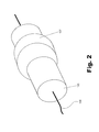
- Fig. 2 is a perspective view of a pass-through for a capillary seal according to one embodiment of the present invention.
- Fig. 3 a cut-away view of a capillary seal according to one embodiment of the present invention.
- Fig. 4 is a flowchart illustrating the operation of the system illustrated in Fig. 1 according to an embodiment of the present invention.
- a capillary seal is defined as the separation of two or more environments or chambers, typically at different pressures, using the wetting and surface tension properties of a liquid to establish a seal between the environments that would otherwise equalize.
- a capillary seal prevents the gases and heat necessary for the power producing reaction from escaping from the interior of a given reaction chamber
- the fuel cell applications of the present invention include, but are not limited to, solid oxide fuel cells (SOFC), alkali fuel cells (AFC), phosphoric acid fuel cells (PAFC), and molten carbonate fuel cells (MCFC).
- SOFC solid oxide fuel cells
- AFC alkali fuel cells
- PAFC phosphoric acid fuel cells
- MCFC molten carbonate fuel cells
- the present invention is particularly applicable to a SOFC. Therefore, the example of a SOFC is used herein to better describe a few of many possible embodiments of the present invention. An overview of a standard SOFC is provided preparatory to a description of the present invention.
- An SOFC uses a hard ceramic electrolyte and typically operates at temperatures up to about 1,000 degrees C (about 1,800 degrees F).
- the electrolyte is a specially treated high density non-porous material that conducts only negatively charged ions.
- a mixture of zirconium oxide and Yttrium oxide is typically used to form a crystal lattice that becomes the high density non-porous electrolyte.
- Other oxide combinations have also been used as electrolytes.
- the solid electrolyte is coated on both sides with specialized porous electrode materials.
- the specialized porous materials act as a catalyst to facilitate an energy-producing reaction between oxygen and various fuels.
- the electrolyte is incorporated into an anode of the fuel cell.
- the anode is the negative post of the fuel cell.
- oxygen ions (with a negative charge) migrate through the crystal lattice.
- a fuel containing hydrogen usually propane or butane
- a flow of negatively charged oxygen ions moves across the electrolyte to oxidize the fuel.
- electrons are freed that are conducted by the anode as a current that can be used in an external circuit.
- the anode needs to be able to disperse the fuel gas as evenly as possible over the surface of the catalyst.
- the oxygen is supplied, usually from air, at the cathode.
- the cathode is the positive post of the fuel cell and similarly, is designed to evenly distribute oxygen (usually air) to the surface of a catalyst.
- Electrons generated at the anode travel through an external load to the cathode, completing the circuit and supplying electric power along the way. Power generation efficiencies of SOFC's can range up to about 60 percent.
- the SOFC consists of an array of tubes.
- Another variation includes a more conventional stack of disks.
- the reactor (10) includes and is housed within a burn chamber (100).
- the burn chamber (100) is preferably designed to contain gases, and other reactive elements used by the SOFC to generate power.
- the burn chamber (100) of an SOFC is commonly constructed using metal or ceramic materials that are unaffected by temperatures ranging from 400 to 1000 C.
- a seal (110) is needed between the interior of the burn chamber (100) and the exterior environment.
- the seal (110) between the interior of the burn chamber (100) and the exterior contains several elements.
- the term "outlet" (111) will refer to the opening through the burn chamber (100) wall in which the seal elements are disposed.
- the term "seal” (110) will refer to the combination of elements that interface between the interior and exterior of the burn chamber (100) preventing heat and reactants inside the burn chamber (100) from escaping through the outlet (111).
- the SOFC preferably includes a number of disks or tubes located within the burn chamber (100) in which the power-producing reaction of the fuel cell is conducted.
- the SOFC disks are stacked forming a fuel cell array or stack (101).
- the fuel cells are arranged in a stack (101) in order to easily distribute the fuel cell reactants and collect the output of each fuel cell.
- An electrical bus (102) is preferably arranged on or near the SOFC stack (101) allowing the power produced in the individual disks or tubes of the fuel cell stack (101) to be collected.
- the output from each disk or tube within the fuel cell is connected to the electrical bus (102).
- the power generated in the stack (101) is then transferred out of the burn chamber (100), preferably on a single conductor (104), connected to the electrical bus (102).
- the conductor (104) may be any conductive material that allows the current produced by the fuel cell stack (101) to be transferred out of the burn chamber (100) through the seal (110). In some embodiments, this conductor (104) will simply be a wire or cable and will accordingly be referred to as a "wire” hereafter. As stated above, the wire (104) connects to the electrical bus (102) and is preferably sufficient to carry all of the power generated by the fuel cell stack (101). The wire (104) runs from the SOFC stack (101) through the seal (110) to the exterior of the burn chamber (100). Outside the SOFC (10), the wire (104) may be connected to a load, e.g., a device requiring electrical power. The wire (104) thus provides power from the fuel cell (10) to that load.
- a load e.g., a device requiring electrical power.
- the wire (104) passes between the interior and exterior of the seal (110) by means of a non-conductive pass-through (105) which is part of the seal (110).
- the pass-through (105) is preferably constructed using a non-conductive material to prevent the wire (100) from shorting with the material of the burn chamber (100) or the SOFC stack (101) which is typically conductive.
- the pass-through (105) may be made from any heat-tolerant non-conductive material but is preferably a ceramic material able to withstand the high temperatures of the burn chamber (100) and the power transfer wire (104).
- the pass-through (105) may have a stop or retention shoulder (107) that functions to seat the pass-through (105) in the outlet (111) of the burn chamber (100).
- the outlet (111) preferably includes an annular groove (112) on the exterior of the burn chamber (100) to receive the retention shoulder (107).
- the retention shoulder may be a separate element used in combination with the pass-through (105) or may be formed as an integral part of the pass-through (105).
- the retention shoulder (107) is preferably held in the groove (112) with a retaining cap (105a).
- the retention shoulder (107) may also secure the pass-through (105) during the expansion and contraction process of the SOFC reactor (10) elements as the SOFC stack (101) heats and cools.
- the burn chamber (100) wall and the pass-through (105) are preferably sized such that there is a gap between the two in the outlet (111).
- the gap preferably allows elements in the seal (110) to expand according the CTE of each without causing mechanical stress or excessive gap size.
- the gap is preferably filled with an expansive adhesion material (103).
- the adhesion material (103) may include a metal or metal alloy that may be used to liquidly seal the gap between the burn chamber (100) and the pass-through (105) as the temperature in the SOFC reactor (10) increases.
- the adhesion material (103) is used to maintain a capillary seal as previously described.
- a preferred adhesion material (103) in embodiments of the present invention is solder.
- Solder (103) is generally a non-ferrous filler metal or metal alloy used to join two wettable (or solder compatible) base materials each of which commonly has a melting point above that of the solder (103). Such materials may include, but are not limited to, tin, lead, and various precious metals as well as alloys of these.
- the solder (103) has a melting point lower than the operational temperature of the SOFC stack (101) or expected burn chamber (100) temperature, a high vapor pressure, and will be non-oxidizing.
- the gap filled with low melting point solder (103) will be heated causing the solder (103) to melt forming a liquid capillary seal between the burn chamber (100) wall and the pass-through (105).
- the melting temperature of the solder (103) allows the liquid capillary seal to conform as the elements within the seal undergo extensive expansion or contraction due to temperature changes within the SOFC reactor (10).
- the solder seal (103) allows the materials used in the burn chamber (100) and the seal (110) to have thermal expansion coefficients that are not identically matched. This allows for substantially more choices for the materials used while improving seal functionality.
- the capillary seal formed by the solder (103) allows the varying pressures between the interior and exterior of the burn chamber (100) to be maintained by sealing the gap around the pass-through (105).
- the capillary seal may be most useful for low-pressure applications without disrupting the seal functionality.
- the burn chamber (100) and the pass-through (105) preferably have highly wettable surfaces.
- wettability is the property of a material that describes the ability of a solder (103) or similar filler material to adhere to its surface. A highly wettable material allows solder (103) to securely and easily adhere to its surface.
- a seed layer is a thin deposition of a material that is high wettable. This allows a material or element with a low wettability to have high wettability properties on portions that have the deposited seed layer.
- the burn chamber (100) and the pass-through (105) preferably have a seed layer deposited on the portion 'of each surface exposed to the gap and solder (103) increasing the wettability of each such surface
- the temperature within the burn chamber (100) will increase significantly.
- the increase in temperature may be sufficiently high such that the elements shown in Fig. 1 expand significantly.
- each element expands is specific to each component and the materials) from which it is constructed. It is important to note that thermal expansion occurs in all dimensions and therefore the aforementioned gap and solder (103) can effectively reduce mechanical stress and prevent blow out of the seal without the level of CTE matching that has been required in the past.
- Using the solder-filled gap (103) allows the materials used in the seal (110) to expand and contract with minimal mechanical stress due to the low yield point of the solder material as compared to burn chamber and pass through (105) material yield points.
- Some variables that affect the amount of pressure that the burn chamber (100) may withstand before the capillary seal is compromised and the solder (103) is bypassed as the pressure equalizes include: pass-through (105) radius, temperature, gap width, surface tension of the solder (103), wettability of the surfaces, contact angle of the wetting surface with the solder (103), and various other factors. It is important to note that the type of solder (103) necessary to insure a proper seal within the burn chamber (100) and outlet will be chosen according to the aforementioned variables, individual application, and pressure needs.
- the sealing process will preferably reverse itself.
- the solder (103) remains a liquid and continues to conform to the shape of the gap until the solidification temperature of the solder is reached.
- the solder (103) solidifies, it seals the gap between the pass-through (105) and the burn chamber (100) with hardened solder. This cooling and reverse sealing process continues until the SOFC reactor (10) reaches an ambient or stand-by temperature.
- Fig. 2 illustrates a different view of the pass-through (105) interface of Fig. 1, including the retention shoulder (107) and power conduction wire (104). It is important to note that a retention shoulder (107) is not necessary for the proper operation of the pass-through (105). However, in the present embodiment the retention shoulder (107) can facilitate assembly and make the pass-through (105) more stable.
- the wire (104) may be centered in the non-conductive pass-through (105).
- the non-conductive pass-through (105) prevents the wire (104) from shorting with the typically conductive burn chamber (not shown).
- the retention shoulder (107) illustrates one of many possible forms of retention for the pass-through (105).
- the pass-through shoulder (107) can prevent fluctuating temperatures from dislodging the pass-through (105) from the burn chamber (100) and provide mechanical limits for preventing excessive motion in the axial direction (parallel to the wire) of the pass-through (105) during expansion or other shock to the elements shown in Fig. 2.
- the burn chamber and retention cap provide the mechanical limits on opposing sides of the retention shoulder (107).
- Fig. 3 shows a capillary seal according to another embodiment of the present invention.
- Fig. 3 shows a cut-away view of a burn chamber (100) wall outlet and a seal (110a).
- the seal (110a) includes a pass-through (106) and an expansive adhesion material, e.g., solder (103), filling the gap between the pass-through (106) and the interior of an opening (115) in the burn chamber (100).
- the non-conductive pass-through is an hourglass shaped pass-through or self-retaining pass-through (106).
- the opening (115) in the burn chamber (100) that receives the pass-through (106) has a corresponding shape as shown in Fig. 3.
- the self-retaining pass-through (106) may eliminate the need for a shoulder on the pass-through as described above in the embodiment illustrated in Fig. 1.
- the burn chamber (100) outlet (115) through which the self-retaining pass-through (106) passes is reshaped to accommodate the self-retaining pass-through (106).
- the gap between the pass-through (106) and the interior of the opening (115) is filled with solder (103) or like material.
- the self-retaining pass-through (106) and burn chamber (100) can expand in all directions.
- the shape of the self-retaining pass-through (106) and corresponding burn chamber opening (115) can reduce stress that would otherwise be caused by expansion in all directions of the pass-through (106) and burn chamber wall (100).
- the shape of the self-retaining pass-through (106) can essentially perform the same function as the previously described pass-through retention shoulder by limiting the movement of the self-retaining pass-through (106) in the opening (115) despite expansion or other motion. As the elements shown in Fig. 3 expand the gap width between the pass-through (106) and the wall (100) will stay approximately constant. This is due to expansion of the pass-through (106) in an axial, as well as a radial direction.
- Fig. 4 is a flow chart illustrating operation of the embodiments of the heat-tolerant capillary sealing system illustrated in Fig. 1 according to principles of the present invention.
- the process begins when the SOFC reactor is started (140). At this point, the required fuel is released within the burn chamber and the elements in and around the SOFC reactor begin to heat up (141) to reach the optimal power production temperature.
- the solder would first yield plastically and then ultimately begin to melt in the gap between the pass-through and the burn chamber (142). At the melting point of the solder, the solder will liquefy adhering to the seeded surface of the pass-through and burn chamber to form a liquid capillary seal (143).
- the temperature continues to rise within the burn chamber to reach the ideal power generation temperature of the SOFC reactor.
- the elements in the SOFC reactor expand in accordance with their individual CTE (144).
- the elements in the burn chamber and outlet may or may not have similar CTE's.
- the elements are somewhat matched so that the gap between the pass-through elements and the burn chamber wall does not become excessively large allowing blow by in the solder filled gap, or excessively small or non-existent causing the expulsion of the solder from the gap or worse creating mechanical stress between the elements.
- the liquefied solder conforms to seal the expanding or contracting gap size between the pass-through and the burn chamber (145).
- the SOFC reactor reaches the operating temperature (146) without excessive expansion of the seal elements.
- the capillary seal formed by the solder preferably prevents the escape of all heat, gases, and other reactive elements required in the burn chamber (147) for efficient SOFC power production.
- the SOFC reactor is turned off, the process shown in Fig. 4 is preferably reversed, i.e., the SOFC reactor cools and the solder eventually solidifies sealing the gap between the burn chamber wall and the pass-through in the 'cool off process.
Landscapes
- Engineering & Computer Science (AREA)
- Chemical & Material Sciences (AREA)
- Combustion & Propulsion (AREA)
- Mechanical Engineering (AREA)
- General Engineering & Computer Science (AREA)
- Fuel Cell (AREA)
Applications Claiming Priority (2)
| Application Number | Priority Date | Filing Date | Title |
|---|---|---|---|
| US10/245,406 US7604240B2 (en) | 2002-09-16 | 2002-09-16 | Capillary seal for a burn chamber |
| US245406 | 2002-09-16 |
Publications (3)
| Publication Number | Publication Date |
|---|---|
| EP1398568A2 true EP1398568A2 (de) | 2004-03-17 |
| EP1398568A3 EP1398568A3 (de) | 2004-03-31 |
| EP1398568B1 EP1398568B1 (de) | 2007-11-14 |
Family
ID=31887836
Family Applications (1)
| Application Number | Title | Priority Date | Filing Date |
|---|---|---|---|
| EP03255262A Expired - Lifetime EP1398568B1 (de) | 2002-09-16 | 2003-08-26 | Kapillardichtung für eine Brennkammer |
Country Status (7)
| Country | Link |
|---|---|
| US (1) | US7604240B2 (de) |
| EP (1) | EP1398568B1 (de) |
| JP (1) | JP3990662B2 (de) |
| KR (1) | KR20040024843A (de) |
| CA (1) | CA2438512A1 (de) |
| DE (1) | DE60317424T2 (de) |
| TW (1) | TWI247866B (de) |
Cited By (1)
| Publication number | Priority date | Publication date | Assignee | Title |
|---|---|---|---|---|
| EP1591725A3 (de) * | 2004-04-30 | 2014-03-05 | Siemens Aktiengesellschaft | Heissgas-Dichtung |
Families Citing this family (3)
| Publication number | Priority date | Publication date | Assignee | Title |
|---|---|---|---|---|
| GB2418478A (en) * | 2004-09-24 | 2006-03-29 | Ti Group Automotive Sys Ltd | A heat exchanger |
| US8263272B2 (en) | 2004-11-09 | 2012-09-11 | Dai Nippon Printing Co., Ltd. | Cogeneration system using fuel cell |
| WO2013173578A2 (en) * | 2012-05-18 | 2013-11-21 | Rave N.P., Inc. | Contamination removal apparatus and method |
Family Cites Families (17)
| Publication number | Priority date | Publication date | Assignee | Title |
|---|---|---|---|---|
| US2223031A (en) * | 1935-12-19 | 1940-11-26 | Electrons Inc | Method of evacuating a vessel and making a vitreous seal |
| DE1227295B (de) | 1960-09-06 | 1966-10-20 | Glaverbel | Wellendichtung |
| US3857679A (en) | 1973-02-05 | 1974-12-31 | Univ Southern California | Crystal grower |
| EP0138292B1 (de) | 1983-08-06 | 1987-10-14 | Sumitomo Electric Industries Limited | Vorrichtung zur Züchtung von Einkristallen |
| DE3472577D1 (en) | 1983-08-31 | 1988-08-11 | Japan Res Dev Corp | Apparatus for growing single crystals of dissociative compounds |
| JPS60112695A (ja) | 1983-11-22 | 1985-06-19 | Sumitomo Electric Ind Ltd | 化合物単結晶の引上方法 |
| US4708431A (en) * | 1984-01-20 | 1987-11-24 | Hughes Aircraft Company | Fiber optic solderable bulkhead fitting |
| DE3527397A1 (de) * | 1985-07-31 | 1987-02-05 | Strahlen Umweltforsch Gmbh | Verfahren und einrichtung zur nachpruefbaren freisetzung von gasen |
| US5208509A (en) * | 1988-05-13 | 1993-05-04 | Gte Products Corporation | Arc tube for high pressure metal vapor discharge lamp |
| US5155336A (en) * | 1990-01-19 | 1992-10-13 | Applied Materials, Inc. | Rapid thermal heating apparatus and method |
| US6016383A (en) * | 1990-01-19 | 2000-01-18 | Applied Materials, Inc. | Rapid thermal heating apparatus and method including an infrared camera to measure substrate temperature |
| DE9207816U1 (de) * | 1992-06-10 | 1992-08-20 | Patent-Treuhand-Gesellschaft für elektrische Glühlampen mbH, 8000 München | Hochdruckentladungslampe |
| DE4242123A1 (de) * | 1992-12-14 | 1994-06-16 | Patent Treuhand Ges Fuer Elektrische Gluehlampen Mbh | Hochdruckentladungslampe mit einem keramischen Entladungsgefäß |
| EP0609477B1 (de) * | 1993-02-05 | 1999-05-06 | Patent-Treuhand-Gesellschaft für elektrische Glühlampen mbH | Keramisches Entladungsgefäss für Hochdruckentladungslampe und Herstellungsverfahren derselben und damit verbundene Dichtungsmaterialien |
| ZA955492B (en) | 1994-07-18 | 1996-02-13 | Methanol Casale Sa | Catalyst-seal support device in particular for exothermic heterogeneous catalytic synthesis reactors |
| SE506059C2 (sv) * | 1996-02-28 | 1997-11-03 | Electrolux Ab | Anordning vid en förångare |
| US6486054B1 (en) * | 2002-01-28 | 2002-11-26 | Taiwan Semiconductor Manufacturing Company | Method to achieve robust solder bump height |
-
2002
- 2002-09-16 US US10/245,406 patent/US7604240B2/en not_active Expired - Fee Related
-
2003
- 2003-07-30 TW TW092120804A patent/TWI247866B/zh not_active IP Right Cessation
- 2003-08-26 DE DE60317424T patent/DE60317424T2/de not_active Expired - Lifetime
- 2003-08-26 EP EP03255262A patent/EP1398568B1/de not_active Expired - Lifetime
- 2003-08-27 CA CA002438512A patent/CA2438512A1/en not_active Abandoned
- 2003-09-15 KR KR1020030063740A patent/KR20040024843A/ko not_active Withdrawn
- 2003-09-16 JP JP2003322883A patent/JP3990662B2/ja not_active Expired - Fee Related
Cited By (2)
| Publication number | Priority date | Publication date | Assignee | Title |
|---|---|---|---|---|
| EP1591725A3 (de) * | 2004-04-30 | 2014-03-05 | Siemens Aktiengesellschaft | Heissgas-Dichtung |
| US8695989B2 (en) | 2004-04-30 | 2014-04-15 | Siemens Aktiengesellschaft | Hot gas seal |
Also Published As
| Publication number | Publication date |
|---|---|
| US20040053103A1 (en) | 2004-03-18 |
| JP2004111392A (ja) | 2004-04-08 |
| EP1398568B1 (de) | 2007-11-14 |
| KR20040024843A (ko) | 2004-03-22 |
| US7604240B2 (en) | 2009-10-20 |
| CA2438512A1 (en) | 2004-03-16 |
| DE60317424T2 (de) | 2008-09-11 |
| EP1398568A3 (de) | 2004-03-31 |
| TWI247866B (en) | 2006-01-21 |
| JP3990662B2 (ja) | 2007-10-17 |
| DE60317424D1 (de) | 2007-12-27 |
| TW200408786A (en) | 2004-06-01 |
Similar Documents
| Publication | Publication Date | Title |
|---|---|---|
| EP1493202B1 (de) | Elektrochemischer lithiumgenerator mit mindestens einer bipolarelektrode mit leitfähigen aluminium- oder aluminiumlegierungssubstraten | |
| CN103155234B (zh) | 具有双金属电极的碱金属离子电池组 | |
| US9076996B2 (en) | Liquid metal alloy energy storage device | |
| US4770955A (en) | Solid electrolyte fuel cell and assembly | |
| RU2357331C2 (ru) | Установка с твердооксидным топливным элементом | |
| US3959013A (en) | Cathode cell casing portion, a cell casing, and a hermetically sealed sodium-sulfur cell | |
| WO2015063588A2 (en) | Self healing liquid/solid state battery | |
| JP6670247B2 (ja) | 電気化学的エネルギー貯蔵装置並びにそれの作動方法 | |
| JP2002025515A (ja) | 不整合圧力下のガラス−対−金属シール | |
| EP1398568B1 (de) | Kapillardichtung für eine Brennkammer | |
| US4084040A (en) | Cell casing and a hermetically sealed sodium-sulfur cell | |
| US12034189B2 (en) | Fuel cell system glow plug and method of forming same | |
| US11824232B2 (en) | Internal light off mechanism for solid oxide fuel cell system startup using a spark ignitor | |
| JP2601911B2 (ja) | 円筒型固体電解質型燃料電池 | |
| EP3547428A1 (de) | Elektrochemische reaktionseinheit, zellenstapel für elektrochemische reaktion und verfahren zur herstellung einer elektrochemischen reaktionseinheit | |
| CN219328119U (zh) | 用于固体氧化物燃料电池系统的电热塞及固体氧化物燃料电池系统 | |
| WO2022168117A1 (en) | Method for the manufacture of lower capacity elliptic cylindrical lithium ion cells with low internal resistance | |
| KR20030052106A (ko) | 고체 산화물 연료 전지용 금속간 화합물 접속자 | |
| JP6344548B2 (ja) | 固体酸化物型燃料電池装置の製造方法 | |
| JPH11307109A (ja) | 円筒型固体電解質燃料電池およびその製造方法 | |
| Whittingham | Fast ion transport materials and batteries | |
| JPH0773059B2 (ja) | 溶融炭酸塩型燃料電池 | |
| JPH07122284A (ja) | 平板型固体電解質燃料電池用ガスシール構造 | |
| JP2015170496A (ja) | 固体酸化物型燃料電池装置及びその製造方法 |
Legal Events
| Date | Code | Title | Description |
|---|---|---|---|
| PUAI | Public reference made under article 153(3) epc to a published international application that has entered the european phase |
Free format text: ORIGINAL CODE: 0009012 |
|
| PUAL | Search report despatched |
Free format text: ORIGINAL CODE: 0009013 |
|
| AK | Designated contracting states |
Kind code of ref document: A2 Designated state(s): AT BE BG CH CY CZ DE DK EE ES FI FR GB GR HU IE IT LI LU MC NL PT RO SE SI SK TR |
|
| AX | Request for extension of the european patent |
Extension state: AL LT LV MK |
|
| AK | Designated contracting states |
Kind code of ref document: A3 Designated state(s): AT BE BG CH CY CZ DE DK EE ES FI FR GB GR HU IE IT LI LU MC NL PT RO SE SI SK TR |
|
| AX | Request for extension of the european patent |
Extension state: AL LT LV MK |
|
| RIC1 | Information provided on ipc code assigned before grant |
Ipc: 7F 16J 15/40 B Ipc: 7F 23M 11/02 A Ipc: 7H 01B 17/58 B |
|
| 17P | Request for examination filed |
Effective date: 20040910 |
|
| AKX | Designation fees paid |
Designated state(s): DE FR GB NL |
|
| GRAP | Despatch of communication of intention to grant a patent |
Free format text: ORIGINAL CODE: EPIDOSNIGR1 |
|
| RIN1 | Information on inventor provided before grant (corrected) |
Inventor name: ARTHUR, ALAN R. |
|
| GRAS | Grant fee paid |
Free format text: ORIGINAL CODE: EPIDOSNIGR3 |
|
| GRAA | (expected) grant |
Free format text: ORIGINAL CODE: 0009210 |
|
| AK | Designated contracting states |
Kind code of ref document: B1 Designated state(s): DE FR GB NL |
|
| REG | Reference to a national code |
Ref country code: GB Ref legal event code: FG4D |
|
| REF | Corresponds to: |
Ref document number: 60317424 Country of ref document: DE Date of ref document: 20071227 Kind code of ref document: P |
|
| PG25 | Lapsed in a contracting state [announced via postgrant information from national office to epo] |
Ref country code: NL Free format text: LAPSE BECAUSE OF FAILURE TO SUBMIT A TRANSLATION OF THE DESCRIPTION OR TO PAY THE FEE WITHIN THE PRESCRIBED TIME-LIMIT Effective date: 20071114 |
|
| NLV1 | Nl: lapsed or annulled due to failure to fulfill the requirements of art. 29p and 29m of the patents act | ||
| ET | Fr: translation filed | ||
| PLBE | No opposition filed within time limit |
Free format text: ORIGINAL CODE: 0009261 |
|
| STAA | Information on the status of an ep patent application or granted ep patent |
Free format text: STATUS: NO OPPOSITION FILED WITHIN TIME LIMIT |
|
| 26N | No opposition filed |
Effective date: 20080815 |
|
| PGFP | Annual fee paid to national office [announced via postgrant information from national office to epo] |
Ref country code: FR Payment date: 20080818 Year of fee payment: 6 |
|
| PGFP | Annual fee paid to national office [announced via postgrant information from national office to epo] |
Ref country code: GB Payment date: 20090825 Year of fee payment: 7 |
|
| PGFP | Annual fee paid to national office [announced via postgrant information from national office to epo] |
Ref country code: DE Payment date: 20090827 Year of fee payment: 7 |
|
| REG | Reference to a national code |
Ref country code: FR Ref legal event code: ST Effective date: 20100430 |
|
| PG25 | Lapsed in a contracting state [announced via postgrant information from national office to epo] |
Ref country code: FR Free format text: LAPSE BECAUSE OF NON-PAYMENT OF DUE FEES Effective date: 20090831 |
|
| GBPC | Gb: european patent ceased through non-payment of renewal fee |
Effective date: 20100826 |
|
| REG | Reference to a national code |
Ref country code: DE Ref legal event code: R119 Ref document number: 60317424 Country of ref document: DE Effective date: 20110301 |
|
| PG25 | Lapsed in a contracting state [announced via postgrant information from national office to epo] |
Ref country code: DE Free format text: LAPSE BECAUSE OF NON-PAYMENT OF DUE FEES Effective date: 20110301 |
|
| PG25 | Lapsed in a contracting state [announced via postgrant information from national office to epo] |
Ref country code: GB Free format text: LAPSE BECAUSE OF NON-PAYMENT OF DUE FEES Effective date: 20100826 |