EP1399078B1 - Ensemble permettant de stabiliser des corps vertebraux de la colonne vertebrale - Google Patents
Ensemble permettant de stabiliser des corps vertebraux de la colonne vertebrale Download PDFInfo
- Publication number
- EP1399078B1 EP1399078B1 EP02735616A EP02735616A EP1399078B1 EP 1399078 B1 EP1399078 B1 EP 1399078B1 EP 02735616 A EP02735616 A EP 02735616A EP 02735616 A EP02735616 A EP 02735616A EP 1399078 B1 EP1399078 B1 EP 1399078B1
- Authority
- EP
- European Patent Office
- Prior art keywords
- spring member
- assembly according
- range
- straight portions
- substantially straight
- Prior art date
- Legal status (The legal status is an assumption and is not a legal conclusion. Google has not performed a legal analysis and makes no representation as to the accuracy of the status listed.)
- Expired - Lifetime
Links
Images


Classifications
-
- A—HUMAN NECESSITIES
- A61—MEDICAL OR VETERINARY SCIENCE; HYGIENE
- A61B—DIAGNOSIS; SURGERY; IDENTIFICATION
- A61B17/00—Surgical instruments, devices or methods
- A61B17/56—Surgical instruments or methods for treatment of bones or joints; Devices specially adapted therefor
- A61B17/58—Surgical instruments or methods for treatment of bones or joints; Devices specially adapted therefor for osteosynthesis, e.g. bone plates, screws or setting implements
- A61B17/68—Internal fixation devices, including fasteners and spinal fixators, even if a part thereof projects from the skin
- A61B17/70—Spinal positioners or stabilisers, e.g. stabilisers comprising fluid filler in an implant
- A61B17/7001—Screws or hooks combined with longitudinal elements which do not contact vertebrae
- A61B17/7002—Longitudinal elements, e.g. rods
- A61B17/7019—Longitudinal elements having flexible parts, or parts connected together, such that after implantation the elements can move relative to each other
- A61B17/7026—Longitudinal elements having flexible parts, or parts connected together, such that after implantation the elements can move relative to each other with a part that is flexible due to its form
-
- A—HUMAN NECESSITIES
- A61—MEDICAL OR VETERINARY SCIENCE; HYGIENE
- A61B—DIAGNOSIS; SURGERY; IDENTIFICATION
- A61B17/00—Surgical instruments, devices or methods
- A61B17/56—Surgical instruments or methods for treatment of bones or joints; Devices specially adapted therefor
- A61B17/58—Surgical instruments or methods for treatment of bones or joints; Devices specially adapted therefor for osteosynthesis, e.g. bone plates, screws or setting implements
- A61B17/68—Internal fixation devices, including fasteners and spinal fixators, even if a part thereof projects from the skin
- A61B17/70—Spinal positioners or stabilisers, e.g. stabilisers comprising fluid filler in an implant
- A61B17/7001—Screws or hooks combined with longitudinal elements which do not contact vertebrae
- A61B17/7002—Longitudinal elements, e.g. rods
- A61B17/7011—Longitudinal element being non-straight, e.g. curved, angled or branched
Definitions
- the invention relates to an assembly for the stabilisation of vertebral bodies of the spine of the kind which is secured to the adjacent vertebral bodies by pedicle screws, and in particular although not exclusively to such an assembly for stabilisation of two adjacent vertebral bodies.
- the lumbo-sacral region of the human spine consists of five lumbar vertebrae located above the large triangular bone called the sacrum. Between adjacent lumbar vertebrae are inter-vertebral discs (IVD) which have a complex structure, with a central jelly like nucleus pulposus and a peripheral rim of tough fibrous layers, the annulus fibrosus. Each lumbar vertebra is made up of a vertebral body, with upper and lower end plates, which contact the IVD's, and facet joints located posteriorlly. Movement in the lumbo-sacral spine occurs in the IVD's at the front and at the facet joints at the rear.
- IVD inter-vertebral discs
- the IVD's and the facet joints provide stability of the motion segment between adjacent vertebra. However, they also transfer load from one vertebra to the next, and it is estimated that the IVD bears approximately 80% of the load and the pair of facet joints at the rear bear approximately 20% of the load.
- a normal IVD can distribute the load uniformly across the surface of the end plate of the vertebral body. However, when the IVD and/or the facet joints are damaged or degenerate this can lead to instability of the motion segment between adjacent vertebra and commonly to low back pain. It is considered that the pain can be caused by abnormal movement, and/or by abnormal distribution of load across the end plates of the vertebrae.
- the Graf ligament system consists of a fabric ligament secured across pedicle screws located in the adjacent vertebrae. Typically two such ligaments are located across each motion segment, one to each side on the rear of the spine.
- This system creates lordosis (curvature of the spine, convex forwards) and restricts the movement of the motion segment between the vertebrae concerned, but it also increases the load at the posterior part of the IVD.
- lordosis curvature of the spine, convex forwards
- the other soft stabilisation system which is in the process of development is a fulcrum assisted soft stabilisation system (FASS) which is described in International patent application WO-A-01/45576.
- FSS fulcrum assisted soft stabilisation system
- the compressing effect of the ligament found in the Graf ligament system is converted into a distraction effect by the use of a fulcrum bridging between the pedicle screws, and located between the ligament and the spine.
- This system can unload the IVD in forward flexion but not in extension.
- the IVD is loaded both in flexion and extension and the facet joints are specifically loaded in extension.
- this system also is expected to suffer from disadvantages.
- an assembly for the stabilisation of vertebral bodies of the spine comprising a pair of pedicle screws each having a threaded shaft with a tapering first end for introduction into a vertebral body and a head portion with a second end, characterised in that it further comprises:
- the substantially curvilinear central portion of the spring member typically has a radius of curvature in the range 3 to 17 mm or in the.range 5 to 15 mm.
- the substantially straight portions of the spring member may be at an angle to each other in the range 0 to 180 degrees, or 90 to 180 degrees. When the straight portions are at 180 degrees they are substantially coaxial. When the substantially straight portions of the spring member are at 0 degrees they are parallel.
- the spring member is formed from wire.
- the spring member may have a diameter in the range 1 to 6 mm, or in the range 2 to 5 mm.
- the spring member may have substantially straight portions of greater cross sectional area than that of the substantially curvilinear portion.
- the assembly may have a pair of sleeves, one on each of the substantially straight portions, to effectively increase the external diameter of at least a part of each of the substantially straight portions.
- Such sleeves may have external diameters in the range 5mm to 8mm.
- the spring member may be round in cross section, or alternatively may be square or rectangular in cross section.
- the spring member is preferably formed from titanium or stainless steel.
- the threaded shaft portions of the pedicle screws may have lengths in the range 30 to 60 mm, or in the range 35 to 55 mm.
- the pedicle screws are formed from titanium.
- the assembly may be for stabilisation of two adjacent vertebral bodies of the spine, i.e. one motion segment.
- the spring member has a length in the range 20 to 65 mm, but it may be in the range 25 to 60 mm.
- the assembly may have a spring member which is specifically adapted for stabilisation of three vertebral bodies of the spine, that is two motion segments.
- the spring member typically has a length in the range 50-110mm, but it may be in the range 60-100mm.
- Figures 1-6 and 8-9 do not depict the spring member according to the invention but they serve for elucidation of the technical aspects thereof.
- an assembly 10 for the stabilisation of two adjacent vertebral bodies 12, 14 of the spine is illustrated schematically.
- the vertebral bodies 12, 14 are separated by an inter-vertebral disc 16 which has a nucleus pulposus 16a and a fibrous outer-annulus, called the annulus fibrosus, 16b.
- the facet joints have been omitted from the posterior of the vertebral bodies 12, 14.
- the assembly 10 is fixed to the posterior of the vertebral bodies 12, 14.
- the assembly 10 comprises a spring member 18 which has a central substantially curvilinear portion 18a, which in this embodiment is C-shaped, and substantially straight portions 18 b extending outward therefrom.
- the straight portions 18 b and curvilinear portion 18 a are joined by reverse curvature portions 18 c .
- the assembly 10 further comprises a pair of pedicle screws 20 each of which comprises a threaded shaft portion 20 a with a tapering first end 20 b and a head portion 20 c with a second end 20 d .
- the assembly 10 is illustrated in position secured to the posterior of a pair of adjacent vertebral bodies 12, 14 with the threaded shaft portions 20 a of the pedicle screws 20 inserted into the vertebral bodes 12, 14.
- the spring member 18 is secured to the heads 20 c of each of the pedical screws 20 by a fixation mechanism as appropriate.
- An example of a fixation mechanism will be described later, although any appropriate mechanism may be used.
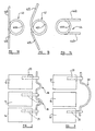
- Figure 2 a shows the spring member 18 from Figure 1.
- the substantially straight portions 18 b are coaxial, i.e. at an angle of 180° to each other, and the substantially curvilinear portion 18a is C-shaped and approximately a semi-circle.
- the reverse curvature portions 18 c are of small radius and approximate to right angles.
- a first alternative spring member 22 is illustrated in which the substantially straight portions 22 b are at an angle to each other of approximately 150°, and the substantially curvilinear portion 22 a is again C-shaped and approximately a semi-circle.
- the substantially straight portions 22 b and the substantially curvilinear portion 22 a are joined by reverse curvature portions 22 c which in this spring member 22 are of relatively small radius, but not as small as in the embodiment above.
- FIG. 2 c a third embodiment of a spring member 24 is illustrated.
- the spring member 24 again comprises two substantially straight portions 24 b , with a substantially curvilinear portion 24 a therebetween, these portions being joined by reverse curvature portions 24 c which are of a larger radius of curvature than those 22 c in the previous embodiment.
- the substantially straight portions 24 b are again at an angle to each other, this time of approximately 140°.
- the substantially curvilinear portions 18 a , 22 a , and 24 a are all shown as being smooth curves approximating to a semi-circle. However, they could take other forms, such as for examples being smaller arcs of a circle, or indeed not being strictly curvilinear but comprising a plurality of short straight portions.
- the substantially straight portions 18 b , 22 b and 24 b are all shown as being straight, but they could in alternative embodiments be very slightly curved. They will generally be at angles to each other in the range 90 to 180° for embodiments such as these with C-shaped curvilinear central portions 18 a , 22 a and 24 a .
- the spring members 18, 22 and 24 are made from titanium or stainless steel wire, each spring member being bent from a single piece.
- the wire will typically have a diameter in the range 1 to 6mm, but preferably in a range of 2 to 5mm.
- the wire may be round in cross-section or may be of other forms e.g. square, rectangular, or oval in cross section.
- the spring members 18, 22 and 24, which are all designed to be used between adjacent vertebral bodies, have an overall length in the range 20mm to 65mm, but preferably in the range 25mm to 60mm.
- a pair of assemblies 10 according to this invention are shown secured to a pair of adjacent vertebral bodies 12, 14. This is the manner in which the assembly 10 will generally be used, with one assembly 10 applied to either side of the vertebral bodies on the posterior aspect of the spine.
- the head 20 c of the pedicle screw 20 is shown with a particular form. It comprises a slot 30 which provides the dual purpose of accepting the blade of a screw driver for insertion of the pedicle screw 20 into a vertebral body, and for receipt of the substantially straight portions 24 b of the spring member 24.
- the head 20 c further comprises adjacent its second end 20 d , and around the upper part of the slot 30, a threaded portion 32.
- the fixation mechanism 26 further comprises a sleeve member 34 and threaded nut 36, also sleeves 38 which are located on the substantially straight portions 24 b of the spring member 24 before the assembly 10 is put together as shown in Figure 6 b .
- the sleeves 38 effectively increase the outer diameter of the spring member 24 as necessary for use in the fixation mechanism 26.
- the sleeves 38 may typically increase the diameter to somewhere in the range 5mm to 8mm, as appropriate for the pedicle screw being used.
- the substantially straight portions 24 b of the spring member 24 may be formed with a greater diameter than that of the substantially curvilinear portion 24 a , and thus have a greater cross-sectional area than the substantially curvilinear portion 24 a .
- the fixation mechanism 26 is shown assembled in Figure 6 c . Once the screw 20 has been inserted into the vertebral body one substantially straight portion 24 b of the spring member 24, with sleeve 38 in place, is located in the slot 30. The sleeve member 34 is then placed over the head 20 c of the pedicle screw 20, and the nut 36 screwed down onto the threaded portion 32 to retain the spring member 24 in place.
- the fixation mechanism 26 may further include a check nut (not shown), as is known in the prior art, to further secure the mechanism together and to reduce the possibility of it loosening over time.
- fixation mechanism 26 is one example of many options which would be available, and any appropriate fixation mechanism may be used.
- a spring member 40 comprises a substantially curvilinear central portion 40 a in the form of a coil, and two substantially straight portions 40 b extending therefrom at substantially 180° to each other.
- the second, shown in Figure 7 b is a spring member 42 comprising a substantially curvilinear portion 42 a , comprising a coil as for the previous embodiment, with two substantially straight portions 42 b extending therefrom at an angle of approximately 120° to each other.
- the third embodiment shown in Figure 7 c , comprises a spring member 44 having a central substantially curvilinear portion 44 a comprising a coil as previously, and two substantially straight portions 44 b extending therefrom, but this time at approximately 0° to each other and substantially parallel. It will be appreciated that the spring members 40, 42 and 44 are shown unloaded, rather than as they would be after implantation with the patient in a normal rest position, by which time they would be loaded.
- the substantially straight portions 40 b , 42 b and 44 b are substantially coplanar, in that they are as close to coplanar as can be achieved when the substantially curvilinear portions 40 a , 42 a and 44 a comprise coils.
- FIG. 9 One such example, for use across two motion segments, is illustrated in Figure 9 in which three vertebral bodies are shown referenced 12, 14 and 14'.
- a pedicle screw 20 is inserted into the upper most vertebral body 12, and into the lower most vertebral body 14'.
- a spring member 46 substantially of the form of the spring member 18 but of larger dimension, is secured between the two pedicle screws 20.
- Spring member 18 will be longer than embodiments previously described, and may be as long as 110mm or 100mm.
- spring members for use in a particular case will depend on a large number of factors. These will include the sizes of the vertebral bodies, the number of motion segments requiring stabilisation, and the particular condition being treated.
Landscapes
- Health & Medical Sciences (AREA)
- Orthopedic Medicine & Surgery (AREA)
- Life Sciences & Earth Sciences (AREA)
- Neurology (AREA)
- Surgery (AREA)
- Molecular Biology (AREA)
- General Health & Medical Sciences (AREA)
- Biomedical Technology (AREA)
- Heart & Thoracic Surgery (AREA)
- Medical Informatics (AREA)
- Nuclear Medicine, Radiotherapy & Molecular Imaging (AREA)
- Animal Behavior & Ethology (AREA)
- Engineering & Computer Science (AREA)
- Public Health (AREA)
- Veterinary Medicine (AREA)
- Surgical Instruments (AREA)
- Prostheses (AREA)
- Materials For Medical Uses (AREA)
- Massaging Devices (AREA)
- Diaphragms For Electromechanical Transducers (AREA)
- Seats For Vehicles (AREA)
Claims (25)
- Ensemble pour la stabilisation de corps vertébraux de la colonne vertébrale comprenant :caractérisé en ce que la partie centrale sensiblement curviligne (40a, 42a, 44a) de l'élément à ressort est une spire.une paire de vis pédiculaires (20), chacune ayant une tige filetée (20a) avec une première extrémité conique (20b) pour l'introduction dans un corps vertébral, et une partie de tête (20c) avec une seconde extrémité (20d),un élément à ressort (40, 42, 44) ayant des première et seconde extrémités, sensiblement des parties rectilignes (40b, 42b, 44b) adjacentes à chaque extrémité et une partie centrale sensiblement curviligne (40a, 42a, 44a) entre celles-ci, les parties rectilignes (40b, 42b, 44b) et la partie centrale sensiblement curviligne (40a, 42a, 42b) étant sensiblement coplanaires ; etune paire de mécanismes de fixation (26) pour immobiliser les première et seconde extrémités de l'élément à ressort (40, 42, 44) à la paire de vis pédiculaires (20),
- Ensemble selon une quelconque des revendications précédentes,
caractérisé en ce que la partie sensiblement curviligne (40a, 42a, 44a) de l'élément à ressort (40, 42, 44) a un rayon de courbure compris dans la plage entre 3 et 17 mm. - Ensemble selon la revendication 2, caractérisé en ce que la partie centrale sensiblement curviligne (40a, 42a, 44a) de l'élément à ressort (40, 42, 44) a un rayon de courbure compris dans la plage entre 5 et 15 mm.
- Ensemble selon une quelconque des revendications précédentes, caractérisé en ce que les parties sensiblement rectilignes (40b, 42b, 44b) de l'élément à ressort (40, 42, 44) forment l'une par rapport à l'autre un angle compris dans la plage entre 0 et 180°.
- Ensemble selon la revendication 4,
caractérisé en ce que les parties sensiblement rectilignes (40b, 42b, 44b) de l'élément à ressort (40, 42, 44) forment l'une par rapport à l'autre un angle compris dans la plage entre 90 et 180°. - Ensemble selon une quelconque des revendications 1 à 3,
caractérisé en ce que les parties sensiblement rectilignes (40b, 42b, 44b) de l'élément à ressort (40, 42, 44) sont coaxiales l'une par rapport à l'autre. - Ensemble selon une quelconque des revendications 1 à 3,
caractérisé en ce que les parties sensiblement rectilignes (40b, 42b, 44b) de l'élément à ressort (40, 42, 44) sont parallèles l'une par rapport à l'autre. - Ensemble selon une quelconque des revendications précédentes, caractérisé en ce que l'élément à ressort (40, 42, 44) est réalisé à partir d'un fil métallique.
- Ensemble selon une quelconque des revendications précédentes, caractérisé en ce que l'élément à ressort (40, 42, 44) a un diamètre compris dans la plage entre 1 et 6 mm.
- Ensemble selon la revendication 9,
caractérisé en ce que l'élément à ressort (40, 42, 44) a un diamètre compris dans la plage entre 2 et 5 mm. - Ensemble selon une quelconque des revendications précédentes,
caractérisé en ce qu'au moins les portions des parties sensiblement rectilignes (40b, 42b, 44b) adjacentes aux extrémités de l'élément à ressort (40, 42, 44) ont une aire en coupe transversale plus grande que celle de la partie centrale sensiblement curviligne (40a, 42a, 44a). - Ensemble selon une quelconque des revendications 1 à 10, caractérisé en ce qu'il comprend une paire de manchons (38), un sur chacune des parties sensiblement rectilignes (40b, 42b, 44b), pour augmenter efficacement le diamètre externe d'au moins une portion de chacune des parties sensiblement rectilignes (40b, 42b, 44b).
- Ensemble selon la revendication 12,
caractérisé en ce que les manchons (38) ont un diamètre externe compris dans la plage entre 5 mm et 8 mm. - Ensemble selon une quelconque des revendications précédentes,
caractérisé en ce que l'élément à ressort (40, 42, 44) est rond en coupe transversale. - Ensemble selon une quelconque des revendications 1 à 13,
caractérisé en ce que l'élément à ressort (40, 42, 44) est carré ou rectangulaire en coupe transversale. - Ensemble selon une quelconque des revendications précédentes,
caractérisé en ce que l'élément à ressort (40, 42, 44) est réalisé à partir de titane ou d'acier inoxydable. - Ensemble selon une quelconque des revendications précédentes,
caractérisé en ce que les parties à tige filetée (20a) des vis pédiculaires (20) ont des longueurs comprises dans la plage entre 30 et 60 mm. - Ensemble selon la revendication 17,
caractérisé en ce que les parties à tige filetée (20a) des vis pédiculaires (20) ont des longueurs comprises dans la plage entre 35 et 55 mm. - Ensemble selon une quelconque des revendications précédentes,
caractérisé en ce que les vis pédiculaires (20) sont réalisées en titane. - Ensemble selon une quelconque des revendications précédentes,
caractérisé en ce que l'élément à ressort (40, 42, 44) est spécifiquement adapté à la stabilisation de deux corps vertébraux adjacents de la colonne vertébrale, c'est-à-dire un segment de mouvement. - Ensemble selon la revendication 20,
caractérisé en ce que l'élément à ressort (40, 42, 44) a une longueur comprise dans la plage entre 20 et 65 mm. - Ensemble selon la revendication 21,
caractérisé en ce que l'élément à ressort (40, 42, 44) a une longueur comprise dans la plage entre 25 et 60 mm. - Ensemble selon une quelconque des revendications 1 à 19,
caractérisé en ce que l'élément à ressort (40, 42, 44) est spécifiquement adapté à la stabilisation de trois corps vertébraux de la colonne vertébrale, c'est-à-dire deux segments de mouvement. - Ensemble selon la revendication 23,
caractérisé en ce que l'élément à ressort (40, 42, 44) a une longueur comprise dans la plage entre 50-110 mm. - Ensemble selon la revendication 24,
caractérisé en ce que l'élément à ressort (40, 42, 44) a une longueur comprise dans la plage entre 60-100 mm.
Applications Claiming Priority (3)
| Application Number | Priority Date | Filing Date | Title |
|---|---|---|---|
| GBGB0114783.4A GB0114783D0 (en) | 2001-06-16 | 2001-06-16 | A assembly for the stabilisation of vertebral bodies of the spine |
| GB0114783 | 2001-06-16 | ||
| PCT/GB2002/002709 WO2002102259A2 (fr) | 2001-06-16 | 2002-06-17 | Ensemble permettant de stabiliser des corps vertebraux de la colonne vertebrale |
Publications (3)
| Publication Number | Publication Date |
|---|---|
| EP1399078A2 EP1399078A2 (fr) | 2004-03-24 |
| EP1399078B1 true EP1399078B1 (fr) | 2004-12-15 |
| EP1399078B8 EP1399078B8 (fr) | 2005-05-25 |
Family
ID=9916787
Family Applications (1)
| Application Number | Title | Priority Date | Filing Date |
|---|---|---|---|
| EP02735616A Expired - Lifetime EP1399078B8 (fr) | 2001-06-16 | 2002-06-17 | Ensemble permettant de stabiliser des corps vertebraux de la colonne vertebrale |
Country Status (10)
| Country | Link |
|---|---|
| US (1) | US7632292B2 (fr) |
| EP (1) | EP1399078B8 (fr) |
| JP (1) | JP2004528945A (fr) |
| AT (1) | ATE284649T1 (fr) |
| AU (1) | AU2002310625B2 (fr) |
| CA (1) | CA2450933A1 (fr) |
| DE (1) | DE60202289T2 (fr) |
| ES (1) | ES2235045T3 (fr) |
| GB (1) | GB0114783D0 (fr) |
| WO (1) | WO2002102259A2 (fr) |
Cited By (23)
| Publication number | Priority date | Publication date | Assignee | Title |
|---|---|---|---|---|
| US7041136B2 (en) | 2000-11-29 | 2006-05-09 | Facet Solutions, Inc. | Facet joint replacement |
| US7074237B2 (en) | 2000-12-13 | 2006-07-11 | Facet Solutions, Inc. | Multiple facet joint replacement |
| US7090698B2 (en) | 2001-03-02 | 2006-08-15 | Facet Solutions | Method and apparatus for spine joint replacement |
| US7361196B2 (en) | 2005-02-22 | 2008-04-22 | Stryker Spine | Apparatus and method for dynamic vertebral stabilization |
| US7507242B2 (en) | 2004-06-02 | 2009-03-24 | Facet Solutions | Surgical measurement and resection framework |
| US7566345B1 (en) | 2001-03-01 | 2009-07-28 | Facet Solutions, Inc | Prosthesis for the replacement of a posterior element of a vertebra |
| US7588590B2 (en) | 2003-12-10 | 2009-09-15 | Facet Solutions, Inc | Spinal facet implant with spherical implant apposition surface and bone bed and methods of use |
| US7641673B2 (en) | 2000-07-25 | 2010-01-05 | Zimmer Spine, S.A.S. | Flexible linking piece for stabilising the spine |
| US7722647B1 (en) | 2005-03-14 | 2010-05-25 | Facet Solutions, Inc. | Apparatus and method for posterior vertebral stabilization |
| US7758581B2 (en) | 2005-03-28 | 2010-07-20 | Facet Solutions, Inc. | Polyaxial reaming apparatus and method |
| US7935134B2 (en) | 2004-10-20 | 2011-05-03 | Exactech, Inc. | Systems and methods for stabilization of bone structures |
| CN102106750A (zh) * | 2011-02-17 | 2011-06-29 | 上海微创骨科医疗科技有限公司 | 一种脊柱动态连接棒 |
| US7993373B2 (en) | 2005-02-22 | 2011-08-09 | Hoy Robert W | Polyaxial orthopedic fastening apparatus |
| US7998175B2 (en) | 2004-10-20 | 2011-08-16 | The Board Of Trustees Of The Leland Stanford Junior University | Systems and methods for posterior dynamic stabilization of the spine |
| US8025680B2 (en) | 2004-10-20 | 2011-09-27 | Exactech, Inc. | Systems and methods for posterior dynamic stabilization of the spine |
| DE102010041264A1 (de) | 2010-09-23 | 2012-03-29 | Aces Gmbh | Dynamische Stabilisierungseinrichtung für die Wirbelsäule |
| US8206418B2 (en) | 2007-01-10 | 2012-06-26 | Gmedelaware 2 Llc | System and method for facet joint replacement with detachable coupler |
| DE102012202749A1 (de) | 2012-02-22 | 2013-08-22 | Aces Gmbh | Dynamische Knochenverankerungseinrichtung |
| DE102012202750A1 (de) | 2012-02-22 | 2013-08-22 | Aces Gmbh | Dynamische stabilisierungseinrichtung für die wirbelsäule |
| US8562649B2 (en) | 2004-02-17 | 2013-10-22 | Gmedelaware 2 Llc | System and method for multiple level facet joint arthroplasty and fusion |
| US8623059B2 (en) | 2005-10-31 | 2014-01-07 | Stryker Spine | System and method for dynamic vertebral stabilization |
| US8764801B2 (en) | 2005-03-28 | 2014-07-01 | Gmedelaware 2 Llc | Facet joint implant crosslinking apparatus and method |
| US8900273B2 (en) | 2005-02-22 | 2014-12-02 | Gmedelaware 2 Llc | Taper-locking fixation system |
Families Citing this family (191)
| Publication number | Priority date | Publication date | Assignee | Title |
|---|---|---|---|---|
| FR2812185B1 (fr) | 2000-07-25 | 2003-02-28 | Spine Next Sa | Piece de liaison semi-rigide pour la stabilisation du rachis |
| US7833250B2 (en) | 2004-11-10 | 2010-11-16 | Jackson Roger P | Polyaxial bone screw with helically wound capture connection |
| US20050080486A1 (en) | 2000-11-29 | 2005-04-14 | Fallin T. Wade | Facet joint replacement |
| US10729469B2 (en) | 2006-01-09 | 2020-08-04 | Roger P. Jackson | Flexible spinal stabilization assembly with spacer having off-axis core member |
| US7862587B2 (en) | 2004-02-27 | 2011-01-04 | Jackson Roger P | Dynamic stabilization assemblies, tool set and method |
| US8353932B2 (en) | 2005-09-30 | 2013-01-15 | Jackson Roger P | Polyaxial bone anchor assembly with one-piece closure, pressure insert and plastic elongate member |
| US8292926B2 (en) | 2005-09-30 | 2012-10-23 | Jackson Roger P | Dynamic stabilization connecting member with elastic core and outer sleeve |
| US10258382B2 (en) | 2007-01-18 | 2019-04-16 | Roger P. Jackson | Rod-cord dynamic connection assemblies with slidable bone anchor attachment members along the cord |
| US8021399B2 (en) | 2005-07-19 | 2011-09-20 | Stephen Ritland | Rod extension for extending fusion construct |
| GB2382304A (en) * | 2001-10-10 | 2003-05-28 | Dilip Kumar Sengupta | An assembly for soft stabilisation of vertebral bodies of the spine |
| US6966910B2 (en) | 2002-04-05 | 2005-11-22 | Stephen Ritland | Dynamic fixation device and method of use |
| ATE552789T1 (de) | 2002-05-08 | 2012-04-15 | Stephen Ritland | Dynamische fixierungsvorrichtung |
| US7052497B2 (en) | 2002-08-14 | 2006-05-30 | Sdgi Holdings, Inc. | Techniques for spinal surgery and attaching constructs to vertebral elements |
| US8876868B2 (en) | 2002-09-06 | 2014-11-04 | Roger P. Jackson | Helical guide and advancement flange with radially loaded lip |
| US7887539B2 (en) | 2003-01-24 | 2011-02-15 | Depuy Spine, Inc. | Spinal rod approximators |
| US8540753B2 (en) | 2003-04-09 | 2013-09-24 | Roger P. Jackson | Polyaxial bone screw with uploaded threaded shank and method of assembly and use |
| US7621918B2 (en) | 2004-11-23 | 2009-11-24 | Jackson Roger P | Spinal fixation tool set and method |
| EP1622526B1 (fr) | 2003-05-02 | 2011-03-02 | Yale University | Stabilisateur dynamique d'epine dorsale |
| US8652175B2 (en) | 2003-05-02 | 2014-02-18 | Rachiotek, Llc | Surgical implant devices and systems including a sheath member |
| US7377923B2 (en) | 2003-05-22 | 2008-05-27 | Alphatec Spine, Inc. | Variable angle spinal screw assembly |
| US7776067B2 (en) | 2005-05-27 | 2010-08-17 | Jackson Roger P | Polyaxial bone screw with shank articulation pressure insert and method |
| US8936623B2 (en) | 2003-06-18 | 2015-01-20 | Roger P. Jackson | Polyaxial bone screw assembly |
| US8366753B2 (en) | 2003-06-18 | 2013-02-05 | Jackson Roger P | Polyaxial bone screw assembly with fixed retaining structure |
| US7967850B2 (en) | 2003-06-18 | 2011-06-28 | Jackson Roger P | Polyaxial bone anchor with helical capture connection, insert and dual locking assembly |
| US7766915B2 (en) | 2004-02-27 | 2010-08-03 | Jackson Roger P | Dynamic fixation assemblies with inner core and outer coil-like member |
| US20050203513A1 (en) | 2003-09-24 | 2005-09-15 | Tae-Ahn Jahng | Spinal stabilization device |
| US7815665B2 (en) | 2003-09-24 | 2010-10-19 | N Spine, Inc. | Adjustable spinal stabilization system |
| JP2007516733A (ja) * | 2003-09-24 | 2007-06-28 | エヌ スパイン、インク. | 脊椎の可撓固定のための方法及び装置 |
| US20050065516A1 (en) | 2003-09-24 | 2005-03-24 | Tae-Ahn Jahng | Method and apparatus for flexible fixation of a spine |
| US8979900B2 (en) | 2003-09-24 | 2015-03-17 | DePuy Synthes Products, LLC | Spinal stabilization device |
| US7763052B2 (en) | 2003-12-05 | 2010-07-27 | N Spine, Inc. | Method and apparatus for flexible fixation of a spine |
| US7179261B2 (en) | 2003-12-16 | 2007-02-20 | Depuy Spine, Inc. | Percutaneous access devices and bone anchor assemblies |
| US7527638B2 (en) | 2003-12-16 | 2009-05-05 | Depuy Spine, Inc. | Methods and devices for minimally invasive spinal fixation element placement |
| US11419642B2 (en) | 2003-12-16 | 2022-08-23 | Medos International Sarl | Percutaneous access devices and bone anchor assemblies |
| US7806914B2 (en) | 2003-12-31 | 2010-10-05 | Spine Wave, Inc. | Dynamic spinal stabilization system |
| US7297146B2 (en) * | 2004-01-30 | 2007-11-20 | Warsaw Orthopedic, Inc. | Orthopedic distraction implants and techniques |
| US7597694B2 (en) * | 2004-01-30 | 2009-10-06 | Warsaw Orthopedic, Inc. | Instruments and methods for minimally invasive spinal stabilization |
| US8152810B2 (en) | 2004-11-23 | 2012-04-10 | Jackson Roger P | Spinal fixation tool set and method |
| US11241261B2 (en) | 2005-09-30 | 2022-02-08 | Roger P Jackson | Apparatus and method for soft spinal stabilization using a tensionable cord and releasable end structure |
| US7160300B2 (en) | 2004-02-27 | 2007-01-09 | Jackson Roger P | Orthopedic implant rod reduction tool set and method |
| AU2004317551B2 (en) | 2004-02-27 | 2008-12-04 | Roger P. Jackson | Orthopedic implant rod reduction tool set and method |
| DE102004010844A1 (de) | 2004-03-05 | 2005-10-06 | Biedermann Motech Gmbh | Stabilisierungseinrichtung zur dynamischen Stabilisierung von Wirbeln oder Knochen und stabförmiges Element für eine derartige Stabilisierungseinrichtung |
| US7458981B2 (en) | 2004-03-09 | 2008-12-02 | The Board Of Trustees Of The Leland Stanford Junior University | Spinal implant and method for restricting spinal flexion |
| DE102004011685A1 (de) * | 2004-03-09 | 2005-09-29 | Biedermann Motech Gmbh | Stabförmiges Element für die Anwendung in der Wirbelsäulen- oder Unfallchirurgie und Stabilisierungseinrichtung mit einem solchen stabförmigen Element |
| US8523904B2 (en) | 2004-03-09 | 2013-09-03 | The Board Of Trustees Of The Leland Stanford Junior University | Methods and systems for constraint of spinous processes with attachment |
| CN1953714A (zh) * | 2004-03-23 | 2007-04-25 | 华沙整形外科股份有限公司 | 用于矫正脊骨畸形的动态脊骨固定装置和方法 |
| US7717939B2 (en) | 2004-03-31 | 2010-05-18 | Depuy Spine, Inc. | Rod attachment for head to head cross connector |
| AU2005249386A1 (en) | 2004-05-27 | 2005-12-15 | Depuy Spine, Inc. | Tri-joint implant |
| US8034085B2 (en) | 2004-05-28 | 2011-10-11 | Depuy Spine, Inc. | Non-fusion spinal correction systems and methods |
| US7931675B2 (en) | 2004-06-23 | 2011-04-26 | Yale University | Dynamic stabilization device including overhanging stabilizing member |
| US7261738B2 (en) | 2004-06-30 | 2007-08-28 | Depuy Spine, Inc. | C-shaped disc prosthesis |
| US8021428B2 (en) | 2004-06-30 | 2011-09-20 | Depuy Spine, Inc. | Ceramic disc prosthesis |
| US7351261B2 (en) | 2004-06-30 | 2008-04-01 | Depuy Spine, Inc. | Multi-joint implant |
| DE102004046163A1 (de) | 2004-08-12 | 2006-02-23 | Columbus Trading-Partners Pos und Brendel GbR (vertretungsberechtigte Gesellschafter Karin Brendel, 95503 Hummeltal und Bohumila Pos, 95445 Bayreuth) | Kindersitz für Kraftfahrzeuge |
| US7717938B2 (en) | 2004-08-27 | 2010-05-18 | Depuy Spine, Inc. | Dual rod cross connectors and inserter tools |
| BRPI0419057A (pt) | 2004-09-22 | 2007-12-11 | Kyung-Woo Park | aparelho de fixação espinhal |
| US7651502B2 (en) | 2004-09-24 | 2010-01-26 | Jackson Roger P | Spinal fixation tool set and method for rod reduction and fastener insertion |
| US8092496B2 (en) | 2004-09-30 | 2012-01-10 | Depuy Spine, Inc. | Methods and devices for posterior stabilization |
| US7896906B2 (en) | 2004-12-30 | 2011-03-01 | Depuy Spine, Inc. | Artificial facet joint |
| DE102004048938B4 (de) | 2004-10-07 | 2015-04-02 | Synthes Gmbh | Vorrichtung zur dynamischen Stabilisierung von Rückenwirbelkörpern |
| US8267969B2 (en) | 2004-10-20 | 2012-09-18 | Exactech, Inc. | Screw systems and methods for use in stabilization of bone structures |
| US8226690B2 (en) | 2005-07-22 | 2012-07-24 | The Board Of Trustees Of The Leland Stanford Junior University | Systems and methods for stabilization of bone structures |
| US8926672B2 (en) | 2004-11-10 | 2015-01-06 | Roger P. Jackson | Splay control closure for open bone anchor |
| DE102004055454A1 (de) * | 2004-11-17 | 2006-05-24 | Biedermann Motech Gmbh | Elastisches Element zur Verwendung in einer Stabilisierungseinrichtung für Knochen oder Wirbel |
| US9216041B2 (en) | 2009-06-15 | 2015-12-22 | Roger P. Jackson | Spinal connecting members with tensioned cords and rigid sleeves for engaging compression inserts |
| US9393047B2 (en) | 2009-06-15 | 2016-07-19 | Roger P. Jackson | Polyaxial bone anchor with pop-on shank and friction fit retainer with low profile edge lock |
| US8444681B2 (en) | 2009-06-15 | 2013-05-21 | Roger P. Jackson | Polyaxial bone anchor with pop-on shank, friction fit retainer and winged insert |
| WO2006057837A1 (fr) | 2004-11-23 | 2006-06-01 | Jackson Roger P | Structure d'accrochage pour outil de fixation spinale |
| US9168069B2 (en) | 2009-06-15 | 2015-10-27 | Roger P. Jackson | Polyaxial bone anchor with pop-on shank and winged insert with lower skirt for engaging a friction fit retainer |
| US9980753B2 (en) | 2009-06-15 | 2018-05-29 | Roger P Jackson | pivotal anchor with snap-in-place insert having rotation blocking extensions |
| ATE524121T1 (de) | 2004-11-24 | 2011-09-15 | Abdou Samy | Vorrichtungen zur platzierung eines orthopädischen intervertebralen implantats |
| US10076361B2 (en) | 2005-02-22 | 2018-09-18 | Roger P. Jackson | Polyaxial bone screw with spherical capture, compression and alignment and retention structures |
| US7901437B2 (en) | 2007-01-26 | 2011-03-08 | Jackson Roger P | Dynamic stabilization member with molded connection |
| US7951175B2 (en) | 2005-03-04 | 2011-05-31 | Depuy Spine, Inc. | Instruments and methods for manipulating a vertebra |
| US7951172B2 (en) | 2005-03-04 | 2011-05-31 | Depuy Spine Sarl | Constrained motion bone screw assembly |
| WO2006110578A2 (fr) | 2005-04-08 | 2006-10-19 | Paradigm Spine, Llc. | Dispositifs de stabilisation vertebrale et lombo-sacree interepineux et procedes d'utilisation correspondants |
| NL1029568C2 (nl) | 2005-07-20 | 2007-01-23 | Axis Spine | Medisch apparaat voor het ten opzichte van elkaar positioneren van botdelen, in het bijzonder ruggenwervels. |
| US8523865B2 (en) | 2005-07-22 | 2013-09-03 | Exactech, Inc. | Tissue splitter |
| US7699875B2 (en) | 2006-04-17 | 2010-04-20 | Applied Spine Technologies, Inc. | Spinal stabilization device with weld cap |
| US7713288B2 (en) | 2005-08-03 | 2010-05-11 | Applied Spine Technologies, Inc. | Spring junction and assembly methods for spinal device |
| EP1942817B1 (fr) | 2005-09-27 | 2014-05-07 | Paradigm Spine, LLC | Dispositifs de stabilisation vertebrale interepineuse |
| US7993376B2 (en) | 2005-09-29 | 2011-08-09 | Depuy Spine, Inc. | Methods of implanting a motion segment repair system |
| US8105368B2 (en) | 2005-09-30 | 2012-01-31 | Jackson Roger P | Dynamic stabilization connecting member with slitted core and outer sleeve |
| US7722651B2 (en) | 2005-10-21 | 2010-05-25 | Depuy Spine, Inc. | Adjustable bone screw assembly |
| GB0521582D0 (en) | 2005-10-22 | 2005-11-30 | Depuy Int Ltd | An implant for supporting a spinal column |
| ES2385618T3 (es) * | 2005-10-26 | 2012-07-27 | Biedermann Motech Gmbh | Implante con articulación giratoria de una sola pieza |
| US7704271B2 (en) | 2005-12-19 | 2010-04-27 | Abdou M Samy | Devices and methods for inter-vertebral orthopedic device placement |
| GB0600662D0 (en) | 2006-01-13 | 2006-02-22 | Depuy Int Ltd | Spinal support rod kit |
| US8348952B2 (en) | 2006-01-26 | 2013-01-08 | Depuy International Ltd. | System and method for cooling a spinal correction device comprising a shape memory material for corrective spinal surgery |
| US7682376B2 (en) | 2006-01-27 | 2010-03-23 | Warsaw Orthopedic, Inc. | Interspinous devices and methods of use |
| US7578849B2 (en) | 2006-01-27 | 2009-08-25 | Warsaw Orthopedic, Inc. | Intervertebral implants and methods of use |
| US7815663B2 (en) | 2006-01-27 | 2010-10-19 | Warsaw Orthopedic, Inc. | Vertebral rods and methods of use |
| CN100534398C (zh) * | 2006-02-09 | 2009-09-02 | 邹德威 | 耦合全椎间关节系统 |
| US8449576B2 (en) | 2006-06-28 | 2013-05-28 | DePuy Synthes Products, LLC | Dynamic fixation system |
| US8162982B2 (en) | 2006-10-19 | 2012-04-24 | Simpirica Spine, Inc. | Methods and systems for constraint of multiple spine segments |
| US8029541B2 (en) | 2006-10-19 | 2011-10-04 | Simpirica Spine, Inc. | Methods and systems for laterally stabilized constraint of spinous processes |
| US8187307B2 (en) | 2006-10-19 | 2012-05-29 | Simpirica Spine, Inc. | Structures and methods for constraining spinal processes with single connector |
| US8096996B2 (en) | 2007-03-20 | 2012-01-17 | Exactech, Inc. | Rod reducer |
| US8361117B2 (en) | 2006-11-08 | 2013-01-29 | Depuy Spine, Inc. | Spinal cross connectors |
| AR064013A1 (es) | 2006-11-30 | 2009-03-04 | Paradigm Spine Llc | Sistema de estabilizacion vertebral, interlaminar, interespinoso |
| KR100829338B1 (ko) * | 2006-12-07 | 2008-05-13 | 김수경 | 척추 고정 장치 |
| WO2008070840A1 (fr) | 2006-12-07 | 2008-06-12 | Alpinespine Llc | Ensemble à vis pédiculaire engageable par pression |
| AU2007332794C1 (en) | 2006-12-08 | 2012-01-12 | Roger P. Jackson | Tool system for dynamic spinal implants |
| ES2601355T3 (es) | 2006-12-10 | 2017-02-14 | Paradigm Spine, Llc | Sistema de estabilización dinámica posterior |
| US7931676B2 (en) * | 2007-01-18 | 2011-04-26 | Warsaw Orthopedic, Inc. | Vertebral stabilizer |
| US8475498B2 (en) | 2007-01-18 | 2013-07-02 | Roger P. Jackson | Dynamic stabilization connecting member with cord connection |
| US8366745B2 (en) | 2007-05-01 | 2013-02-05 | Jackson Roger P | Dynamic stabilization assembly having pre-compressed spacers with differential displacements |
| US9414861B2 (en) | 2007-02-09 | 2016-08-16 | Transcendental Spine, Llc | Dynamic stabilization device |
| US8308801B2 (en) * | 2007-02-12 | 2012-11-13 | Brigham Young University | Spinal implant |
| GB0707285D0 (en) * | 2007-04-17 | 2007-05-23 | Burke John | Implantable apparatus for modulation of skeletal growth |
| JP5816667B2 (ja) * | 2007-04-19 | 2015-11-18 | ヴェクシム ソシエテアノニム | 少なくとも2つの椎骨を接続するための骨接合システム |
| FR2915082B1 (fr) * | 2007-04-19 | 2010-08-13 | Ceria Conception Etudes Realis | Systeme d'osteosynthese pour relier au moins deux vertebres. |
| US10383660B2 (en) | 2007-05-01 | 2019-08-20 | Roger P. Jackson | Soft stabilization assemblies with pretensioned cords |
| CN101678806B (zh) * | 2007-05-11 | 2012-06-06 | 丰田自动车株式会社 | 侧面碰撞用气囊控制装置 |
| NL1033910C1 (nl) | 2007-05-31 | 2008-12-02 | Baat Holding B V | Medisch apparaat voor het ten opzichte van elkaar positioneren van botdelen, in het bijzonder ruggenwervels alsmede een gereedschap voor het onderdeel voor onderdeel aanbrengen van een dergelijk medisch apparaat. |
| WO2008151091A1 (fr) * | 2007-06-05 | 2008-12-11 | Spartek Medical, Inc. | Système de tiges déflectrices pour un système d'implants spinaux à stabilisation dynamique et préservation du mouvement, et procédé correspondant |
| US8048128B2 (en) | 2007-06-05 | 2011-11-01 | Spartek Medical, Inc. | Revision system and method for a dynamic stabilization and motion preservation spinal implantation system and method |
| US20100036424A1 (en) | 2007-06-22 | 2010-02-11 | Simpirica Spine, Inc. | Methods and systems for increasing the bending stiffness and constraining the spreading of a spinal segment |
| EP2182864B1 (fr) | 2007-06-22 | 2016-06-08 | Empirical Spine, Inc. | Dispositifs pour restreindre de façon contrôlée la flexion de segments rachidiens |
| US20090093819A1 (en) * | 2007-10-05 | 2009-04-09 | Abhijeet Joshi | Anisotropic spinal stabilization rod |
| US8911477B2 (en) | 2007-10-23 | 2014-12-16 | Roger P. Jackson | Dynamic stabilization member with end plate support and cable core extension |
| GB0720762D0 (en) | 2007-10-24 | 2007-12-05 | Depuy Spine Sorl | Assembly for orthopaedic surgery |
| DE102007058303A1 (de) * | 2007-12-04 | 2009-06-10 | Global Medical Consulting Gmbh | Interspinöse Prothese |
| US8894687B2 (en) | 2011-04-25 | 2014-11-25 | Nexus Spine, L.L.C. | Coupling system for surgical construct |
| US8252028B2 (en) | 2007-12-19 | 2012-08-28 | Depuy Spine, Inc. | Posterior dynamic stabilization device |
| US9232968B2 (en) | 2007-12-19 | 2016-01-12 | DePuy Synthes Products, Inc. | Polymeric pedicle rods and methods of manufacturing |
| US8608746B2 (en) | 2008-03-10 | 2013-12-17 | DePuy Synthes Products, LLC | Derotation instrument with reduction functionality |
| US8709015B2 (en) | 2008-03-10 | 2014-04-29 | DePuy Synthes Products, LLC | Bilateral vertebral body derotation system |
| US20090248077A1 (en) * | 2008-03-31 | 2009-10-01 | Derrick William Johns | Hybrid dynamic stabilization |
| EP2296566A4 (fr) | 2008-06-06 | 2013-01-02 | Simpirica Spine Inc | Méthodes et appareil de mise en place d'éléments de contrainte de l'apophyse épineuse |
| WO2009149407A1 (fr) | 2008-06-06 | 2009-12-10 | Simpirica Spine, Inc. | Procédés et appareil de blocage d'une sangle |
| EP2326267B1 (fr) | 2008-06-06 | 2018-04-25 | Empirical Spine, Inc. | Appareil pour verrouillage d'un ruban implantable |
| US10973556B2 (en) | 2008-06-17 | 2021-04-13 | DePuy Synthes Products, Inc. | Adjustable implant assembly |
| JP2012529969A (ja) | 2008-08-01 | 2012-11-29 | ロジャー・ピー・ジャクソン | スリーブ付き張力付与りコードを備える長手方向接続部材 |
| US20100042157A1 (en) * | 2008-08-15 | 2010-02-18 | Warsaw Orthopedic, Inc. | Vertebral rod system and methods of use |
| ES2523801T3 (es) | 2008-09-03 | 2014-12-01 | Simpirica Spine, Inc. | Aparato para acoplar una prótesis a un segmento de columna vertebral |
| JP5493218B2 (ja) * | 2008-11-12 | 2014-05-14 | 国立大学法人弘前大学 | 環軸椎制動装置 |
| EP2373236B1 (fr) | 2008-12-17 | 2014-05-21 | Synthes GmbH | Stabilisateur dynamique vertébral postérieur |
| EP2395931A4 (fr) | 2009-02-02 | 2013-10-30 | Simpirica Spine Inc | Ancrage par attache au sacrum et ses procédés d'utilisation |
| US8641734B2 (en) * | 2009-02-13 | 2014-02-04 | DePuy Synthes Products, LLC | Dual spring posterior dynamic stabilization device with elongation limiting elastomers |
| CA2743721A1 (fr) * | 2009-02-19 | 2010-08-26 | Anton E. Bowden | Implant spinal dynamique elastique |
| WO2010096829A2 (fr) | 2009-02-23 | 2010-08-26 | Crocker Spinal, L.L.C. | Liaison à pression pour des vis chirurgicales |
| WO2010104975A1 (fr) | 2009-03-10 | 2010-09-16 | Simpirica Spine, Inc. | Dispositif d'attache chirurgicale et procédés d'utilisation |
| JP5681122B2 (ja) | 2009-03-10 | 2015-03-04 | シンピライカ スパイン, インコーポレイテッド | 外科用テザー装置および使用方法 |
| JP2012520131A (ja) | 2009-03-10 | 2012-09-06 | シンピライカ スパイン, インコーポレイテッド | 外科用テザー装置および使用方法 |
| WO2010108010A2 (fr) * | 2009-03-19 | 2010-09-23 | Halverson Peter A | Implant spinal |
| WO2010114853A1 (fr) | 2009-03-30 | 2010-10-07 | Simpirica Spine, Inc. | Procédés et appareils destinés à améliorer la capacité de charge de cisaillement d'un segment spinal |
| US11229457B2 (en) | 2009-06-15 | 2022-01-25 | Roger P. Jackson | Pivotal bone anchor assembly with insert tool deployment |
| US9668771B2 (en) | 2009-06-15 | 2017-06-06 | Roger P Jackson | Soft stabilization assemblies with off-set connector |
| WO2013043218A1 (fr) | 2009-06-15 | 2013-03-28 | Jackson Roger P | Dispositif d'ancrage osseux polyaxial doté d'une tige à enclenchement par pression et insert à ailettes à pince de compression à ajustement par friction |
| US8998959B2 (en) | 2009-06-15 | 2015-04-07 | Roger P Jackson | Polyaxial bone anchors with pop-on shank, fully constrained friction fit retainer and lock and release insert |
| US9320543B2 (en) | 2009-06-25 | 2016-04-26 | DePuy Synthes Products, Inc. | Posterior dynamic stabilization device having a mobile anchor |
| US9011494B2 (en) | 2009-09-24 | 2015-04-21 | Warsaw Orthopedic, Inc. | Composite vertebral rod system and methods of use |
| WO2011043805A1 (fr) | 2009-10-05 | 2011-04-14 | Roger Jackson P | Ancrage osseux polyaxial avec élément de rétention non rotatif et tige fixée par pression, et ajustement par frottement |
| US9157497B1 (en) | 2009-10-30 | 2015-10-13 | Brigham Young University | Lamina emergent torsional joint and related methods |
| US8764806B2 (en) | 2009-12-07 | 2014-07-01 | Samy Abdou | Devices and methods for minimally invasive spinal stabilization and instrumentation |
| US9445844B2 (en) | 2010-03-24 | 2016-09-20 | DePuy Synthes Products, Inc. | Composite material posterior dynamic stabilization spring rod |
| US20120029567A1 (en) * | 2010-07-30 | 2012-02-02 | Warsaw Orthopedic, Inc. | Anchoring mechanism |
| WO2012033532A1 (fr) | 2010-09-08 | 2012-03-15 | Roger Jackson P | Membres de stabilisation dynamiques dotés de sections élastiques et non élastiques |
| EP2624774A4 (fr) | 2010-10-06 | 2014-01-15 | Simpirica Spine Inc | Dispositif et accessoires pour limiter la flexion |
| US8282671B2 (en) * | 2010-10-25 | 2012-10-09 | Orthonex | Smart device for non-invasive skeletal adjustment |
| JP2013545527A (ja) | 2010-11-02 | 2013-12-26 | ロジャー・ピー・ジャクソン | ポップオン式シャンクと枢動可能な保持部とを有する多軸の骨アンカー |
| WO2012128825A1 (fr) | 2011-03-24 | 2012-09-27 | Jackson Roger P | Ancrage osseux polyaxial avec articulation composée et tige enclipsable |
| EP2717807A2 (fr) | 2011-06-07 | 2014-04-16 | Brigham Young University | Dispositif de stabilisation rachidienne en serpentin |
| US9039766B1 (en) | 2011-06-30 | 2015-05-26 | Mx Orthopedics, Corp. | Wave spring for a spinal implant |
| US8845728B1 (en) | 2011-09-23 | 2014-09-30 | Samy Abdou | Spinal fixation devices and methods of use |
| WO2013106217A1 (fr) | 2012-01-10 | 2013-07-18 | Jackson, Roger, P. | Fermetures à départs multiples pour implants ouverts |
| US20130226240A1 (en) | 2012-02-22 | 2013-08-29 | Samy Abdou | Spinous process fixation devices and methods of use |
| US9801674B2 (en) | 2012-03-12 | 2017-10-31 | Vexim Sa | Universal anchor for bone fixation |
| US10327818B2 (en) | 2012-06-18 | 2019-06-25 | Bruce Francis Hodgson | Method and apparatus for the treatment of scoliosis |
| US20150142058A1 (en) * | 2012-06-18 | 2015-05-21 | Bruce Francis Hodgson | Method and apparatus for the treatment of scoliosis |
| US20150305779A1 (en) * | 2012-08-21 | 2015-10-29 | Pierre M. Montavon | Spring and device for stabilizing human or animal bone |
| US9198767B2 (en) | 2012-08-28 | 2015-12-01 | Samy Abdou | Devices and methods for spinal stabilization and instrumentation |
| US9320617B2 (en) | 2012-10-22 | 2016-04-26 | Cogent Spine, LLC | Devices and methods for spinal stabilization and instrumentation |
| WO2014066460A1 (fr) | 2012-10-23 | 2014-05-01 | Nexus Spine, L.L.C. | Système de couplage pour construction chirurgicale |
| US8911478B2 (en) | 2012-11-21 | 2014-12-16 | Roger P. Jackson | Splay control closure for open bone anchor |
| US10058354B2 (en) | 2013-01-28 | 2018-08-28 | Roger P. Jackson | Pivotal bone anchor assembly with frictional shank head seating surfaces |
| US8852239B2 (en) | 2013-02-15 | 2014-10-07 | Roger P Jackson | Sagittal angle screw with integral shank and receiver |
| US9566092B2 (en) | 2013-10-29 | 2017-02-14 | Roger P. Jackson | Cervical bone anchor with collet retainer and outer locking sleeve |
| US9717533B2 (en) | 2013-12-12 | 2017-08-01 | Roger P. Jackson | Bone anchor closure pivot-splay control flange form guide and advancement structure |
| US9451993B2 (en) | 2014-01-09 | 2016-09-27 | Roger P. Jackson | Bi-radial pop-on cervical bone anchor |
| WO2015162496A2 (fr) * | 2014-04-25 | 2015-10-29 | Kyon Ag | Implant souple pour distraction |
| US10758274B1 (en) | 2014-05-02 | 2020-09-01 | Nuvasive, Inc. | Spinal fixation constructs and related methods |
| US10064658B2 (en) | 2014-06-04 | 2018-09-04 | Roger P. Jackson | Polyaxial bone anchor with insert guides |
| US9597119B2 (en) | 2014-06-04 | 2017-03-21 | Roger P. Jackson | Polyaxial bone anchor with polymer sleeve |
| US9642651B2 (en) | 2014-06-12 | 2017-05-09 | Brigham Young University | Inverted serpentine spinal stability device and associated methods |
| US10857003B1 (en) | 2015-10-14 | 2020-12-08 | Samy Abdou | Devices and methods for vertebral stabilization |
| US10973648B1 (en) | 2016-10-25 | 2021-04-13 | Samy Abdou | Devices and methods for vertebral bone realignment |
| US10744000B1 (en) | 2016-10-25 | 2020-08-18 | Samy Abdou | Devices and methods for vertebral bone realignment |
| CN213217528U (zh) * | 2018-03-20 | 2021-05-18 | 姜国 | 一种颅骨减压连接器 |
| US11179248B2 (en) | 2018-10-02 | 2021-11-23 | Samy Abdou | Devices and methods for spinal implantation |
Family Cites Families (12)
| Publication number | Priority date | Publication date | Assignee | Title |
|---|---|---|---|---|
| US3261244A (en) * | 1964-02-12 | 1966-07-19 | Smoyak William | Spring attachment for pivotally connected levers |
| US3271847A (en) * | 1965-02-02 | 1966-09-13 | Waldes Kohinoor Inc | Adjustable stop means for pliers |
| US4743260A (en) * | 1985-06-10 | 1988-05-10 | Burton Charles V | Method for a flexible stabilization system for a vertebral column |
| US5415661A (en) * | 1993-03-24 | 1995-05-16 | University Of Miami | Implantable spinal assist device |
| US5415611A (en) * | 1993-09-21 | 1995-05-16 | Krayenhagen; Everett D. | Web tension control system |
| ES2133517T3 (es) | 1994-02-28 | 1999-09-16 | Sulzer Orthopadie Ag | Estabilizador para vertebras adyacentes. |
| FR2722980B1 (fr) * | 1994-07-26 | 1996-09-27 | Samani Jacques | Implant vertebral inter-epineux |
| FR2735351B1 (fr) | 1995-06-13 | 1997-09-12 | Sofamor | Implant pour le traitement chirurgical d'une fracture isthmique vertebrale |
| FR2755844B1 (fr) * | 1996-11-15 | 1999-01-29 | Stryker France Sa | Systeme d'osteosynthese a deformation elastique pour colonne vertebrale |
| WO1999000612A1 (fr) | 1997-06-27 | 1999-01-07 | Zf Friedrichshafen Ag | Boite de vitesses a prise directe et a vitesse surmultipliee |
| FR2799949B1 (fr) * | 1999-10-22 | 2002-06-28 | Abder Benazza | Dispositif d'ostheosynthese rachidienne |
| US6572653B1 (en) * | 2001-12-07 | 2003-06-03 | Rush E. Simonson | Vertebral implant adapted for posterior insertion |
-
2001
- 2001-06-16 GB GBGB0114783.4A patent/GB0114783D0/en not_active Ceased
-
2002
- 2002-06-17 US US10/480,986 patent/US7632292B2/en not_active Expired - Fee Related
- 2002-06-17 EP EP02735616A patent/EP1399078B8/fr not_active Expired - Lifetime
- 2002-06-17 DE DE60202289T patent/DE60202289T2/de not_active Expired - Fee Related
- 2002-06-17 ES ES02735616T patent/ES2235045T3/es not_active Expired - Lifetime
- 2002-06-17 AT AT02735616T patent/ATE284649T1/de not_active IP Right Cessation
- 2002-06-17 WO PCT/GB2002/002709 patent/WO2002102259A2/fr not_active Ceased
- 2002-06-17 CA CA002450933A patent/CA2450933A1/fr not_active Abandoned
- 2002-06-17 JP JP2003504848A patent/JP2004528945A/ja active Pending
- 2002-06-17 AU AU2002310625A patent/AU2002310625B2/en not_active Ceased
Cited By (53)
| Publication number | Priority date | Publication date | Assignee | Title |
|---|---|---|---|---|
| US7641673B2 (en) | 2000-07-25 | 2010-01-05 | Zimmer Spine, S.A.S. | Flexible linking piece for stabilising the spine |
| US7618453B2 (en) | 2000-11-29 | 2009-11-17 | Facet Solutions, Inc | Facet joint replacement |
| US8313511B2 (en) | 2000-11-29 | 2012-11-20 | Gmedelaware 2 Llc | Facet joint replacement |
| US7621955B2 (en) | 2000-11-29 | 2009-11-24 | Facet Solutions, Inc. | Facet joint replacement |
| US7041136B2 (en) | 2000-11-29 | 2006-05-09 | Facet Solutions, Inc. | Facet joint replacement |
| US7074237B2 (en) | 2000-12-13 | 2006-07-11 | Facet Solutions, Inc. | Multiple facet joint replacement |
| US8066741B2 (en) | 2000-12-13 | 2011-11-29 | Gmedelaware 2 Llc | Prosthesis for the replacement of a posterior element of a vertebra |
| US7618455B2 (en) | 2000-12-13 | 2009-11-17 | Facet Solutions, Inc | Multiple facet joint replacement |
| US7566345B1 (en) | 2001-03-01 | 2009-07-28 | Facet Solutions, Inc | Prosthesis for the replacement of a posterior element of a vertebra |
| US7445635B2 (en) | 2001-03-02 | 2008-11-04 | Facet Solutions | Method and apparatus for spine joint replacement |
| US7090698B2 (en) | 2001-03-02 | 2006-08-15 | Facet Solutions | Method and apparatus for spine joint replacement |
| US7955390B2 (en) | 2001-03-02 | 2011-06-07 | GME Delaware 2 LLC | Method and apparatus for spine joint replacement |
| US8419770B2 (en) | 2003-12-10 | 2013-04-16 | Gmedelaware 2 Llc | Spinal facet implants with mating articulating bearing surface and methods of use |
| US8926700B2 (en) | 2003-12-10 | 2015-01-06 | Gmedelware 2 LLC | Spinal facet joint implant |
| US7588590B2 (en) | 2003-12-10 | 2009-09-15 | Facet Solutions, Inc | Spinal facet implant with spherical implant apposition surface and bone bed and methods of use |
| US7753937B2 (en) | 2003-12-10 | 2010-07-13 | Facet Solutions Inc. | Linked bilateral spinal facet implants and methods of use |
| US8579941B2 (en) | 2004-02-17 | 2013-11-12 | Alan Chervitz | Linked bilateral spinal facet implants and methods of use |
| US7914560B2 (en) | 2004-02-17 | 2011-03-29 | Gmedelaware 2 Llc | Spinal facet implant with spherical implant apposition surface and bone bed and methods of use |
| US8562649B2 (en) | 2004-02-17 | 2013-10-22 | Gmedelaware 2 Llc | System and method for multiple level facet joint arthroplasty and fusion |
| US8906063B2 (en) | 2004-02-17 | 2014-12-09 | Gmedelaware 2 Llc | Spinal facet joint implant |
| US7998177B2 (en) | 2004-02-17 | 2011-08-16 | Gmedelaware 2 Llc | Linked bilateral spinal facet implants and methods of use |
| US7998178B2 (en) | 2004-02-17 | 2011-08-16 | Gmedelaware 2 Llc | Linked bilateral spinal facet implants and methods of use |
| US7815648B2 (en) | 2004-06-02 | 2010-10-19 | Facet Solutions, Inc | Surgical measurement systems and methods |
| US7588578B2 (en) | 2004-06-02 | 2009-09-15 | Facet Solutions, Inc | Surgical measurement systems and methods |
| US7507242B2 (en) | 2004-06-02 | 2009-03-24 | Facet Solutions | Surgical measurement and resection framework |
| US8777994B2 (en) | 2004-06-02 | 2014-07-15 | Gmedelaware 2 Llc | System and method for multiple level facet joint arthroplasty and fusion |
| US8025680B2 (en) | 2004-10-20 | 2011-09-27 | Exactech, Inc. | Systems and methods for posterior dynamic stabilization of the spine |
| US8162985B2 (en) | 2004-10-20 | 2012-04-24 | The Board Of Trustees Of The Leland Stanford Junior University | Systems and methods for posterior dynamic stabilization of the spine |
| US7998175B2 (en) | 2004-10-20 | 2011-08-16 | The Board Of Trustees Of The Leland Stanford Junior University | Systems and methods for posterior dynamic stabilization of the spine |
| US8075595B2 (en) | 2004-10-20 | 2011-12-13 | The Board Of Trustees Of The Leland Stanford Junior University | Systems and methods for posterior dynamic stabilization of the spine |
| US7935134B2 (en) | 2004-10-20 | 2011-05-03 | Exactech, Inc. | Systems and methods for stabilization of bone structures |
| US8062336B2 (en) | 2005-02-22 | 2011-11-22 | Gmedelaware 2 Llc | Polyaxial orthopedic fastening apparatus with independent locking modes |
| US7604654B2 (en) | 2005-02-22 | 2009-10-20 | Stryker Spine | Apparatus and method for dynamic vertebral stabilization |
| US7361196B2 (en) | 2005-02-22 | 2008-04-22 | Stryker Spine | Apparatus and method for dynamic vertebral stabilization |
| US8900273B2 (en) | 2005-02-22 | 2014-12-02 | Gmedelaware 2 Llc | Taper-locking fixation system |
| US7993373B2 (en) | 2005-02-22 | 2011-08-09 | Hoy Robert W | Polyaxial orthopedic fastening apparatus |
| US7722647B1 (en) | 2005-03-14 | 2010-05-25 | Facet Solutions, Inc. | Apparatus and method for posterior vertebral stabilization |
| US8764801B2 (en) | 2005-03-28 | 2014-07-01 | Gmedelaware 2 Llc | Facet joint implant crosslinking apparatus and method |
| US7758581B2 (en) | 2005-03-28 | 2010-07-20 | Facet Solutions, Inc. | Polyaxial reaming apparatus and method |
| US8623059B2 (en) | 2005-10-31 | 2014-01-07 | Stryker Spine | System and method for dynamic vertebral stabilization |
| US8206418B2 (en) | 2007-01-10 | 2012-06-26 | Gmedelaware 2 Llc | System and method for facet joint replacement with detachable coupler |
| US8333789B2 (en) | 2007-01-10 | 2012-12-18 | Gmedelaware 2 Llc | Facet joint replacement |
| US8308768B2 (en) | 2007-01-10 | 2012-11-13 | Gmedelaware 2 Llc | System and method for facet joint replacement |
| US8252027B2 (en) | 2007-01-10 | 2012-08-28 | Gmedelaware 2 Llc | System and method for facet joint replacement |
| US8211147B2 (en) | 2007-01-10 | 2012-07-03 | Gmedelaware 2 Llc | System and method for facet joint replacement |
| US8353933B2 (en) | 2007-04-17 | 2013-01-15 | Gmedelaware 2 Llc | Facet joint replacement |
| US8702759B2 (en) | 2007-04-17 | 2014-04-22 | Gmedelaware 2 Llc | System and method for bone anchorage |
| US9050144B2 (en) | 2007-04-17 | 2015-06-09 | Gmedelaware 2 Llc | System and method for implant anchorage with anti-rotation features |
| WO2012048690A1 (fr) | 2010-09-23 | 2012-04-19 | Aces Gmbh | Dispositif de stabilisation dynamique pour la colonne vertébrale |
| DE102010041264A1 (de) | 2010-09-23 | 2012-03-29 | Aces Gmbh | Dynamische Stabilisierungseinrichtung für die Wirbelsäule |
| CN102106750A (zh) * | 2011-02-17 | 2011-06-29 | 上海微创骨科医疗科技有限公司 | 一种脊柱动态连接棒 |
| DE102012202749A1 (de) | 2012-02-22 | 2013-08-22 | Aces Gmbh | Dynamische Knochenverankerungseinrichtung |
| DE102012202750A1 (de) | 2012-02-22 | 2013-08-22 | Aces Gmbh | Dynamische stabilisierungseinrichtung für die wirbelsäule |
Also Published As
| Publication number | Publication date |
|---|---|
| GB0114783D0 (en) | 2001-08-08 |
| EP1399078B8 (fr) | 2005-05-25 |
| EP1399078A2 (fr) | 2004-03-24 |
| US7632292B2 (en) | 2009-12-15 |
| CA2450933A1 (fr) | 2002-12-27 |
| WO2002102259B1 (fr) | 2003-06-12 |
| DE60202289D1 (de) | 2005-01-20 |
| WO2002102259A2 (fr) | 2002-12-27 |
| ES2235045T3 (es) | 2005-07-01 |
| WO2002102259A3 (fr) | 2003-05-01 |
| DE60202289T2 (de) | 2006-03-02 |
| US20060240533A1 (en) | 2006-10-26 |
| AU2002310625B2 (en) | 2007-09-06 |
| ATE284649T1 (de) | 2005-01-15 |
| JP2004528945A (ja) | 2004-09-24 |
Similar Documents
| Publication | Publication Date | Title |
|---|---|---|
| EP1399078B1 (fr) | Ensemble permettant de stabiliser des corps vertebraux de la colonne vertebrale | |
| AU2002310625A1 (en) | An assembly for the stabilisation of vertebral bodies of the spine | |
| GB2382304A (en) | An assembly for soft stabilisation of vertebral bodies of the spine | |
| EP2384711B1 (fr) | Dispositifs De Stabilisation Vertebrale Interepineuse | |
| US8147520B2 (en) | Horizontally loaded dynamic stabilization and motion preservation spinal implantation system and method | |
| CN102596068A (zh) | 脊柱稳定系统 | |
| US9301787B2 (en) | Medical apparatus and method for spinal surgery | |
| HK1123172B (en) | Interspinous vertebral stabilization devices |
Legal Events
| Date | Code | Title | Description |
|---|---|---|---|
| PUAI | Public reference made under article 153(3) epc to a published international application that has entered the european phase |
Free format text: ORIGINAL CODE: 0009012 |
|
| 17P | Request for examination filed |
Effective date: 20040114 |
|
| AK | Designated contracting states |
Kind code of ref document: A2 Designated state(s): AT BE CH CY DE DK ES FI FR GB GR IE IT LI LU MC NL PT SE TR |
|
| AX | Request for extension of the european patent |
Extension state: AL LT LV MK RO SI |
|
| GRAP | Despatch of communication of intention to grant a patent |
Free format text: ORIGINAL CODE: EPIDOSNIGR1 |
|
| GRAS | Grant fee paid |
Free format text: ORIGINAL CODE: EPIDOSNIGR3 |
|
| GRAA | (expected) grant |
Free format text: ORIGINAL CODE: 0009210 |
|
| AK | Designated contracting states |
Kind code of ref document: B1 Designated state(s): AT BE CH CY DE DK ES FI FR GB GR IE IT LI LU MC NL PT SE TR |
|
| PG25 | Lapsed in a contracting state [announced via postgrant information from national office to epo] |
Ref country code: CH Free format text: LAPSE BECAUSE OF FAILURE TO SUBMIT A TRANSLATION OF THE DESCRIPTION OR TO PAY THE FEE WITHIN THE PRESCRIBED TIME-LIMIT Effective date: 20041215 Ref country code: TR Free format text: LAPSE BECAUSE OF FAILURE TO SUBMIT A TRANSLATION OF THE DESCRIPTION OR TO PAY THE FEE WITHIN THE PRESCRIBED TIME-LIMIT Effective date: 20041215 Ref country code: LI Free format text: LAPSE BECAUSE OF FAILURE TO SUBMIT A TRANSLATION OF THE DESCRIPTION OR TO PAY THE FEE WITHIN THE PRESCRIBED TIME-LIMIT Effective date: 20041215 Ref country code: AT Free format text: LAPSE BECAUSE OF FAILURE TO SUBMIT A TRANSLATION OF THE DESCRIPTION OR TO PAY THE FEE WITHIN THE PRESCRIBED TIME-LIMIT Effective date: 20041215 Ref country code: BE Free format text: LAPSE BECAUSE OF FAILURE TO SUBMIT A TRANSLATION OF THE DESCRIPTION OR TO PAY THE FEE WITHIN THE PRESCRIBED TIME-LIMIT Effective date: 20041215 Ref country code: NL Free format text: LAPSE BECAUSE OF FAILURE TO SUBMIT A TRANSLATION OF THE DESCRIPTION OR TO PAY THE FEE WITHIN THE PRESCRIBED TIME-LIMIT Effective date: 20041215 Ref country code: FI Free format text: LAPSE BECAUSE OF FAILURE TO SUBMIT A TRANSLATION OF THE DESCRIPTION OR TO PAY THE FEE WITHIN THE PRESCRIBED TIME-LIMIT Effective date: 20041215 |
|
| REG | Reference to a national code |
Ref country code: CH Ref legal event code: EP Ref country code: GB Ref legal event code: FG4D |
|
| REG | Reference to a national code |
Ref country code: IE Ref legal event code: FG4D |
|
| REF | Corresponds to: |
Ref document number: 60202289 Country of ref document: DE Date of ref document: 20050120 Kind code of ref document: P |
|
| RAP2 | Party data changed (patent owner data changed or rights of a patent transferred) |
Owner name: SPINAL CONCEPTS, INC. |
|
| RIN2 | Information on inventor provided after grant (corrected) |
Inventor name: MULHOLLAND, ROBERT CHARLES Inventor name: SENGUPTA, DILIP KUMAR |
|
| PG25 | Lapsed in a contracting state [announced via postgrant information from national office to epo] |
Ref country code: GR Free format text: LAPSE BECAUSE OF FAILURE TO SUBMIT A TRANSLATION OF THE DESCRIPTION OR TO PAY THE FEE WITHIN THE PRESCRIBED TIME-LIMIT Effective date: 20050315 Ref country code: DK Free format text: LAPSE BECAUSE OF FAILURE TO SUBMIT A TRANSLATION OF THE DESCRIPTION OR TO PAY THE FEE WITHIN THE PRESCRIBED TIME-LIMIT Effective date: 20050315 Ref country code: SE Free format text: LAPSE BECAUSE OF FAILURE TO SUBMIT A TRANSLATION OF THE DESCRIPTION OR TO PAY THE FEE WITHIN THE PRESCRIBED TIME-LIMIT Effective date: 20050315 |
|
| NLT2 | Nl: modifications (of names), taken from the european patent patent bulletin |
Owner name: SPINAL CONCEPTS, INC. |
|
| NLV1 | Nl: lapsed or annulled due to failure to fulfill the requirements of art. 29p and 29m of the patents act | ||
| PG25 | Lapsed in a contracting state [announced via postgrant information from national office to epo] |
Ref country code: LU Free format text: LAPSE BECAUSE OF NON-PAYMENT OF DUE FEES Effective date: 20050617 Ref country code: IE Free format text: LAPSE BECAUSE OF NON-PAYMENT OF DUE FEES Effective date: 20050617 Ref country code: CY Free format text: LAPSE BECAUSE OF FAILURE TO SUBMIT A TRANSLATION OF THE DESCRIPTION OR TO PAY THE FEE WITHIN THE PRESCRIBED TIME-LIMIT Effective date: 20050617 |
|
| PG25 | Lapsed in a contracting state [announced via postgrant information from national office to epo] |
Ref country code: MC Free format text: LAPSE BECAUSE OF NON-PAYMENT OF DUE FEES Effective date: 20050630 |
|
| REG | Reference to a national code |
Ref country code: CH Ref legal event code: PL |
|
| REG | Reference to a national code |
Ref country code: ES Ref legal event code: FG2A Ref document number: 2235045 Country of ref document: ES Kind code of ref document: T3 |
|
| PLBE | No opposition filed within time limit |
Free format text: ORIGINAL CODE: 0009261 |
|
| STAA | Information on the status of an ep patent application or granted ep patent |
Free format text: STATUS: NO OPPOSITION FILED WITHIN TIME LIMIT |
|
| ET | Fr: translation filed | ||
| 26N | No opposition filed |
Effective date: 20050916 |
|
| REG | Reference to a national code |
Ref country code: IE Ref legal event code: MM4A |
|
| PG25 | Lapsed in a contracting state [announced via postgrant information from national office to epo] |
Ref country code: PT Free format text: LAPSE BECAUSE OF NON-PAYMENT OF DUE FEES Effective date: 20050515 |
|
| PGFP | Annual fee paid to national office [announced via postgrant information from national office to epo] |
Ref country code: ES Payment date: 20090625 Year of fee payment: 8 |
|
| PGFP | Annual fee paid to national office [announced via postgrant information from national office to epo] |
Ref country code: FR Payment date: 20090605 Year of fee payment: 8 Ref country code: IT Payment date: 20090616 Year of fee payment: 8 |
|
| PGFP | Annual fee paid to national office [announced via postgrant information from national office to epo] |
Ref country code: DE Payment date: 20090615 Year of fee payment: 8 Ref country code: GB Payment date: 20090507 Year of fee payment: 8 |
|
| GBPC | Gb: european patent ceased through non-payment of renewal fee |
Effective date: 20100617 |
|
| REG | Reference to a national code |
Ref country code: FR Ref legal event code: ST Effective date: 20110228 |
|
| PG25 | Lapsed in a contracting state [announced via postgrant information from national office to epo] |
Ref country code: IT Free format text: LAPSE BECAUSE OF NON-PAYMENT OF DUE FEES Effective date: 20100617 |
|
| PG25 | Lapsed in a contracting state [announced via postgrant information from national office to epo] |
Ref country code: DE Free format text: LAPSE BECAUSE OF NON-PAYMENT OF DUE FEES Effective date: 20110101 |
|
| PG25 | Lapsed in a contracting state [announced via postgrant information from national office to epo] |
Ref country code: FR Free format text: LAPSE BECAUSE OF NON-PAYMENT OF DUE FEES Effective date: 20100630 |
|
| REG | Reference to a national code |
Ref country code: ES Ref legal event code: FD2A Effective date: 20110713 |
|
| PG25 | Lapsed in a contracting state [announced via postgrant information from national office to epo] |
Ref country code: ES Free format text: LAPSE BECAUSE OF NON-PAYMENT OF DUE FEES Effective date: 20110701 Ref country code: GB Free format text: LAPSE BECAUSE OF NON-PAYMENT OF DUE FEES Effective date: 20100617 |
|
| PG25 | Lapsed in a contracting state [announced via postgrant information from national office to epo] |
Ref country code: ES Free format text: LAPSE BECAUSE OF NON-PAYMENT OF DUE FEES Effective date: 20100618 |