EP1400467A2 - Materialspender - Google Patents
Materialspender Download PDFInfo
- Publication number
- EP1400467A2 EP1400467A2 EP03019843A EP03019843A EP1400467A2 EP 1400467 A2 EP1400467 A2 EP 1400467A2 EP 03019843 A EP03019843 A EP 03019843A EP 03019843 A EP03019843 A EP 03019843A EP 1400467 A2 EP1400467 A2 EP 1400467A2
- Authority
- EP
- European Patent Office
- Prior art keywords
- roller
- material dispenser
- connecting element
- rollers
- roll
- Prior art date
- Legal status (The legal status is an assumption and is not a legal conclusion. Google has not performed a legal analysis and makes no representation as to the accuracy of the status listed.)
- Withdrawn
Links
Images


Classifications
-
- B—PERFORMING OPERATIONS; TRANSPORTING
- B65—CONVEYING; PACKING; STORING; HANDLING THIN OR FILAMENTARY MATERIAL
- B65D—CONTAINERS FOR STORAGE OR TRANSPORT OF ARTICLES OR MATERIALS, e.g. BAGS, BARRELS, BOTTLES, BOXES, CANS, CARTONS, CRATES, DRUMS, JARS, TANKS, HOPPERS, FORWARDING CONTAINERS; ACCESSORIES, CLOSURES, OR FITTINGS THEREFOR; PACKAGING ELEMENTS; PACKAGES
- B65D85/00—Containers, packaging elements or packages, specially adapted for particular articles or materials
- B65D85/67—Containers, packaging elements or packages, specially adapted for particular articles or materials for web or tape-like material
- B65D85/671—Containers, packaging elements or packages, specially adapted for particular articles or materials for web or tape-like material wound in flat spiral form
- B65D85/672—Containers, packaging elements or packages, specially adapted for particular articles or materials for web or tape-like material wound in flat spiral form on cores
-
- B—PERFORMING OPERATIONS; TRANSPORTING
- B65—CONVEYING; PACKING; STORING; HANDLING THIN OR FILAMENTARY MATERIAL
- B65D—CONTAINERS FOR STORAGE OR TRANSPORT OF ARTICLES OR MATERIALS, e.g. BAGS, BARRELS, BOTTLES, BOXES, CANS, CARTONS, CRATES, DRUMS, JARS, TANKS, HOPPERS, FORWARDING CONTAINERS; ACCESSORIES, CLOSURES, OR FITTINGS THEREFOR; PACKAGING ELEMENTS; PACKAGES
- B65D85/00—Containers, packaging elements or packages, specially adapted for particular articles or materials
- B65D85/67—Containers, packaging elements or packages, specially adapted for particular articles or materials for web or tape-like material
- B65D85/675—Containers, packaging elements or packages, specially adapted for particular articles or materials for web or tape-like material wound in helical form
- B65D85/676—Containers, packaging elements or packages, specially adapted for particular articles or materials for web or tape-like material wound in helical form on cores
-
- B—PERFORMING OPERATIONS; TRANSPORTING
- B65—CONVEYING; PACKING; STORING; HANDLING THIN OR FILAMENTARY MATERIAL
- B65H—HANDLING THIN OR FILAMENTARY MATERIAL, e.g. SHEETS, WEBS, CABLES
- B65H75/00—Storing webs, tapes, or filamentary material, e.g. on reels
- B65H75/02—Cores, formers, supports, or holders for coiled, wound, or folded material, e.g. reels, spindles, bobbins, cop tubes, cans, mandrels or chucks
- B65H75/04—Kinds or types
-
- B—PERFORMING OPERATIONS; TRANSPORTING
- B65—CONVEYING; PACKING; STORING; HANDLING THIN OR FILAMENTARY MATERIAL
- B65H—HANDLING THIN OR FILAMENTARY MATERIAL, e.g. SHEETS, WEBS, CABLES
- B65H75/00—Storing webs, tapes, or filamentary material, e.g. on reels
- B65H75/02—Cores, formers, supports, or holders for coiled, wound, or folded material, e.g. reels, spindles, bobbins, cop tubes, cans, mandrels or chucks
- B65H75/18—Constructional details
- B65H75/185—End caps, plugs or adapters
-
- Y—GENERAL TAGGING OF NEW TECHNOLOGICAL DEVELOPMENTS; GENERAL TAGGING OF CROSS-SECTIONAL TECHNOLOGIES SPANNING OVER SEVERAL SECTIONS OF THE IPC; TECHNICAL SUBJECTS COVERED BY FORMER USPC CROSS-REFERENCE ART COLLECTIONS [XRACs] AND DIGESTS
- Y10—TECHNICAL SUBJECTS COVERED BY FORMER USPC
- Y10T—TECHNICAL SUBJECTS COVERED BY FORMER US CLASSIFICATION
- Y10T29/00—Metal working
- Y10T29/49—Method of mechanical manufacture
- Y10T29/49544—Roller making
- Y10T29/49547—Assembling preformed components
- Y10T29/49556—Work contacting surface element assembled to end support members
Definitions
- the invention relates to a material dispenser.
- Material dispensers are known in which a web material, in particular a web-shaped packaging material, for example gift or wrapping paper, in Roll form is provided for packaging.
- a web material in particular a web-shaped packaging material, for example gift or wrapping paper, in Roll form
- Such material dispensers include in the Retail, widely used in department stores, for example.
- the web material becomes Packing items used, packaging usually by one Binding material is tied up and thus secured.
- the binding material for example Cords or gift ribbons are usually on suitable spools or reels wound. To pack an item you need sheet and binding materials be unwound from their reels or spools before the respective item can be packed.
- the invention has for its object to provide a material dispenser, the one enables particularly efficient packaging. This task is accomplished by one Material dispenser according to claim 1 solved.
- the material dispenser according to the invention has a first role for a web material, especially for a web-shaped packaging material, and at least a second one Roll for a binding material, especially for a cord, strip or ribbon Binding material, wherein the rollers by at least one connecting element are interconnected.
- each roll has a receiving opening.
- the receiving opening can either only in a partial area of the roll, advantageously on theirs Free end, or be designed such that it penetrates the entire role. Thus, all roles can be held on a common role holder.
- the receiving opening for establishing the connection between the rollers be used.
- connection between neighboring rooms is made by a connecting element manufactured, which has a number of mounting arms.
- the mounting arms extend essentially in the longitudinal direction of the roll and are used for training a connection with the inner circumference of the adjacent roller.
- the mounting arms are resilient and stand in the open position from the roll longitudinal direction outward away.
- the connecting element is also designed as a separate component. This will the material dispenser can be handled particularly flexibly.
- packaging material in particular includes packaging material such as Understanding packaging paper or packaging film. It is about preferably specially designed, for example patterned Wrapping paper. As a web material, however, it can also be very simply designed Wrapping paper can be used. In addition to paper and film materials such as Example metal foils or foils with a metal coating can of course textile fiber or plastic materials can also be used as web material.
- binding material is in particular cord, strip and band-shaped Understanding binding material.
- binding material in the sense of the invention woven and non-woven tapes made of textile fibers, plastic films, paper, Natural fiber materials, metal foils or combinations of the materials mentioned.
- binding material also includes cords, cords and the like from the aforementioned materials and their combinations.
- any cylindrical device is under a roll understood on which a web or binding material can be wound.
- these are in particular conventional rolls, for example in the form of a cardboard or Plastic tube, spools, cassettes, rings or the like.
- the roles are form-fitting (Claim 2) and / or non-positively (Claim 3) connected to each other. Especially It is advantageous if the connection between the rollers can be released (claim 4). The Users can then combine the different roles in any way combine.
- the rollers are in the longitudinal direction of the rollers with one another connected. As a result, the web and Guaranteed binding materials.
- the second roller on one face is the first roller arranged such that it connects to the roller in the longitudinal direction. It is also possible to have a further roll of binding material on the second free end face to arrange the first roll, so that the web material roll on both sides of Binding material rolls is flanked. In addition, several, for example two or three rolls of binding material are connected to each other, so that on one Roll of web material, several rolls of binding material are attached.
- Such one Material dispenser with a variety of different binding materials is special good for gift packaging.
- connection between the roles is preferably carried out with the formation of a Clamp connection (claim 6).
- This has the advantage of clamping connections are particularly easy to manufacture and to solve again.
- the Clamping connection can be provided such that the opening and closing of the Connection can be made without an additional operating tool. This will make one particularly easy handling of the material dispenser achieved.
- the Fastening arms at their free ends friction elements form a special with the inner circumference of the adjacent roller secure friction-clamp connection if they are there under pretension.
- the connecting element advantageously has two groups of fastening arms (Claim 8), wherein the opposite mounting arms in extend in opposite directions.
- this Connecting element an extension extending in the longitudinal direction of the roll in such a way that the approach connects to the inner circumference of an adjacent roller formed.
- the approach is advantageously cylindrical, so that it Inner circumference of the role to be connected is adjusted.
- the approach is heading towards its free end is conical, so that it is designed like a truncated cone.
- the Approach is also shaped such that it unites in at least one place Has diameter that corresponds to the inner diameter of the adjacent roller.
- connecting element With the help of such a connecting element, it is possible to in particular simple way, namely by simply plugging on adjacent roles connect with each other.
- the inner diameter of the web material or Rolls of binding material are usually 2 or 3 inches. According to this The approach of the connecting element is formed on the inside diameter. Through the Tapering the approach it is possible to combine roles that also do not have a standardized inner diameter.
- the connecting element can have two approaches as well as one approach and have a number of mounting arms, which then each opposite approaches or fastening arms in opposite directions extend.
- the connecting element is preferably connected in one piece to a roller. It when the connecting element together with the Web material roll forms an integrated unit, so that the user can choose any can connect the second roll with the web material roll.
- the material dispenser according to the invention designed as a combination dispenser can individually or in connection with a roll holder (claim 10) as a dispenser be used.
- the roller holder preferably in the form of a frame, can be designed such that a single handrail is all together connected roles or such that two retaining brackets in the end Intervene in the opening of the roller combination.
- Prinzipieli can Roll holder can be mounted vertically and horizontally.
- the present invention can be used as a table, wall or top dispenser as well Vertical and under-counter dispensers or the like can be used.
- Fig. 1 shows a material dispenser 1 according to the invention with a first roll 2, on the a wrapping paper is wrapped to pack an item.
- a second roll 3 in the form of a spool for a gift ribbon arranged.
- the two rollers 2, 3 are in the longitudinal direction 4 with each other connected and arranged to each other in such a way that they by means of a Roll holder (not shown) are held on a common axis can.
- Fig. 2 shows a further embodiment of the invention, in which on both end faces 5 of the wrapping paper roll 2 a second roll is attached so that there is a arrangement of binding material rolls on both sides results.
- This is a the gift ribbon reel 3 already shown in FIG. 1, and also with a reel 6 a cord.
- FIG. 3 shows a further exemplary embodiment of the invention.
- Binding material rolls as shown in Fig. 1 on one side attached to the web material roll 2. however several rolls of binding material 3, 6 are now directly connected to one another.
- binding material rolls 3, 6 shown in FIGS can also be used Binding materials with a smaller or larger width or a smaller or wear larger diameter.
- the diameter or the width of the binding materials are usually in a range from 1 to 100 mm.
- the binding materials can be wound on the second rolls 3, 6 such that each roll is only a single one Variety has binding material.
- rolls of binding material can also be used where several different binding materials are on a single Multiple coils are wound spatially separated from each other.
- Fasteners to be used in a variety of ways with the first Roll 2 and / or the second roll or rolls 3, 6 are connected. That's the way it is for example, it is possible that the gift ribbon reel 3 or the cord reel 6 on one or both ends has a one-piece, integral connecting element. On Connecting element can also on one or both end faces 5 of the Roll of web material to be integrally formed. In addition, it is possible that Connecting element is designed as a separate component, each between the roles to be connected is arranged.
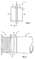
- FIG. 4 Such a separate component is shown in FIG. 4.
- the component can be an injection molded part made of a plastic material or a foamed one Molded part made of a plastic foam material or as a pressed part made of organic Materials as well as synthetic and natural rubbers.
- the connecting element 7 constructed in the manner of a tube has in Roll longitudinal direction 4 three areas arranged side by side.
- the middle area 8 is designed as a support or spacing area. He defines in assembled state the distance between the adjacent rollers 2,3.
- On this central region 8 closes in a roll longitudinal direction 4 a first approach 9 which tapers towards its free end 10.
- the longitudinal direction 4 of the roll adjoins the central region 8 with a second attachment 11.
- this second approach 11 tapers towards its free end 12.
- the two Lugs 9, 11 have different diameters. For example, it tapers the first approach 9 starting from the central region 8 towards its free end 10 from 2 inches to 1.8 inches, while the second approach 11 extends from the central area 8 to Free end 12 tapered from 3 inches to 2.6 inches.
- Inside the adapter 7 is one continuous receiving opening 13 is provided for receiving a roller holder (not shown) serves.
- FIG. 5 shows the adapter component 7 already described in FIG. 4, which is used for the connection between a wrapping paper roll 2 and a ribbon 3 is used.
- the middle part 8 of the connecting element 7 protruding beyond the two lugs 9, 11 serves in the final assembly position as a system for the side wall 14 of the gift ribbon reel to be connected 3.
- the gift ribbon reel 3 is already completely connected to the connecting element 15 here.
- This too Connecting element 15 has a central part 17, of which three Fastening arms 16 in the direction of the wrapping paper roll 2 to be connected extend.
- the fastening arms 16 are at equal distances from one another arranged so that the connecting forces in the final assembly state evenly on the Inside circumference 18 of the wrapping paper roll 2 act.
- the mounting arms 16 point from the roll longitudinal direction 4 to the outside.
- the elastic fastening arms 16 in the direction of Roll axis pressed and into the receiving opening 19 of the wrapping paper roll 2nd introduced. There they are then under prestress on the inner circumference 18.
- To the Free ends 20 of the fastening arms 16 are friction elements 21 in the form of three each transversely to the roll longitudinal direction 4 extending latches attached to the Spread the resilient mounting arms 16 the contact closure with the Reinforce inner circumference 18.
Landscapes
- Engineering & Computer Science (AREA)
- Mechanical Engineering (AREA)
- Replacement Of Web Rolls (AREA)
- Unwinding Webs (AREA)
Abstract
- 1
- Materialspender
- 2
- Geschenkpapierrolle
- 3
- Geschenkbandspule
- 4
- Rollenlängsrichtung
- 5
- Stirnseite
- 6
- Kordelspule
- 7
- Erstes Verbindungselement
- 8
- Mittelbereich
- 9
- Erster Ansatz
- 10
- Freiende
- 11
- Zweiter Ansatz
- 12
- Freiende
- 13
- Aufnahmeöffnung
- 14
- Seitenwand
- 15
- Zweites Verbindungselement
- 16
- Befestigungsarm
- 17
- Mittelteil
- 18
- Innenumfang
- 19
- Aufnahmeöffnung
- 20
- Freiende
- 21
- Reibelement
Description
- Fig. 1
- eine erste Ausführungsform eines Materialspenders
- Fig. 2
- eine zweite Ausführungsform eines Materialspenders
- Fig. 3
- eine dritte Ausführungsform des Materialspenders
- Fig. 4
- ein erstes Verbindungselement
- Fig. 5
- einen Materialspender mit einem ersten Verbindungselement
- Fig. 6
- einen Materialspender mit einem zweiten Verbindungselement.
Claims (10)
- Materialspender (1)dadurch gekennzeichnet, dass jede Rolle (2, 3, 6) wenigstens eine Aufnahmeöffnung (19) zur Aufnahme des Verbindungselements (15) und/oder einer Rollenhalterung aufweist, und dass das Verbindungselement als separates Bauteil ausgeführt ist und eine Anzahl von sich im Wesentlichen in Rollenlängsrichtung (4) erstreckenden, federnden Befestigungsarmen (16) zur Ausbildung einer Verbindung mit dem Innenumfang (18) einer benachbarten Rolle aufweist, wobei die Befestigungsarme (16) in geöffneter Stellung radial nach außen stehen derart, dass deren Freienden (20) auf einem Kreis angeordnet sind, dessen Durchmesser größer ist als der Innendurchmesser der Rolle, die mit den Befestigungsarmen (16) verbunden wird.mit einer ersten Rolle (2) für ein Bahnmaterial, insbesondere für ein bahnförmiges Verpackungsmaterial,mit wenigstens einer zweiten Rolle (3, 6) für ein Bindematerial, insbesondere für ein schnur-, streifen- oder bandförmiges Bindematerial, undmit wenigstens einem Verbindungselement (15) zur Verbindung der Rollen miteinander,
- Materialspender (1) nach Anspruch 1,
gekennzeichnet durch
eine formschlüssige Verbindung zwischen den Rollen (2, 3, 6). - Materialspender (1 ) nach Anspruch 1 oder 2,
gekennzeichnet durch
eine kraftschlüssige Verbindung zwischen den Rollen (2, 3, 6). - Materialspender (1 ) nach einem der Ansprüche 1 bis 3,
dadurch gekennzeichnet, dass die Rollen (2, 3, 6) lösbar miteinander verbunden sind. - Materialspender (1) nach einem der Ansprüche 1 bis 4,
dadurch gekennzeichnet, dass die Rollen (2, 3, 6) in Rollenlängsrichtung (4) miteinander verbunden sind. - Materialspender (1) nach einem der Ansprüche 1 bis 5,
dadurch gekennzeichnet, dass das Verbindungselement (15) eine Keil- bzw. Klemmverbindung zwischen den Rollen (2, 3, 6) ausbildet. - Materialspender (1) nach einem der Ansprüche 1 bis 6,
dadurch gekennzeichnet, dass die Befestigungsarme (16) an ihren Freienden (20) Reibelemente (21) zur Ausbildung eines Reibschlusses mit dem Innenumfang (18) einer benachbarten Rolle aufweisen. - Materialspender (1) nach einem der Ansprüche 1 bis 7,
dadurch gekennzeichnet, dass das Verbindungselement (15) zwei Gruppen von Befestigungsarmen (16) aufweisen, deren Freienden (20) in entgegengesetzte Richtungen weisen. - Materialspender (1) nach einem der Ansprüche 1 bis 7,
dadurch gekennzeichnet, dass das Verbindungselement (15) sowohl eine Anzahl von Befestigungsarmen (16) als auch einen sich in Rollenlängsrichtung (4) erstreckenden Ansatz (9, 11) zur Ausbildung einer Verbindung mit dem Innenumfang (18) einer benachbarten Rolle aufweist, wobei die Freienden (10, 20) von Befestigungsarmen (16) und Ansatz (9, 11 ) in entgegengesetzte Richtungen weisen und wobei der Ansatz (9, 11 ) in Richtung auf sein Freiende (10, 12) konisch zuläuft derart, dass er an zumindest einer Stelle einen Durchmesser aufweist, der dem Innendurchmesser der Rolle entspricht, die mit dem Ansatz (9, 11) verbunden wird. - Materialspender (1) nach einem der Ansprüche 1 bis 9,
gekennzeichnet durch
eine die Rollen (2, 3, 6) haltende Rollenhalterung.
Applications Claiming Priority (2)
| Application Number | Priority Date | Filing Date | Title |
|---|---|---|---|
| DE10240375 | 2002-09-02 | ||
| DE10240375A DE10240375A1 (de) | 2002-09-02 | 2002-09-02 | Materialspender |
Publications (2)
| Publication Number | Publication Date |
|---|---|
| EP1400467A2 true EP1400467A2 (de) | 2004-03-24 |
| EP1400467A3 EP1400467A3 (de) | 2004-06-09 |
Family
ID=31724243
Family Applications (1)
| Application Number | Title | Priority Date | Filing Date |
|---|---|---|---|
| EP03019843A Withdrawn EP1400467A3 (de) | 2002-09-02 | 2003-08-29 | Materialspender |
Country Status (4)
| Country | Link |
|---|---|
| US (1) | US20040116263A1 (de) |
| EP (1) | EP1400467A3 (de) |
| CA (1) | CA2439045A1 (de) |
| DE (1) | DE10240375A1 (de) |
Family Cites Families (13)
| Publication number | Priority date | Publication date | Assignee | Title |
|---|---|---|---|---|
| US1533802A (en) * | 1925-04-14 | Adhesive plaster or tape roller | ||
| US1692503A (en) * | 1928-11-20 | Means pop | ||
| BE498594A (de) * | ||||
| US1051427A (en) * | 1912-01-18 | 1913-01-28 | Frank Mccluskey | Joint for tubular piling. |
| US1944582A (en) * | 1930-08-12 | 1934-01-23 | Gen Cable Corp | Mandrel |
| US2647700A (en) * | 1951-07-12 | 1953-08-04 | Lathrop Harvey | Dispensing spool of adhesive tape and supporting enclosure therefor |
| US3438589A (en) * | 1967-03-08 | 1969-04-15 | Georgia Pacific Corp | Flexible sheet material rolls having internal supporting means adapted to fall out of a dispenser automatically |
| US3371776A (en) * | 1967-04-27 | 1968-03-05 | Badger Plug Comp | Double plug for roll-supporting cores |
| US3441127A (en) * | 1968-01-16 | 1969-04-29 | Hallmark Cards | Gift wrapping ensemble and holder therefor |
| US3690528A (en) * | 1970-11-20 | 1972-09-12 | Pinkerton S Inc | Watchclock tape storage unit |
| US4153157A (en) * | 1978-02-22 | 1979-05-08 | Perkins Papers Ltd. | Packaging of gift wrap sheet material |
| DE9406941U1 (de) * | 1994-04-26 | 1994-06-23 | Monheimer Ketten- und Metallwarenindustrie Pötz & Sand GmbH & Co KG, 40789 Monheim | Vorrichtung zur Lagerung von Ketten, Seile o.dgl. tragenden Spulen |
| US6669818B2 (en) * | 2000-06-28 | 2003-12-30 | Metso Paper Karlstad Ab | Shortened layout from dryer to reel in tissue machine |
-
2002
- 2002-09-02 DE DE10240375A patent/DE10240375A1/de not_active Ceased
-
2003
- 2003-08-28 US US10/650,819 patent/US20040116263A1/en not_active Abandoned
- 2003-08-29 EP EP03019843A patent/EP1400467A3/de not_active Withdrawn
- 2003-09-02 CA CA002439045A patent/CA2439045A1/en not_active Abandoned
Also Published As
| Publication number | Publication date |
|---|---|
| CA2439045A1 (en) | 2004-03-02 |
| DE10240375A1 (de) | 2004-03-18 |
| EP1400467A3 (de) | 2004-06-09 |
| US20040116263A1 (en) | 2004-06-17 |
Similar Documents
| Publication | Publication Date | Title |
|---|---|---|
| DE4434566C2 (de) | Paraffiniereinrichtung | |
| DE69128186T2 (de) | Nachfüllbarer Klebebandspender | |
| DE68915065T2 (de) | Axial verformbare Hülse. | |
| DE60121215T2 (de) | Kabelrolle | |
| DE3816183A1 (de) | Kassette zur aufnahme einer spule | |
| DE2064648A1 (de) | Tragvorrichtung für Draht-, Kabel- und Bandmaterialrollen, insbesondere für Stacheldrahtrollen | |
| DE3134824A1 (de) | Vorrichtung zur achsenlosen lagerung sowie zum auf- und ablaengen und gleichzeitigen messen von spulenkoerpern | |
| EP0101542B1 (de) | Magazinierungsorgan für Ringläufer | |
| DE2931053A1 (de) | Abgabevorrichtung fuer blattfoermiges, insbesondere auf einem halter aufgebrachtes material | |
| DE2527292A1 (de) | Selbstspannende achse fuer wickelhuelsen | |
| DE10240375A1 (de) | Materialspender | |
| DE2362485A1 (de) | Spule fuer eine maschine zur umhuellung von kabeln | |
| DE2107877A1 (de) | Spulen- und Spindelbaugruppe mit magnetischer Spulenhaltevorrichtung | |
| DE19917767C1 (de) | Wickelträger zur Aufnahme von Garn | |
| EP0485886B1 (de) | Verwendung einer Vorrichtung zur Aufnahme von Spulen | |
| DE4103110A1 (de) | Garnspulenhalter | |
| DE4437623A1 (de) | Vorrichtung zur Aufnahme einer Hülse für ein oder mit einem abspulbaren Band | |
| EP0001790A1 (de) | Drahtbremsvorrichtung, insbesondere für Wickelmaschinen | |
| DE202008011252U1 (de) | Wickelspule | |
| DE202025105818U1 (de) | Kernersatzadapter für kernlose Folienrollen | |
| DE3818896C2 (de) | ||
| DE202023106929U1 (de) | Kernersatzadapter für kernlose Folienrollen | |
| DE7531948U (de) | Distanz-vorrichtung fuer spulenhuelsen | |
| EP3000340A1 (de) | Fadenzuführvorrichtung | |
| DE102007000630A1 (de) | Wickelhülsenanordnung für eine Rollenwickeleinrichtung, Wickelhülse und Rollenwickeleinrichtung |
Legal Events
| Date | Code | Title | Description |
|---|---|---|---|
| PUAI | Public reference made under article 153(3) epc to a published international application that has entered the european phase |
Free format text: ORIGINAL CODE: 0009012 |
|
| AK | Designated contracting states |
Kind code of ref document: A2 Designated state(s): AT BE BG CH CY CZ DE DK EE ES FI FR GB GR HU IE IT LI LU MC NL PT RO SE SI SK TR |
|
| AX | Request for extension of the european patent |
Extension state: AL LT LV MK |
|
| PUAL | Search report despatched |
Free format text: ORIGINAL CODE: 0009013 |
|
| AK | Designated contracting states |
Kind code of ref document: A3 Designated state(s): AT BE BG CH CY CZ DE DK EE ES FI FR GB GR HU IE IT LI LU MC NL PT RO SE SI SK TR |
|
| AX | Request for extension of the european patent |
Extension state: AL LT LV MK |
|
| 17P | Request for examination filed |
Effective date: 20040910 |
|
| AKX | Designation fees paid |
Designated state(s): AT BE BG CH CY CZ DE DK EE ES FI FR GB GR HU IE IT LI LU MC NL PT RO SE SI SK TR |
|
| STAA | Information on the status of an ep patent application or granted ep patent |
Free format text: STATUS: THE APPLICATION IS DEEMED TO BE WITHDRAWN |
|
| 18D | Application deemed to be withdrawn |
Effective date: 20060404 |