EP1400721A1 - Befestigungsvorrichtung für Trommelbremskabel - Google Patents
Befestigungsvorrichtung für Trommelbremskabel Download PDFInfo
- Publication number
- EP1400721A1 EP1400721A1 EP03292266A EP03292266A EP1400721A1 EP 1400721 A1 EP1400721 A1 EP 1400721A1 EP 03292266 A EP03292266 A EP 03292266A EP 03292266 A EP03292266 A EP 03292266A EP 1400721 A1 EP1400721 A1 EP 1400721A1
- Authority
- EP
- European Patent Office
- Prior art keywords
- brake
- brake lever
- strut
- cable
- resilient member
- Prior art date
- Legal status (The legal status is an assumption and is not a legal conclusion. Google has not performed a legal analysis and makes no representation as to the accuracy of the status listed.)
- Granted
Links
- 230000007246 mechanism Effects 0.000 claims description 11
- 230000002401 inhibitory effect Effects 0.000 claims description 3
- 230000002265 prevention Effects 0.000 abstract description 2
- 238000000034 method Methods 0.000 description 6
- 230000008569 process Effects 0.000 description 6
- 229910000639 Spring steel Inorganic materials 0.000 description 4
- 238000003780 insertion Methods 0.000 description 3
- 230000037431 insertion Effects 0.000 description 3
- 230000000717 retained effect Effects 0.000 description 3
- 238000004519 manufacturing process Methods 0.000 description 2
- 238000005452 bending Methods 0.000 description 1
- 230000008859 change Effects 0.000 description 1
- 230000002452 interceptive effect Effects 0.000 description 1
- 239000000463 material Substances 0.000 description 1
- 238000012986 modification Methods 0.000 description 1
- 230000004048 modification Effects 0.000 description 1
- 230000000149 penetrating effect Effects 0.000 description 1
- 230000002093 peripheral effect Effects 0.000 description 1
- 238000003466 welding Methods 0.000 description 1
Images






Classifications
-
- F—MECHANICAL ENGINEERING; LIGHTING; HEATING; WEAPONS; BLASTING
- F16—ENGINEERING ELEMENTS AND UNITS; GENERAL MEASURES FOR PRODUCING AND MAINTAINING EFFECTIVE FUNCTIONING OF MACHINES OR INSTALLATIONS; THERMAL INSULATION IN GENERAL
- F16D—COUPLINGS FOR TRANSMITTING ROTATION; CLUTCHES; BRAKES
- F16D65/00—Parts or details
- F16D65/14—Actuating mechanisms for brakes; Means for initiating operation at a predetermined position
- F16D65/16—Actuating mechanisms for brakes; Means for initiating operation at a predetermined position arranged in or on the brake
- F16D65/22—Actuating mechanisms for brakes; Means for initiating operation at a predetermined position arranged in or on the brake adapted for pressing members apart, e.g. for drum brakes
-
- B—PERFORMING OPERATIONS; TRANSPORTING
- B60—VEHICLES IN GENERAL
- B60T—VEHICLE BRAKE CONTROL SYSTEMS OR PARTS THEREOF; BRAKE CONTROL SYSTEMS OR PARTS THEREOF, IN GENERAL; ARRANGEMENT OF BRAKING ELEMENTS ON VEHICLES IN GENERAL; PORTABLE DEVICES FOR PREVENTING UNWANTED MOVEMENT OF VEHICLES; VEHICLE MODIFICATIONS TO FACILITATE COOLING OF BRAKES
- B60T11/00—Transmitting braking action from initiating means to ultimate brake actuator without power assistance or drive or where such assistance or drive is irrelevant
- B60T11/04—Transmitting braking action from initiating means to ultimate brake actuator without power assistance or drive or where such assistance or drive is irrelevant transmitting mechanically
- B60T11/046—Using cables
-
- F—MECHANICAL ENGINEERING; LIGHTING; HEATING; WEAPONS; BLASTING
- F16—ENGINEERING ELEMENTS AND UNITS; GENERAL MEASURES FOR PRODUCING AND MAINTAINING EFFECTIVE FUNCTIONING OF MACHINES OR INSTALLATIONS; THERMAL INSULATION IN GENERAL
- F16D—COUPLINGS FOR TRANSMITTING ROTATION; CLUTCHES; BRAKES
- F16D2121/00—Type of actuator operation force
- F16D2121/14—Mechanical
-
- F—MECHANICAL ENGINEERING; LIGHTING; HEATING; WEAPONS; BLASTING
- F16—ENGINEERING ELEMENTS AND UNITS; GENERAL MEASURES FOR PRODUCING AND MAINTAINING EFFECTIVE FUNCTIONING OF MACHINES OR INSTALLATIONS; THERMAL INSULATION IN GENERAL
- F16D—COUPLINGS FOR TRANSMITTING ROTATION; CLUTCHES; BRAKES
- F16D2125/00—Components of actuators
- F16D2125/18—Mechanical mechanisms
- F16D2125/58—Mechanical mechanisms transmitting linear movement
- F16D2125/60—Cables or chains, e.g. Bowden cables
- F16D2125/62—Fixing arrangements therefor, e.g. cable end attachments
-
- F—MECHANICAL ENGINEERING; LIGHTING; HEATING; WEAPONS; BLASTING
- F16—ENGINEERING ELEMENTS AND UNITS; GENERAL MEASURES FOR PRODUCING AND MAINTAINING EFFECTIVE FUNCTIONING OF MACHINES OR INSTALLATIONS; THERMAL INSULATION IN GENERAL
- F16D—COUPLINGS FOR TRANSMITTING ROTATION; CLUTCHES; BRAKES
- F16D2125/00—Components of actuators
- F16D2125/18—Mechanical mechanisms
- F16D2125/58—Mechanical mechanisms transmitting linear movement
- F16D2125/64—Levers
Definitions
- This invention relates to a mechanical shoe expander and more particularly to a brake cable connecting apparatus for connecting a brake cable with a mechanical operating mechanism mainly comprised of a strut and a brake lever.
- a typical brake cable connecting apparatus comprises a mechanical actuator having a strut, a plate-like brake lever which is retained in the strut and which is pivotally mounted on the strut, and a pivot pin.
- the mechanical actuator is positioned between a pair of brake shoes and then the strut and the brake lever as components of the mechanical actuator engage with the corresponding brake shoes.
- the brake cable connected with the brake lever is operated in a cable operating direction, the brake lever rotates about a pivotally supported point with the strut. Therefore the engaging part of the strut against one brake shoe and the engaging part of the brake lever against the other brake shoe move apart from each other.
- the brake cable is connected with the brake lever; thereafter a holder is clipped on the strut so as to set the brake lever at a certain position in the wider space of the strut.
- the other type of a holder may be rotatably integrated with the strut. (Refer to FIGS. 5, 6, 7, and 8 of the Japanese provisional patent publication number 2001-349360.)
- the engaging parts of the brake lever and the strut against the corresponding brake shoes move to approach each other because of the spring force of the shoe return spring, and the brake lever abuts against the bridge of the strut.
- This clearance becomes wider when the brake cable is connected with the brake lever and becomes widest during the brake cable operation.
- the brake shoes For the purpose of effectuating a braking force, the brake shoes need to rotate so as to fill up the clearance on either side, depending upon the rotational direction of the brake drum. Therefore, a higher impact load is applied to the anchor, thereby giving lower durability and causing an intensive impact noise.
- the holder needs to be designed with sufficient size to be clipped on the outside of the strut, which increases material costs. Furthermore, in order to prevent the holder from detaching from the strut, both the holder and the strut require additional, custom fitting features, which also increases the manufacturing costs thereof.
- the conventional separate holder is inconvenient for handling and has the possibility of getting lost.
- the holder needs to be pushed and clipped on the strut to attach to the strut when the brake cable is connected with the brake lever.
- the holder needs to rotate in order to establish the attachment to the strut after the brake cable is connected with the brake lever. Therefore, the conventional structure requires more work process.
- employing the separate holder creates the possibility that an attaching work of the holder is accidentally omitted.
- Employing the integrated holder creates the possibility of failing to rotate the same and further creates the possibility of being attached in an inappropriate position if misassembled.
- This invention is made to improve the above-points and to provide a brake cable connecting apparatus with a simple structure offering a simple and accurate ability to assemble.
- this invention presents a brake cable connecting apparatus of a brake actuating mechanism for a drum brake
- the brake actuating mechanism comprises: a strut engaging with one brake shoe and a brake lever positioned in a space formed between two facing surface walls of the strut and engaging with the other brake shoe; a proximal end of the brake lever is pivotally supported between the two facing surface walls of the strut while a brake cable is connected to a free end of the brake lever by a connecting pin and the brake actuating mechanism moves the brake shoes away from each other as a result of relative rotation of the strut and brake lever about a pivotally supporting point there between by operation of the brake cable, wherein a resilient member is provided on a rotating trajection of the brake lever relative to the strut; when the brake lever, at an external position out of the space of the strut where the connecting pin can link the brake cable and the brake lever, rotates and moves in a cable operating direction, either the brake lever or the strut deforms
- the brake cable connecting apparatus described above can provide a simple connection between the free end of the brake lever and the brake cable by the connecting pin.
- the resilient member as a result of only operating the brake cable, can prevent disengagement of the brake cable from the brake lever.
- This structure can also eliminate the possibility of omitting a manual attaching work of the holder.
- the brake cable connecting apparatus as described above may have the resilient member installed in the strut.
- the brake cable connecting apparatus as described above may have the resilient member installed in the brake lever.
- the brake cable connecting apparatus as disclosed above may be such that an operating portion that makes the resilient member deform is formed on the resilient member, when the operating portion is operated while rotating the brake lever in the cable releasing direction from the interior position to the exterior position, an abutment of the brake lever or the strut against the resilient member is released, thereby permitting a passage of the free end of the brake lever.
- This disclosure facilitates disengaging the brake cable from the brake lever.
- the resilient member can be deformed as a result of only operating the operating portion. Therefore, the brake cable can be taken away from the brake lever.
- FIG. 1 is a plan view showing an example of the drum brake employing the brake cable connecting apparatus of Example 1;
- FIG. 2 is a cross-section view taken along the line II-II of FIG. 1;
- FIG. 3 is an exploded isometric view of the brake cable connecting apparatus of Example 1;
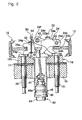
- FIG. 4 is a view explaining operation of the mechanical actuator of Example 1 and explaining a condition where the connecting hole of the free end of the brake lever appears above the opening of the space formed in the strut at the cable releasing side;
- FIG. 5 is a cross-section view taken along the line V-V of FIG. 4;
- FIG. 6 is a view explaining operation of the mechanical actuator of Example 1 and explaining a condition where the inner cable is operated to pass the connecting hole of the free end of the brake lever into the space of the strut;
- FIG. 7 is a view explaining the structure of the brake cable connecting apparatus of Example 2 and explaining a condition where the connecting hole of the free end of the brake lever appears above the opening of the space formed in the strut at the cable releasing side;
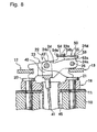
- FIG. 8 is a view explaining the operation of the mechanical actuator of Example 2 and explaining a condition where the inner cable is operated to pass the connecting hole of the free end of the brake lever into the space of the strut, thereby preventing the brake lever from rotating in the cable releasing direction.
- FIG. 9 is an isometric view of the resilient member of Example 2.
- FIG. 10 is a view explaining the structure and operation of the brake cable connecting apparatus of Example 3 and explaining a condition where the connecting hole of the free end of the brake lever appears above the opening of the space formed in the strut at the cable releasing side;
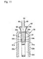
- FIG. 11 is a cross-section view of FIG. 10 taken along the line XI-XI;
- FIG. 12 is a view explaining the operation of the mechanical actuator of Example 3 and explaining a condition where the inner cable is operated to pass the connecting hole of the free end of the brake lever into the space of the strut, thereby preventing the brake lever from rotating in the cable releasing direction.
- a brake cable connecting apparatus of this invention will be explained below.
- Example 1 of this invention will be explained with reference to FIGS. 1-6.
- a pair of brake shoes 12 and 13 is moveably supported on a back plate 11 fixed to a stationary part 10 of a vehicle body by a shoe hold mechanism (not shown in the figures) .
- Lower ends of the brake shoes are supported by a wall portion 16a of an anchor 16 and upper adjacent end thereof (not shown in the figures) are connected by a connecting mechanism (not shown in the figures).
- One shoe return spring (not shown in the figures) is extended between the upper ends of the brake shoes 12 and 13, which maintains an abutment between the connecting mechanism and the upper ends of the brake shoes 12, 13, while lower shoe return spring 19 is extended between the lower ends of the brake shoes 12 and 13, which maintains an abutment between the lower ends of the brake shoes 12, 13 and the anchor 16.
- a mechanical actuator 22, extending between the lower adjacent ends of the brake shoes 12 and 13, comprises a strut 23, a brake lever 24, a pivot pin 25, and a washer 26 and is positioned between both brake shoes 12 and 13 adjacent to the wall portion 16a of the anchor 16.
- the strut 23 has two facing surfaces with a space there between.
- the brake lever 24 is positioned in the space of the strut 23 and a resilient member 30, restricting rotational movement of the brake lever 24 in both rotational directions, is mounted on the left side within the space of the strut 23.
- the anchor 16 comprises the aforesaid wall portion 16a and a base 16b, together making an L shape in cross section.
- the base 16b is fixed to the stationary part 10 of the vehicle with the back plate 11 by insertion bolts 20, 21.
- FIG. 3 is an exploded isometric view showing the mechanical actuator 22, the resilient member 30, a brake cable 40, and a connecting pin 43. Components of them will be explained with reference to FIG. 3.
- the strut 23 as a component of the mechanical actuator 22 is made of a piece of plate, which is folded to make a U-shape thereby forming the two facing surface walls 23b and further, has a bridge 23a at an upper portion thereof in FIG. 3.
- a wider space 23c exists at a central region of the strut 23 in a longitudinal direction between the two facing surface walls 23b and a narrower space 23d exists at a right side of the strut 23 in the longitudinal direction between the two facing surface walls 23b.
- Left end portion of the two facing surface walls 23b have shoe engagement grooves 23e, while right end portion of the two facing surface walls 23b have pivot holes 23f.
- An inner surface walls forming the wider space 23c at a superposed portion side is reserved for the resilient member 30 to be clipped.
- the brake lever 24 as a component of the mechanical actuator 22 is made of a piece of plate and is positioned and retained in the space 23c, 23d of the strut 23.
- a proximal portion 24a at a right side of the brake lever 24 has a shoe engagement groove 24b.
- a protrusion 24c, immediately forming above the shoe engagement groove 24b, has a pivot hole 24d though which the pivot pin 25 penetrates.
- a washer 26 is clipped on the top of the pivot pin 25 penetrating through one of the pivot holes 23f, the pivot hole 24d, and the other of the pivot holes 23f, so that the brake lever 24 is pivotally supported relative to the strut 23.
- a clockwise rotation of the brake lever 24 according to FIG. 2 is restricted because of abutting an upper end surface of the brake lever 24 against the bridge 23a of the strut 23.
- a free end 24e at the left side of the brake lever 24 has a connecting hole 24f to connect the cable end 42, fixed on the tip of an inner cable 41, together making the brake cable 40, by the connecting pin 43.
- a projection 24g is formed on the peripheral surface of the free end 24e interfering with the later described resilient member 30 while rotating the brake lever 24.
- the strut 23 and the brake lever 24, both components of the mechanical actuator 22, have protrusions 23g and 24h at the cable operating side, which abut against heads of the insertion bolts 20 and 21, respectively.
- the resilient member 30 is deformed to allow the free end 24e to move from the exterior position of the strut 23 to an interior position of the strut 23 when the brake lever 24 rotates in the cable operating direction.
- the resilient member 30 interferes the brake lever 24 and prevents the brake lever 24 from rotating back in a cable releasing direction. This example describes a situation when the resilient member 30 is mounted on the strut 23.
- the resilient member 30 of this example is made from a strip of spring steel with a bit narrower width than a width of the wider space 23c of the strut 23 by bent.
- the resilient member 30 has a pair of clipping strips 31 and 32 clipping on top and bottom surfaces of the strut 23 in FIG. 3 after the clipping strip 31 passes through the wider space 23c.
- the resilient member 30 also has a resilient stopper 33 projecting at the side of the bridge 23a within the wider space 23c on a rotating trajection of the projection 24g of the brake lever 24.
- the resilient member 30 is set to bring the resilient stopper 33 on the rotating trajection of the brake lever 24 causing an interference with the projection 24g, so that after the projection 24g passes beyond the resilient stopper 33, the resilient stopper 33 returns to an initial position, and the projection 24g abuts against the resilient stopper 33 when the brake lever rotates back in the cable releasing direction, thereby preventing the free end 24e from passing back beyond the resilient stopper 33 (as shown in FIG. 2).
- the clipping force of the pair of clipping strips 31 and 32 is set to bear vibration while driving the vehicle and also to prevent clip 30 from disengaging from the strut 23 by any external forces when the projection 24g of the brake lever 24 passes beyond the resilient stopper 33.
- the brake cable 40 disclosed in FIGS. 2 and 3 is comprised of the inner cable 41, an outer casing 44 and another parts, and one end at the drum brake side is structured as follows.
- a guide pipe 45 has one and the other ends, the one end is fixed on the base 16b of the anchor 16 and the other end extends through the back plate 11 and the stationary part 10 of the vehicle.
- One end of the brake cable 40 is inserted into the guide pipe 45 and a casing cap 44a of the outer casing 44 fits in the other end of the guide pipe 45 and is clipped by a ring 46.
- the cable end 42 fixed on the tip of the inner cable 41 has two parallel extension surfaces 42b projecting from a proximal portion 42a, which face each other and are spaced for retaining the brake lever 24 there between and have connecting holes 42c to set the connecting pin 43.
- the free end 24e of the brake lever 24 is put between the extension surfaces 42b, the connecting holes 42c and the connecting hole 24f are aligned and connecting pin 43 penetrates there through.
- the position of the brake lever 24 relative to the strut 23 (a position of the projection 24g of the brake lever 24 relative to the resilient stopper 33 of the resilient member 30 mounted on the strut 23) is set at an initial position shown in FIG. 4.
- the rotational range of the brake lever 24 is restricted to a limited range between a point where the projection 24g abuts against the resilient stopper 33 and a point where a central region of the brake lever 24 abuts against the bridge 23a of the strut 23.
- the free end 24e of the brake lever 24 is positioned above the wider space 23c of the strut 23 at the cable releasing side, and the connecting hole 24f appears at the exterior position of the strut.
- the free end 24e of the brake lever 24 is retained between the two extension surfaces 42b formed on the cable end 42, and the connecting holes 42c, 24f, and 42c are aligned so that connecting pin 43 will penetrate there through to link the brake lever 24 and the cable end 42 as shown in FIGS. 4 and 5.
- the casing cap 44a of the outer casing 44 is fixed on the other end of the guide pipe 45 by the ring 46.
- the connecting pin 43 remains in the wider space 23c (the interior position) of the strut 23, and then the free end 24e of the brake lever 24 can not return to its initial position. Accordingly, the cable end 42 fixed on the tip of the inner cable 41 can not inadvertently be disengaged from the brake lever 24 while transporting the drum brake.
- the brake lever 24 is rotated in the cable releasing direction while manually deforming the resilient stopper 33 backward with a tool or the like, the connecting pin 43 can easily be taken away.
- Example 2 is an embodiment where the resilient member 50 is clipped on the bridge 23a of the strut 23 and the projection 24g is formed on an outside surface around the proximal portion 24a of the brake lever 24.
- the resilient member 50 employed in this example is made of a strip of spring steel, and as shown in FIG. 9 a first clipping strip 54a and a second clipping strip 54b are formed by press on a proximate portion 54 at the left side of the resilient member 50.
- the first and second clipping strips 54a and 54b are used to grab the bridge 23a.
- a resilient stopper 53 is extended at a right side of the resilient member 50 and is curved in the opposite direction relative to the first clipping strip 54a to form a rigid end 53a.
- the rigid end 53a sufficiently extends to interfere with the projection 24g at the proximate portion of the brake lever 24.
- an operation strip 55 is formed on the resilient stopper 53 of the resilient member 50 so as to face the second clipping strip 54b.
- FIG. 7 shows a condition where the cable end 42 is connected with the brake lever 24, the first and second clipping strips 54a and 54b of the resilient member 50 are attached to the bridge 23a of the strut 23, and the rigid end 53a of the resilient stopper 53 extends at a side of the proximal portion 24 of the brake lever 24.
- a position of the projection 24g of the brake lever 24 relative to the rigid end 53a of the resilient member 50 is such that the connecting hole 24f entirely appears at the exterior position of the strut 23 until the projection 24g passes beyond the rigid end 53a.
- the outer casing (not shown in the figures) is fixed on the guide pipe 45, and then if the brake lever 24 attempts to rotate in the cable releasing direction, the projection 24g interferes with the rigid end 53a of the resilient stopper 53, now returned from the deformed state, thereby preventing the rotation of the brake lever 24 in the cable releasing direction as shown in FIG. 8.
- Example 1 Compared with Example 1, this example is more economical because it uses less spring steel to form the resilient member 50.
- the connecting hole 24f of the brake lever 24 is positioned at the exterior position of the strut 23 while manually deforming the resilient stopper 53 backward by using the operation strip 55. Also, the connecting pin 43 can easily be taken away.
- the operation strip 55 is not a prerequisite of this example.
- the resilient stopper 53 may be deformed with fingers by pinching both side surfaces of the resilient stopper 53.
- Example 3 is an embodiment where a resilient member 60, made by bending a piece of spring steel, is mounted on the brake lever.
- the resilient member 60 of this example is comprised of a pair of clipping strips 61, capable of being attached on the outside of the brake lever 24 at the central region, a pair of resilient strips 63 projecting from the clipping strips 61 and tapered to gradually be wider toward the free end (upper end in FIG. 11), and a pair of operation ends 65 extending from the resilient strips 63 and parallel to the clipping strips 61.
- a projection 61a is formed on each facing surface of the pair of clipping strips 61 to fit in each concave section 24k, formed at each side of the brake lever 24.
- the resilient member 60 is set in an initial position after fitting the projections 61a in the concave sections 24k.
- the concave sections 24k formed at both sides of the brake lever 24 can be produced at the time the connecting hole 24f or the pivot hole 24d are formed simply with a die change, thereby eliminating an extra process.
- the bridge 23a of the strut 23 has a notch 23h.
- the resilient member 60 is attached to the brake lever 24 at the central region, and the resilient strips 63 are positioned outside of the notch 23h (the cable release side).
- the connecting hole 24f of the brake lever 24 entirely appears at the exterior position of the strut above the opening of the wider space 23c.
- the cable end 42 is connected with the free end 24e of the brake lever 24 by the connecting pin 43, and in the case where the brake lever 24 rotates in the cable operating direction, the tapered resilient strips 63 of the resilient member 60, as shown in FIG. 11, are deformed inward as they slide on the side surface of the notch 23h, formed on the bridge 23a, allowing the brake lever 24 to pass into the wider space 23c (the interior position) in the cable operating direction in order to reach the condition shown in FIG. 12.
- the brake lever 24 is rotated in the cable releasing direction so that the connecting hole 24f entirely appears at the exterior of the strut 23 while manually deforming the resilient strips 63 backward by pinching the pair of operation ends 65 of the resilient member 60 projecting from the strut 23 by fingers, the connecting pin 43 can easily be taken away.
- the resilient strips 63 of the resilient member 60 interfere with the strut 23 at two locations, thereby ensuring a pin disengagement prevention function while the drum brake is being transported and increasing efficiency in disengaging the connection between the free end 24e of the brake lever 24 and the cable end 42.
- This invention is not limited to Examples 1-3.
- the minimum requirement is that when the bake lever, at an external position out of the space formed between the two facing surface falls of the strut where the connecting pin can link the brake cable and the brake lever, rotates andmoves in a cable operating direction, either the brake lever or the strut deforms the resilient member to allow the free end of the brake lever to pass into the internal position in the space formed between two facing plate surfaces of the strut thereby securing the linkage of the connecting pin, the brake lever, and the strut, and thus preventing removal of the connecting pin. Furthermore, when the brake lever at the internal position rotates and moves in a cable releasing direction, either the brake lever or the strut abuts against the resilient member thereby inhibiting the brake lever from rotating in the cable releasing direction.
- This invention provides a simple structure by adding the above-described resilient member so as to allow easy brake cable connecting operation.
- this invention can certainly prevent disengagement of the brake cable from the brake lever and will thereby eliminate the process of manually engaging the holder.
- this invention does not require an extra process to form the brake lever and the strut.
Landscapes
- Engineering & Computer Science (AREA)
- Mechanical Engineering (AREA)
- General Engineering & Computer Science (AREA)
- Transportation (AREA)
- Braking Arrangements (AREA)
Applications Claiming Priority (2)
| Application Number | Priority Date | Filing Date | Title |
|---|---|---|---|
| JP2002270478 | 2002-09-17 | ||
| JP2002270478A JP4096105B2 (ja) | 2002-09-17 | 2002-09-17 | ブレーキケーブルの接続装置 |
Publications (2)
| Publication Number | Publication Date |
|---|---|
| EP1400721A1 true EP1400721A1 (de) | 2004-03-24 |
| EP1400721B1 EP1400721B1 (de) | 2005-06-29 |
Family
ID=31944532
Family Applications (1)
| Application Number | Title | Priority Date | Filing Date |
|---|---|---|---|
| EP03292266A Expired - Lifetime EP1400721B1 (de) | 2002-09-17 | 2003-09-15 | Befestigungsvorrichtung für Trommelbremskabel |
Country Status (4)
| Country | Link |
|---|---|
| US (1) | US6817450B2 (de) |
| EP (1) | EP1400721B1 (de) |
| JP (1) | JP4096105B2 (de) |
| DE (1) | DE60300923D1 (de) |
Cited By (2)
| Publication number | Priority date | Publication date | Assignee | Title |
|---|---|---|---|---|
| EP1808614A1 (de) * | 2006-01-11 | 2007-07-18 | Nisshinbo Industries, Inc. | Mechanischer Bremsaktuator |
| EP2020525A1 (de) * | 2007-07-23 | 2009-02-04 | Nisshinbo Industries, Inc. | Mechanische Bremsbetriebsvorrichtung |
Families Citing this family (14)
| Publication number | Priority date | Publication date | Assignee | Title |
|---|---|---|---|---|
| US7278779B2 (en) * | 2000-11-13 | 2007-10-09 | Back To Basics Products, Llc | Mixer with optional faucet |
| KR100808485B1 (ko) * | 2004-06-01 | 2008-03-03 | 주식회사 만도 | 차량용 주차브레이크장치 |
| JP2006105301A (ja) * | 2004-10-06 | 2006-04-20 | Nisshinbo Ind Inc | ブレーキケーブル接続装置 |
| JP4186012B2 (ja) * | 2005-08-09 | 2008-11-26 | 日清紡績株式会社 | 機械式ブレーキ作動装置 |
| US8875847B2 (en) * | 2005-08-09 | 2014-11-04 | Nisshinbo Holdings, Inc. | Mechanical brake actuator |
| DE112006002895B4 (de) | 2005-10-31 | 2021-12-16 | ZF Active Safety US lnc. | Elektrische Betätigungseinheit für eine Fahrzeugbremsanordnung |
| JP4750006B2 (ja) * | 2006-12-25 | 2011-08-17 | 日清紡ホールディングス株式会社 | ドラムブレーキの作動装置 |
| JP4723542B2 (ja) * | 2007-08-10 | 2011-07-13 | 日清紡ホールディングス株式会社 | ドラムブレーキの作動装置 |
| US8267227B2 (en) * | 2008-07-22 | 2012-09-18 | Akebono Brake Corporation | Lever assembly featuring blind cable assembly |
| US20110100772A1 (en) * | 2009-11-05 | 2011-05-05 | Akebono Corporation (North America) | Cable end retention clip assembly and method |
| JP5844630B2 (ja) * | 2011-12-14 | 2016-01-20 | 曙ブレーキ工業株式会社 | ドラムブレーキ式電動駐車ブレーキ装置 |
| JP5960535B2 (ja) * | 2012-07-27 | 2016-08-02 | 曙ブレーキ工業株式会社 | ドラムブレーキ式電動駐車ブレーキ装置用ケーブル接続装置 |
| JP2016044692A (ja) * | 2014-08-19 | 2016-04-04 | 日清紡ブレーキ株式会社 | ドラムブレーキの機械式ブレーキ作動装置 |
| US11002326B2 (en) * | 2016-08-31 | 2021-05-11 | Mando Corporation | Electronic parking brake |
Citations (4)
| Publication number | Priority date | Publication date | Assignee | Title |
|---|---|---|---|---|
| EP1041301A2 (de) * | 1999-04-01 | 2000-10-04 | Nisshinbo Industries Inc. | Anschlussstück für ein Steuerkabel |
| EP1099874A2 (de) * | 1999-11-11 | 2001-05-16 | Nisshinbo Industries Inc. | Vorrichtung zum Befestigen des Bremskabels einer Feststellbremse |
| EP1174627A1 (de) * | 2000-07-17 | 2002-01-23 | Nisshinbo Industries, Inc. | Bremskabelanschlusselement für Trommelbremsen |
| EP1241370A1 (de) * | 2001-03-13 | 2002-09-18 | SA Thibault Essieux RTN | Spreizhebeleinrichtung für die Bremsbeläge einer Trommelbremse und eine Bremse mit einer solchen Einrichtung |
Family Cites Families (5)
| Publication number | Priority date | Publication date | Assignee | Title |
|---|---|---|---|---|
| US2252860A (en) * | 1939-07-13 | 1941-08-19 | Porsche Kg | Brake mechanism for vehicle road wheels |
| US4822197A (en) * | 1987-02-18 | 1989-04-18 | Demartino John D | Quick connect/disconnect assembly |
| JPH06193659A (ja) * | 1992-12-21 | 1994-07-15 | Nisshinbo Ind Inc | ドラムブレーキの間隙調整停止装置 |
| US5588335A (en) * | 1995-04-28 | 1996-12-31 | Strait; Daniel L. | Torsion lock parking brake actuator with push down release |
| JP4104811B2 (ja) | 2000-06-08 | 2008-06-18 | 曙ブレーキ工業株式会社 | 機械式ドラムブレーキのレバーとケーブルの接続構造 |
-
2002
- 2002-09-17 JP JP2002270478A patent/JP4096105B2/ja not_active Expired - Fee Related
-
2003
- 2003-09-15 DE DE60300923T patent/DE60300923D1/de not_active Expired - Lifetime
- 2003-09-15 EP EP03292266A patent/EP1400721B1/de not_active Expired - Lifetime
- 2003-09-17 US US10/664,831 patent/US6817450B2/en not_active Expired - Lifetime
Patent Citations (4)
| Publication number | Priority date | Publication date | Assignee | Title |
|---|---|---|---|---|
| EP1041301A2 (de) * | 1999-04-01 | 2000-10-04 | Nisshinbo Industries Inc. | Anschlussstück für ein Steuerkabel |
| EP1099874A2 (de) * | 1999-11-11 | 2001-05-16 | Nisshinbo Industries Inc. | Vorrichtung zum Befestigen des Bremskabels einer Feststellbremse |
| EP1174627A1 (de) * | 2000-07-17 | 2002-01-23 | Nisshinbo Industries, Inc. | Bremskabelanschlusselement für Trommelbremsen |
| EP1241370A1 (de) * | 2001-03-13 | 2002-09-18 | SA Thibault Essieux RTN | Spreizhebeleinrichtung für die Bremsbeläge einer Trommelbremse und eine Bremse mit einer solchen Einrichtung |
Cited By (2)
| Publication number | Priority date | Publication date | Assignee | Title |
|---|---|---|---|---|
| EP1808614A1 (de) * | 2006-01-11 | 2007-07-18 | Nisshinbo Industries, Inc. | Mechanischer Bremsaktuator |
| EP2020525A1 (de) * | 2007-07-23 | 2009-02-04 | Nisshinbo Industries, Inc. | Mechanische Bremsbetriebsvorrichtung |
Also Published As
| Publication number | Publication date |
|---|---|
| DE60300923D1 (de) | 2005-08-04 |
| EP1400721B1 (de) | 2005-06-29 |
| US6817450B2 (en) | 2004-11-16 |
| US20040055833A1 (en) | 2004-03-25 |
| JP4096105B2 (ja) | 2008-06-04 |
| JP2004108458A (ja) | 2004-04-08 |
Similar Documents
| Publication | Publication Date | Title |
|---|---|---|
| EP1400721B1 (de) | Befestigungsvorrichtung für Trommelbremskabel | |
| EP1041301B1 (de) | Anordnung zum Verbinden eines Betätigungsseiles | |
| CN112739927A (zh) | 盘式制动器用垫弹簧以及盘式制动器装置 | |
| JP2000104764A (ja) | 車両用ディスクブレーキ | |
| JP4794723B2 (ja) | ブレーキケーブル接続装置 | |
| EP1234995A2 (de) | Befestigung eines Bremsseils am Betätigungshebel einer Trommelbremse | |
| US20220042563A1 (en) | Disc brake device | |
| JP2008281076A (ja) | 軸部材の結合構造 | |
| EP1447586A2 (de) | Kabelverbindungsvorrichtung für eine Trommelbremse | |
| JP7530972B2 (ja) | ボールジョイント | |
| JP4351972B2 (ja) | パンタグラフ型ジャッキ | |
| JP5213818B2 (ja) | 車両用ディスクブレーキ | |
| JP4745803B2 (ja) | ディスクブレーキ | |
| JP4589191B2 (ja) | ディスクブレーキ | |
| JP3387819B2 (ja) | レバー接続部材 | |
| JP2000249175A (ja) | ディスクブレーキ | |
| JP4108889B2 (ja) | ディスクブレーキ | |
| JP7653459B2 (ja) | 抜け止め構造、及び、その抜け止め構造に用いる抜け止め具 | |
| US6360862B1 (en) | Clutch strap | |
| JP2520404Y2 (ja) | パーキングブレーキ機構付きドラムブレーキ | |
| JP2002285740A (ja) | 車両用ドアハンドル装置 | |
| JP4589190B2 (ja) | ディスクブレーキ | |
| JP2000274465A (ja) | 操作ケーブルの接続装置 | |
| EP2020525A1 (de) | Mechanische Bremsbetriebsvorrichtung | |
| JPH08200350A (ja) | リンク連結構造 |
Legal Events
| Date | Code | Title | Description |
|---|---|---|---|
| PUAI | Public reference made under article 153(3) epc to a published international application that has entered the european phase |
Free format text: ORIGINAL CODE: 0009012 |
|
| AK | Designated contracting states |
Kind code of ref document: A1 Designated state(s): AT BE BG CH CY CZ DE DK EE ES FI FR GB GR HU IE IT LI LU MC NL PT RO SE SI SK TR |
|
| AX | Request for extension of the european patent |
Extension state: AL LT LV MK |
|
| 17P | Request for examination filed |
Effective date: 20040921 |
|
| GRAP | Despatch of communication of intention to grant a patent |
Free format text: ORIGINAL CODE: EPIDOSNIGR1 |
|
| AKX | Designation fees paid |
Designated state(s): DE FR |
|
| GRAS | Grant fee paid |
Free format text: ORIGINAL CODE: EPIDOSNIGR3 |
|
| GRAA | (expected) grant |
Free format text: ORIGINAL CODE: 0009210 |
|
| AK | Designated contracting states |
Kind code of ref document: B1 Designated state(s): DE FR |
|
| REF | Corresponds to: |
Ref document number: 60300923 Country of ref document: DE Date of ref document: 20050804 Kind code of ref document: P |
|
| PG25 | Lapsed in a contracting state [announced via postgrant information from national office to epo] |
Ref country code: DE Free format text: LAPSE BECAUSE OF FAILURE TO SUBMIT A TRANSLATION OF THE DESCRIPTION OR TO PAY THE FEE WITHIN THE PRESCRIBED TIME-LIMIT Effective date: 20050930 |
|
| ET | Fr: translation filed | ||
| PLBE | No opposition filed within time limit |
Free format text: ORIGINAL CODE: 0009261 |
|
| STAA | Information on the status of an ep patent application or granted ep patent |
Free format text: STATUS: NO OPPOSITION FILED WITHIN TIME LIMIT |
|
| 26N | No opposition filed |
Effective date: 20060330 |
|
| REG | Reference to a national code |
Ref country code: FR Ref legal event code: PLFP Year of fee payment: 14 |
|
| REG | Reference to a national code |
Ref country code: FR Ref legal event code: PLFP Year of fee payment: 15 |
|
| REG | Reference to a national code |
Ref country code: FR Ref legal event code: CD Owner name: NISSHINBO BRAKE INC., JP Effective date: 20180613 Ref country code: FR Ref legal event code: TP Owner name: NISSHINBO BRAKE INC., JP Effective date: 20180613 |
|
| REG | Reference to a national code |
Ref country code: FR Ref legal event code: PLFP Year of fee payment: 16 |
|
| PGFP | Annual fee paid to national office [announced via postgrant information from national office to epo] |
Ref country code: FR Payment date: 20210812 Year of fee payment: 19 |
|
| PG25 | Lapsed in a contracting state [announced via postgrant information from national office to epo] |
Ref country code: FR Free format text: LAPSE BECAUSE OF NON-PAYMENT OF DUE FEES Effective date: 20220930 |