EP1401357B1 - Implantat mit mitteln zum fixieren an einem körpergefäss - Google Patents
Implantat mit mitteln zum fixieren an einem körpergefäss Download PDFInfo
- Publication number
- EP1401357B1 EP1401357B1 EP02742311A EP02742311A EP1401357B1 EP 1401357 B1 EP1401357 B1 EP 1401357B1 EP 02742311 A EP02742311 A EP 02742311A EP 02742311 A EP02742311 A EP 02742311A EP 1401357 B1 EP1401357 B1 EP 1401357B1
- Authority
- EP
- European Patent Office
- Prior art keywords
- hem
- prosthetic component
- graft
- cord
- body lumen
- Prior art date
- Legal status (The legal status is an assumption and is not a legal conclusion. Google has not performed a legal analysis and makes no representation as to the accuracy of the status listed.)
- Expired - Lifetime
Links
Images




Classifications
-
- A—HUMAN NECESSITIES
- A61—MEDICAL OR VETERINARY SCIENCE; HYGIENE
- A61F—FILTERS IMPLANTABLE INTO BLOOD VESSELS; PROSTHESES; DEVICES PROVIDING PATENCY TO, OR PREVENTING COLLAPSING OF, TUBULAR STRUCTURES OF THE BODY, e.g. STENTS; ORTHOPAEDIC, NURSING OR CONTRACEPTIVE DEVICES; FOMENTATION; TREATMENT OR PROTECTION OF EYES OR EARS; BANDAGES, DRESSINGS OR ABSORBENT PADS; FIRST-AID KITS
- A61F2/00—Filters implantable into blood vessels; Prostheses, i.e. artificial substitutes or replacements for parts of the body; Appliances for connecting them with the body; Devices providing patency to, or preventing collapsing of, tubular structures of the body, e.g. stents
- A61F2/02—Prostheses implantable into the body
- A61F2/04—Hollow or tubular parts of organs, e.g. bladders, tracheae, bronchi or bile ducts
- A61F2/06—Blood vessels
- A61F2/07—Stent-grafts
-
- A—HUMAN NECESSITIES
- A61—MEDICAL OR VETERINARY SCIENCE; HYGIENE
- A61F—FILTERS IMPLANTABLE INTO BLOOD VESSELS; PROSTHESES; DEVICES PROVIDING PATENCY TO, OR PREVENTING COLLAPSING OF, TUBULAR STRUCTURES OF THE BODY, e.g. STENTS; ORTHOPAEDIC, NURSING OR CONTRACEPTIVE DEVICES; FOMENTATION; TREATMENT OR PROTECTION OF EYES OR EARS; BANDAGES, DRESSINGS OR ABSORBENT PADS; FIRST-AID KITS
- A61F2/00—Filters implantable into blood vessels; Prostheses, i.e. artificial substitutes or replacements for parts of the body; Appliances for connecting them with the body; Devices providing patency to, or preventing collapsing of, tubular structures of the body, e.g. stents
- A61F2/82—Devices providing patency to, or preventing collapsing of, tubular structures of the body, e.g. stents
- A61F2/86—Stents in a form characterised by the wire-like elements; Stents in the form characterised by a net-like or mesh-like structure
- A61F2/89—Stents in a form characterised by the wire-like elements; Stents in the form characterised by a net-like or mesh-like structure the wire-like elements comprising two or more adjacent rings flexibly connected by separate members
-
- A—HUMAN NECESSITIES
- A61—MEDICAL OR VETERINARY SCIENCE; HYGIENE
- A61F—FILTERS IMPLANTABLE INTO BLOOD VESSELS; PROSTHESES; DEVICES PROVIDING PATENCY TO, OR PREVENTING COLLAPSING OF, TUBULAR STRUCTURES OF THE BODY, e.g. STENTS; ORTHOPAEDIC, NURSING OR CONTRACEPTIVE DEVICES; FOMENTATION; TREATMENT OR PROTECTION OF EYES OR EARS; BANDAGES, DRESSINGS OR ABSORBENT PADS; FIRST-AID KITS
- A61F2/00—Filters implantable into blood vessels; Prostheses, i.e. artificial substitutes or replacements for parts of the body; Appliances for connecting them with the body; Devices providing patency to, or preventing collapsing of, tubular structures of the body, e.g. stents
- A61F2/82—Devices providing patency to, or preventing collapsing of, tubular structures of the body, e.g. stents
- A61F2/86—Stents in a form characterised by the wire-like elements; Stents in the form characterised by a net-like or mesh-like structure
- A61F2/90—Stents in a form characterised by the wire-like elements; Stents in the form characterised by a net-like or mesh-like structure characterised by a net-like or mesh-like structure
-
- A—HUMAN NECESSITIES
- A61—MEDICAL OR VETERINARY SCIENCE; HYGIENE
- A61F—FILTERS IMPLANTABLE INTO BLOOD VESSELS; PROSTHESES; DEVICES PROVIDING PATENCY TO, OR PREVENTING COLLAPSING OF, TUBULAR STRUCTURES OF THE BODY, e.g. STENTS; ORTHOPAEDIC, NURSING OR CONTRACEPTIVE DEVICES; FOMENTATION; TREATMENT OR PROTECTION OF EYES OR EARS; BANDAGES, DRESSINGS OR ABSORBENT PADS; FIRST-AID KITS
- A61F2/00—Filters implantable into blood vessels; Prostheses, i.e. artificial substitutes or replacements for parts of the body; Appliances for connecting them with the body; Devices providing patency to, or preventing collapsing of, tubular structures of the body, e.g. stents
- A61F2/02—Prostheses implantable into the body
- A61F2/04—Hollow or tubular parts of organs, e.g. bladders, tracheae, bronchi or bile ducts
- A61F2/06—Blood vessels
- A61F2/07—Stent-grafts
- A61F2002/075—Stent-grafts the stent being loosely attached to the graft material, e.g. by stitching
-
- A—HUMAN NECESSITIES
- A61—MEDICAL OR VETERINARY SCIENCE; HYGIENE
- A61F—FILTERS IMPLANTABLE INTO BLOOD VESSELS; PROSTHESES; DEVICES PROVIDING PATENCY TO, OR PREVENTING COLLAPSING OF, TUBULAR STRUCTURES OF THE BODY, e.g. STENTS; ORTHOPAEDIC, NURSING OR CONTRACEPTIVE DEVICES; FOMENTATION; TREATMENT OR PROTECTION OF EYES OR EARS; BANDAGES, DRESSINGS OR ABSORBENT PADS; FIRST-AID KITS
- A61F2230/00—Geometry of prostheses classified in groups A61F2/00 - A61F2/26 or A61F2/82 or A61F9/00 or A61F11/00 or subgroups thereof
- A61F2230/0002—Two-dimensional shapes, e.g. cross-sections
- A61F2230/0028—Shapes in the form of latin or greek characters
- A61F2230/0054—V-shaped
Definitions
- the present invention relates to surgical implants and more particularly to the improvement of fixation and sealing of a prosthetic component to a body lumen.
- EP-A-0 689 806 discloses an implantable tubular prosthesis having cuffs adapted to accommodate stents.
- the prosthesis includes a hollow tubular conduit with cuffs at each end. Each of the cuffs has a closed end and a open end to create a slot for housing the stents.
- the prosthesis may be an implantable tubular intraluminal prosthesis for insertion within a body vessel, where the hollow tubular conduit is radially expandable to buttress the body vessel.
- the prosthesis may be an implantable tubular prosthetic graft for surgical replacement of damaged or diseased existing body vessels.
- the tubular prosthesis and stent combination may be radially expanded so that the stents anchor the prosthesis within the lumen.
- the slots which house the stents, prevent contact between the stents and fluids flowing through the body vessel.
- Standard use of grafts during laparoscopic and open surgical procedures rely on suturing the internal circumference of the artery to the circumference of the graft which results in a stressful and time-consuming operation for a patient and medical professional.
- the present invention provides a device that can be implanted in a body lumen for the purpose of reconstructing or making a repair of the lumen.
- the device includes a prosthetic component having a graft with a hem formed thereon.
- the hem defines an interior space within itself that is used to contain a cord.
- the cord is constructed to contain an absorbent material that expands upon contact with a fluid, such as blood. The expansion of the cord caused by the absorption of the fluid aids in fixating the graft about an irregularly shaped body lumen such as an aorta.
- a method for implanting a device in a body lumen includes introducing the device into the body lumen and contacting the cord with fluid to aid in fixating the prosthetic component against the body lumen.
- one or more attachment tabs are attached to the outer periphery of the prosthetic component.
- Each tab may be configured as a flap unsupported at one end, such as its distal end.
- the tabs are attached at their other end, typically their proximal end, to the outer periphery of the graft and extend radially outward from this attachment point to the graft.
- a part of each tab other than the attached end such as the unattached end, is attached to an adjacent area of the body surrounding the lumen.
- the tabs are provided as fixation devices for the prosthetic component and assist in reducing downward movement by sharing the load of the implant over the length of the prosthetic component.
- a method for implanting a device involves introducing the device in a body lumen and attaching the second part of the attachment tab to an adjacent area of the body surrounding the prosthetic component.
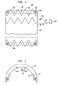
- the device 100 comprises a prosthetic component 115 which includes a graft 130 and may also include a stent 140 positioned within the inside circumference of the graft 130.
- the prosthetic component includes a stent.
- the prosthetic component 115 may consist solely of a graft, which may be desirable when the device is deployed laparoscopically or during open surgical procedures.
- Graft 130 is comprised of a woven fabric such as Dacron, polyester, or polytetrafluoroethylene, to form a cylindrical wall surrounding stent 140.
- Stent 140 is a wire mesh and can be of any suitable type and configuration as are well known in the art.
- stent 140 may be braided, or filamentary, or laser cut, or etched and may be self-expandable or balloon-expandable.
- One exemplary form of a self-expanding stent is made from a shape-memory alloy of nickel and titanium.
- Fig. 1 shows a first hem 110 at a distal end of prosthetic component 115 and also illustrates another embodiment of the invention by the inclusion of a second hem 120 at a proximal end of the prosthetic component 115.
- proximal shall mean a location closer to an access point from outside the body and the term “distal” shall mean a location farther away from the access point, which is typically in the leg of a patient.
- the first hem 110 and the second hem 120 are similarly constructed as described herein below using the first hem 110 as an example.
- the graft 130 has a first hem 110 forming a casing 150 which defines an interior space 152 therein.
- an absorbent cord 160 made of a material such as Merocel ® polymer or a similar absorbent material that can predictably absorb a fluid and controllably expand as a result of this absorption.
- the fluid used to first contact the absorbent cord 160 might initially be a locally administered saline solution for the purpose of establishing fixation while the flow of blood is impeded in the early stages of implant. Initially, or in the absence of pressurized fluid, the cord may only partially absorb the fluid, such as at the areas of the cord exposed to the fluid. When the flow of blood is restored, the blood itself will contact the absorbent cord 160 and will be absorbed to provide continued further fixation.
- the first hem 110 has an appearance of a hem such as may be formed along or around the bottom of a skirt or at the bottom of the legs of trousers. In the case of the first hem 110, it may be constructed by folding a portion of the material of graft 130 over and onto itself and attaching it to itself to form casing 150 defining interior space 152. The hem need not necessarily be at an end of graft 130.
- the absorbent cord 160 is enclosed within the interior space 152 and can have any shape suitable to accommodate the particular application. More specifically, the material of cord 160, when dry, can be compressed into any regular or irregular shape as needed. Such compression might be needed to place the device in a delivery catheter.
- the absorbent cord 160 can have a flat ribbon shape which reduces the profile of the device.
- first hem 110 is preferably sufficiently ductile to form a suitable interior area to contain the cord and to conform to irregular shape of the body lumen.
- first hem 110 is constructed separately without folding over the material of the graft 130.
- Such a separately constructed first hem 110 has a casing 150 made from a separate material other than the graft 130 and uses the separate material to form interior space 152 for containing the absorbent cord 160.
- the first hem 110 constructed in this manner is then attached to the graft 130 at the proper location by sewing, gluing, or weaving to the graft as a separate component.
- first hem 110 enlarged to better illustrate the bio-absorbable coating 170 applied to the absorbent cord 160 by unwrapping the casing 150.
- the absorbent cord 160 has a bio-absorbable coating 170 applied to its outer circumference which controls the rate and amount of fluid that enters into the absorbent material.
- a "bio-absorbable coating” shall mean any material which can be applied as a layer over the cord and which gradually dissolves upon exposure to bodily fluid at a known rate.
- Bio-absorbable coating materials which can be used for the bio-absorbable coating include gelatin; polylactic acid; polyglycolic acid, polysaccharides such as celluloses, starches, dextrans, alginates and derivatives; and chlorhexidine gluconate, among others.
- the bio-absorbable coating thickness may be varied to regulate the amount of absorption and the type of bio-absorbable coating may be selected to absorb certain pre-determined fluids, such as blood.
- a plurality of holes 180 may be pierced in the casing 150 of the first hem 110 for the purpose of increasing the porosity of the first hem 110.
- the number of holes and the size of the holes are determined by the amount of the porosity desired. Referring to Figs. 1 and 2, there are shown holes 180 penetrating the casing 150 from a radially inner border 112 of the casing.
- the material around hem 110 may have a different permeability from the remainder of the graft 130 as desired.
- a graft 130 having a first permeability at areas remote from the hem 110 and a second permeability, greater than the first permeability, at or around the hem 110. More preferably, it may be desirable for radially inner border 112 to have a relatively high permeability while radially outer border 114 has a very low permeability to minimize leakage, such as endoleaks.
- First hem 110 is positioned and attached around the outer circumference at the distal end of prosthetic component 115.
- the first hem 110 is positioned so that the radial outward pressure imparted by stent 140 is equally distributed about prosthetic component 115 notwithstanding any body lumen shape irregularity encountered at the junction of the hem 110 and the inside diameter of the body lumen.
- the stent 140 is disposed radially inside of the graft 130 and contacts inner border 112 of hem 110.
- Figs. 1 and 2 illustrate the position of the first hem 110 at the distal end of prosthetic component 115.
- the first hem 110 is comprised of a material selected to be ductile.
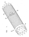
- Fig. 3 is a diagram illustrating the device 100 having its distal end, with the first hem 110, positioned within and attached to the inside circumference of a typical irregularly shaped aorta and the proximal end of device 100, without the use of the second hem 120, within irregularly shaped iliac arteries.
- Fig. 1 shows the first hem 110 positioned at the distal end of the device 100 so that a portion of a the stent 140 extends beyond or distal to the most distal part of the affixed or integrally constructed first hem 110.
- the stent 140 is made up of a series of hoops, with each hoop being one row of the filaments comprising the stent 140. This extension promotes in-growth of tissue with the stent to improve fixation over time after implantation.
- Fig. 1 also shows the second hem 120 similarly positioned however at the proximal end of the device 100 so that a portion of a hoop remains extended beyond or proximal of the most proximal part of the affixed or integrally constructed second hem 120.
- the device 100 having the stent 140 disposed radially inside of the graft 130 with the first hem 110 formed thereon preferably has at least one hoop of the stent 140 distal relative to the first hem 110.
- FIG. 6 is a cross-sectional view of an introducer 700 for an implant of the present invention.
- the prosthetic component 115 with either the first hem 110 or both the first hem 110 and the second hem 120 attached thereto as described above is configured for storage and delivery in a dry and compressed form.
- the first and second hems 110 and 120 in the compressed state each have a thickness of less than 0.85 ⁇ m (30 thousandths of an inch). It is this compressed thinness that permits the use of the prosthetic component 115 with the first and second hems 110 and 120 of the invention to be delivered endovascularly through the femoral or iliac arteries.
- the introducer 700 may be used to deploy a device suitable for treatment of an abdominal aorta aneurysm.
- a device suitable for treatment of an abdominal aorta aneurysm could have two portions - a proximal portion for deployment in an aorta and a distal portion for deployment in an iliac artery, as is well known in the art.
- Introducer 700 includes outer sheath 701, which is a cylindrical tube adapted to be inserted percutaneously or by "cut-down" procedures into the vasculature from an entry point to the location within the body lumen where the prosthetic component 115 is to be implanted.
- Distal portion pusher 702 is a cylindrical tube having an outside diameter smaller than the inside diameter of outer sheath 701. Distal portion pusher 702 is preferably slideable throughout the length of outer sheath 701. Disposed within distal portion pusher 702 is proximal portion pusher 703. Proximal portion pusher 703 is a cylindrical tube slidably contained within distal portion pusher 702. Proximal portion pusher 703 is preferably adapted to slide throughout the entire length of distal portion pusher 702. Disposed within proximal portion 703 is balloon catheter 704. Balloon catheter 704 is adapted to slide within proximal portion pusher 103. At the distal end of balloon catheter 704 is nose cone 706. Balloon 707 is attached to balloon catheter 704 between nose cone 706 and the distal end of distal portion pusher 702.
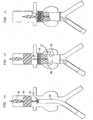
- Figs. 7a, 7b and 7c are sequential cross-sectional views of the bifurcation of the abdominal aortic artery during introduction of an implant according to the present invention.
- the introducer 700 of Fig. 6 may be used to deploy the implant shown in Figs. 7b and 7c, it may be desirable to use an introducer with only one pusher, since the implant shown has only one portion.
- the prosthetic component 115 shown in Figs 7b and 7c are partially cut away to illustrate better the stent 140 within the graft 130 and the location of the hem 110.
- the introducer is passed through an entry point (not shown). This insertion may be accomplished using well known percutaneous or cut-down techniques.
- Introducer 700 is then delivered to the desired delivery location within the body lumen.
- introducer 700 is positioned and balloon 707, if needed, may be inflated above the renal arteries.
- outer sheath 701 is withdrawn until prosthetic component 115 emerges from outer sheath 701 as shown in Figs. 7a and 7b.
- outer sheath 701 is then completely withdrawn until prosthetic component 115 is deployed into the aorta as shown in Fig. 7b.
- Balloon 707 is then deflated and withdrawn inside distal portion of the prosthetic component 115 where balloon 707 is re-inflated to aid in seating the prosthetic component 115, as shown in Fig. 7c.
- Introducing the prosthetic component 115 into the body lumen to effectuate the implantation involves first compressing the device into an introducer 700 in a known manner. The introducer 700 is then inserted into the body lumen and positioned such that the prosthetic component 115 is at a predetermined location. It is probable that during the positioning process and even within the confines of introducer 700, cord 160 will contact body fluid. It is for that reason that an absorption impediment coating is applied to the outer surface of cord 160. Then, part of the introducer is withdrawn to cause expansion of the implant to its decompressed size.
- the cord 160 which is by this time diminished of absorption impeding coating is made fully available by full withdrawal of the introducer to bring about a totally immersed contact with fluid to aid in fixating the prosthetic component 115 against the body lumen.
- This can be achieved by directing a fluid, such as pressurized saline solution, to the cord.
- a fluid such as pressurized saline solution
- this may be done by first aligning the outside circumference of the hem 110 with the inside diameter of the body lumen then removing an impediment to the flow of fluid within the body lumen to the cord 160, such as by deflating balloon 707 and allowing blood to flow and contact the cord 160.
- FIG. 1 there is also shown a second embodiment of the invention having a second hem 120 constructed of the same material and constructed in the same manner as first hem 110. It is noted however that whereas hem 110 is located and attached at the distal end of prosthetic component 115, second hem 120 is positioned and attached around the circumference of the proximal end of prosthetic component 115.
- Figs. 4 illustrates a preferred embodiment of a tab extension spur 230 which is used during a laparoscopic or endovascular procedure.
- At least one tab extension spur 230 is made from the stent material, such as by weaving, and is an integral part of the stent 140. It is made to append along the outer periphery of the graft 130 and for attachment to at least one tab 200 for the purpose of radially extending the tab to contact an adjacent area of the body along the outer periphery of the prosthetic component 115.
- Tab extension spur 230 is pre-inserted into the at least one tab 200 prior to compression for use in the introducer.
- Tab extension spur 230 although part of the stent 140, may be constructed by weaving in the shape of a spur, such that the spur lies adjacent the outer periphery of the prosthetic component during introduction but protrudes radially outward from the circumference of the graft 130 when decompression occurs.
- FIG. 8 illustrates another exemplary embodiment of the invention.
- a bifurcated prosthetic component 930 having a hem 110, containing an absorbing cord 160, is attached at a distal end to an aortic artery 940 with the bifurcated proximal ends extending into the iliac branches 950 and 960 for the common iliac arteries.
- a second prosthetic component 920 is used to attach to the proximal end of the bifurcated prosthetic component 930.
- Second prosthetic component 920 having hem 110 is attached around the outer circumference at the distal end of prosthetic component 920.
- Hem 110 is positioned so that the radial outward pressure imparted by a stent or fixator improves distribution of the radial outward pressure about the periphery of prosthetic component 920 regardless of any prosthetic component 930 shape irregularities encountered at the junction of the hem 110 and the inside diameter of the prosthetic component 930.
- the prosthetic component 920 is disposed radially inside of the iliac artery portion of prosthetic component 930 and with cord 160 expanded, due to absorption of fluid, forms a concentric circle of contact with the interior wall to seal and fixate the two prosthetic components together.
- a straight modular prosthetic component may also be used in connection with this embodiment.
- a hem 110a affixed proximal to the proximal end of iliac branch 950.
- Hem 110a may be provided for the purpose of preventing second prosthetic component 920 from sliding distally into the iliac branch 950. More specifically, if a force is imparted to second prosthetic component 920 to cause movement of second prosthetic component 920 distally, the abutment of hem 110a against the proximal end of iliac branch 950 would stop such movement.
- the device of the present invention may be used in the treatment of abdominal aortic aneurysm, thoracic aortic aneurysm, occlusive disease, or SFA, among others.
- Some of the advantages of the present invention have been disclosed that provide an absorbent cord in a hem that expands on contact with fluid to create an increased surface area for contacting the walls of a body lumen that will reduce the possibility of downward movement of the implant.
- the invention will allow the prosthetic component to conform to any variation in the body lumen shape and will assist in sealing the junction of the prosthetic component and the body lumen at the implant.
Landscapes
- Health & Medical Sciences (AREA)
- Gastroenterology & Hepatology (AREA)
- Pulmonology (AREA)
- Cardiology (AREA)
- Oral & Maxillofacial Surgery (AREA)
- Transplantation (AREA)
- Engineering & Computer Science (AREA)
- Biomedical Technology (AREA)
- Heart & Thoracic Surgery (AREA)
- Vascular Medicine (AREA)
- Life Sciences & Earth Sciences (AREA)
- Animal Behavior & Ethology (AREA)
- General Health & Medical Sciences (AREA)
- Public Health (AREA)
- Veterinary Medicine (AREA)
- Prostheses (AREA)
- Surgical Instruments (AREA)
Claims (18)
- Vorrichtung zur Implantation (100) in ein Körperlumen, umfassend:einen prothetischen Bestandteil (115), der ein Implantat (130) mit einem auf dem Implantat ausgebildeten Saum (110) umfasst, wobei der Saum (110) einen Innenraum (152) definiert; undeinen Faden (160), der im Innenraum (152) angeordnet ist und sich nach Absorption einer Flüssigkeit ausdehnt, um die Befestigung des prothetischen Bestandteils am Körperlumen zu unterstützen.
- Vorrichtung nach Anspruch 1, wobei der prothetische Bestandteil ferner einen Stent (140) umfasst, der radial im Inneren des Implantats (130) angeordnet ist.
- Vorrichtung nach Anspruch 1, wobei der Saum am distalen Ende des prothetischen Bestandteils (115) angeordnet ist.
- Vorrichtung nach Anspruch 3, wobei das Implantat (130) ferner einen zweiten Saum (120) umfasst, der am proximalen Ende des prothetischen Bestandteils angeordnet ist und einen zweiten Innenraum definiert, und wobei die Vorrichtung ferner einen zweiten Faden umfasst, der im zweiten Innenraum angeordnet ist.
- Vorrichtung nach Anspruch 3, wobei sich der Faden (160) in einem zusammengedrückten Zustand befindet, bevor er mit einer Flüssigkeit in Kontakt gebracht wird.
- Vorrichtung nach Anspruch 5, wobei die Stärke des Fadens (160) im komprimierten Zustand weniger als 0,85 µm (dreißig Tausendstel Zoll) beträgt.
- Vorrichtung nach Anspruch 1, wobei der Faden (160) die Form eines flachen Bands aufweist.
- Vorrichtung nach Anspruch 1, wobei der Faden eine Form aufweist, die aus der Gruppe ausgewählt ist, die aus ringförmig, kreisförmig, halbkreisförmig, D-förmig, rechteckig, achteckig, trapezförmig, dreieckig und quadratisch besteht.
- Vorrichtung nach Anspruch 1, die ferner eine Außenbeschichtung (170) auf dem Faden (160) umfasst, wobei sich die Beschichtung unter Einfluss einer Flüssigkeit auflöst, um die Geschwindigkeit zu verändern, mit der sich der Faden (160) nach dem Einsetzen der Vorrichtung (100) ausdehnt.
- Vorrichtung nach Anspruch 1, wobei der Saum (110) Löcher (180) aufweist, um die Porosität des Saums anzupassen, damit eine Flüssigkeit mit dem Faden (160) in Kontakt kommen kann.
- Vorrichtung nach Anspruch 1, wobei der Saum (110) ausreichend duktil ist, um sich unregelmäßigen Formen anzupassen.
- Vorrichtung nach Anspruch 2, wobei der Saum (110) so angeordnet ist, dass der Stent distal relativ zum Saum hervorragen kann.
- Vorrichtung nach Anspruch 12, wobei sich mindestens ein Reif des Stents (140) distal relativ zum Saum befindet.
- Vorrichtung nach Anspruch 1, wobei das Implantat (130) in Bereichen, die vom Saum (110) entfernt sind, eine erste Durchlässigkeit aufweist, und am Saum eine zweite Durchlässigkeit aufweist, die größer ist als die erste Durchlässigkeit.
- Vorrichtung nach Anspruch 1, ferner umfassend einen Befestigungsstreifen (200), der einen ersten Teil aufweist, der an dem Implantat befestigt ist, und einen zweiten Teil (230), der sich vom ersten Teil aus radial nach außen ausdehnt, um an einem angrenzenden Körperbereich, der den prothetischen Bestandteil umgibt, befestigt zu werden.
- Vorrichtung zur Implantation in ein Körperlumen nach Anspruch 1, umfassend:einen prothetischen Bestandteil, der ein Implantat mit einem Saum umfasst, der auf dem Implantat ausgebildet ist, wobei der Saum einen Innenraum definiert;einen Stent, der radial im Inneren des Implantats angeordnet ist;einen Faden, der im Innenraum angeordnet ist und sich nach der Absorption einer Flüssigkeit ausdehnt, um die Befestigung des prothetischen Bestandteils am Körperlumen zu unterstützen;mindestens einen Befestigungsstreifen, der einen ersten Teil aufweist, der am Außenumfang des Implantats befestigt ist, und einen zweiten Teil, der dafür eingerichtet ist, sich vom ersten Teil aus radial nach außen auszudehnen, um an einem angrenzenden Körperbereich, der den prothetischen Bestandteil umgibt, befestigt zu werden; undmindestens einen Streifendehnungsring, der entlang dem Außenumfang des Implantats als Teil des Stents ausgestaltet und an mindestens einem Streifen befestigt ist, um den Streifen radial auszudehnen, um den angrenzenden Körperbereich zu berühren.
- Vorrichtung zur Implantation in ein Körperlumen nach Anspruch 1, umfassend:einen ersten prothetischen Bestandteil, der ein erstes Implantat umfasst;einen zweiten prothetischen Bestandteil, der ein zweites Implantat umfasst, der einen ersten Saum aufweist, wobei der erste Saum einen Innenraum definiert und ein Abschnitt des zweiten prothetischen Bestandteils so angepasst ist, dass er im ersten prothetischen Bestandteil angeordnet werden kann, sodass der erste Saum die Innenwand des ersten prothetischen Bestandteils berührt; undeinen Faden, der im Innenraum angeordnet ist und sich nach der Absorption einer Flüssigkeit ausdehnt, um die Befestigung des zweiten prothetischen Bestandteils am ersten prothetischen Bestandteil zu unterstützen.
- Vorrichtung nach Anspruch 17, wobei der zweite prothetische Bestandteil ferner einen zweiten Saum umfasst, der proximal zum proximalen Ende des ersten prothetischen Bestandteils radial um den zweiten prothetischen Bestandteil herum angeordnet ist, um der Bewegung des zweiten prothetischen Bestandteils in distale Richtung standzuhalten.
Applications Claiming Priority (3)
| Application Number | Priority Date | Filing Date | Title |
|---|---|---|---|
| US898936 | 2001-07-03 | ||
| US09/898,936 US6994722B2 (en) | 2001-07-03 | 2001-07-03 | Implant having improved fixation to a body lumen and method for implanting the same |
| PCT/US2002/020259 WO2003003945A2 (en) | 2001-07-03 | 2002-06-26 | Implant having means for fixation to a body lumen and method for implanting the same |
Publications (2)
| Publication Number | Publication Date |
|---|---|
| EP1401357A2 EP1401357A2 (de) | 2004-03-31 |
| EP1401357B1 true EP1401357B1 (de) | 2007-04-04 |
Family
ID=25410256
Family Applications (1)
| Application Number | Title | Priority Date | Filing Date |
|---|---|---|---|
| EP02742311A Expired - Lifetime EP1401357B1 (de) | 2001-07-03 | 2002-06-26 | Implantat mit mitteln zum fixieren an einem körpergefäss |
Country Status (9)
| Country | Link |
|---|---|
| US (1) | US6994722B2 (de) |
| EP (1) | EP1401357B1 (de) |
| JP (1) | JP4384909B2 (de) |
| AT (1) | ATE358459T1 (de) |
| AU (1) | AU2002315457A1 (de) |
| CA (1) | CA2451665C (de) |
| DE (1) | DE60219313T2 (de) |
| ES (1) | ES2284881T3 (de) |
| WO (1) | WO2003003945A2 (de) |
Families Citing this family (88)
| Publication number | Priority date | Publication date | Assignee | Title |
|---|---|---|---|---|
| US6951572B1 (en) * | 1997-02-20 | 2005-10-04 | Endologix, Inc. | Bifurcated vascular graft and method and apparatus for deploying same |
| US6395019B2 (en) * | 1998-02-09 | 2002-05-28 | Trivascular, Inc. | Endovascular graft |
| US20060122691A1 (en) * | 1998-12-03 | 2006-06-08 | Jacob Richter | Hybrid stent |
| US6261316B1 (en) | 1999-03-11 | 2001-07-17 | Endologix, Inc. | Single puncture bifurcation graft deployment system |
| US8034100B2 (en) * | 1999-03-11 | 2011-10-11 | Endologix, Inc. | Graft deployment system |
| US6602280B2 (en) * | 2000-02-02 | 2003-08-05 | Trivascular, Inc. | Delivery system and method for expandable intracorporeal device |
| US6454799B1 (en) | 2000-04-06 | 2002-09-24 | Edwards Lifesciences Corporation | Minimally-invasive heart valves and methods of use |
| AU2002230661A1 (en) * | 2000-11-15 | 2002-05-27 | Endologix, Inc. | Implantable vascular graft |
| US7267685B2 (en) * | 2000-11-16 | 2007-09-11 | Cordis Corporation | Bilateral extension prosthesis and method of delivery |
| US6761733B2 (en) * | 2001-04-11 | 2004-07-13 | Trivascular, Inc. | Delivery system and method for bifurcated endovascular graft |
| US20040138734A1 (en) * | 2001-04-11 | 2004-07-15 | Trivascular, Inc. | Delivery system and method for bifurcated graft |
| US6733521B2 (en) | 2001-04-11 | 2004-05-11 | Trivascular, Inc. | Delivery system and method for endovascular graft |
| AU2002360765C1 (en) * | 2001-12-20 | 2009-06-11 | Trivascular, Inc. | Advanced endovascular graft |
| US20100016943A1 (en) * | 2001-12-20 | 2010-01-21 | Trivascular2, Inc. | Method of delivering advanced endovascular graft |
| US7125464B2 (en) | 2001-12-20 | 2006-10-24 | Boston Scientific Santa Rosa Corp. | Method for manufacturing an endovascular graft section |
| US7147661B2 (en) * | 2001-12-20 | 2006-12-12 | Boston Scientific Santa Rosa Corp. | Radially expandable stent |
| US6776604B1 (en) | 2001-12-20 | 2004-08-17 | Trivascular, Inc. | Method and apparatus for shape forming endovascular graft material |
| US7090693B1 (en) | 2001-12-20 | 2006-08-15 | Boston Scientific Santa Rosa Corp. | Endovascular graft joint and method for manufacture |
| ITRM20020596A1 (it) * | 2002-11-27 | 2004-05-28 | Mauro Ferrari | Protesi vascolare ad impianto con tecnica combinata, laparoscopica ed endovascolare, per la cura degli aneurismi dell'aorta addominale, e corredo operativo per il rilascio di una protesi munita di stents di ancoraggio. |
| US8292943B2 (en) * | 2003-09-03 | 2012-10-23 | Bolton Medical, Inc. | Stent graft with longitudinal support member |
| US11259945B2 (en) | 2003-09-03 | 2022-03-01 | Bolton Medical, Inc. | Dual capture device for stent graft delivery system and method for capturing a stent graft |
| US20080264102A1 (en) * | 2004-02-23 | 2008-10-30 | Bolton Medical, Inc. | Sheath Capture Device for Stent Graft Delivery System and Method for Operating Same |
| US20070198078A1 (en) | 2003-09-03 | 2007-08-23 | Bolton Medical, Inc. | Delivery system and method for self-centering a Proximal end of a stent graft |
| US7763063B2 (en) | 2003-09-03 | 2010-07-27 | Bolton Medical, Inc. | Self-aligning stent graft delivery system, kit, and method |
| US11596537B2 (en) | 2003-09-03 | 2023-03-07 | Bolton Medical, Inc. | Delivery system and method for self-centering a proximal end of a stent graft |
| US8500792B2 (en) | 2003-09-03 | 2013-08-06 | Bolton Medical, Inc. | Dual capture device for stent graft delivery system and method for capturing a stent graft |
| US9198786B2 (en) | 2003-09-03 | 2015-12-01 | Bolton Medical, Inc. | Lumen repair device with capture structure |
| US7803178B2 (en) * | 2004-01-30 | 2010-09-28 | Trivascular, Inc. | Inflatable porous implants and methods for drug delivery |
| WO2005079339A2 (en) * | 2004-02-12 | 2005-09-01 | The University Of Akron | Improved stent for use in arteries |
| JP4852033B2 (ja) * | 2004-03-11 | 2012-01-11 | トリバスキュラー インコーポレイテッド | モジュール式血管内移植片 |
| US7758626B2 (en) * | 2004-07-20 | 2010-07-20 | Medtronic Vascular, Inc. | Device and method for delivering an endovascular stent-graft having a longitudinally unsupported portion |
| US8048144B2 (en) * | 2004-11-30 | 2011-11-01 | Scimed Life Systems, Inc. | Prosthesis fixation device and method |
| US20060149364A1 (en) * | 2004-12-31 | 2006-07-06 | Steven Walak | Low profile vascular graft |
| US7306623B2 (en) * | 2005-01-13 | 2007-12-11 | Medtronic Vascular, Inc. | Branch vessel graft design and deployment method |
| US7833263B2 (en) * | 2005-04-01 | 2010-11-16 | Boston Scientific Scimed, Inc. | Hybrid vascular graft reinforcement |
| USD549063S1 (en) | 2005-09-09 | 2007-08-21 | Csav, Inc. | Table clamp for electronic display mount |
| US9585743B2 (en) | 2006-07-31 | 2017-03-07 | Edwards Lifesciences Cardiaq Llc | Surgical implant devices and methods for their manufacture and use |
| US9408607B2 (en) * | 2009-07-02 | 2016-08-09 | Edwards Lifesciences Cardiaq Llc | Surgical implant devices and methods for their manufacture and use |
| US8252036B2 (en) * | 2006-07-31 | 2012-08-28 | Syntheon Cardiology, Llc | Sealable endovascular implants and methods for their use |
| USD561569S1 (en) | 2006-08-28 | 2008-02-12 | Csav, Inc. | Support column for mounting device |
| US20080071343A1 (en) * | 2006-09-15 | 2008-03-20 | Kevin John Mayberry | Multi-segmented graft deployment system |
| US8523931B2 (en) * | 2007-01-12 | 2013-09-03 | Endologix, Inc. | Dual concentric guidewire and methods of bifurcated graft deployment |
| ES2551516T3 (es) * | 2007-06-20 | 2015-11-19 | Atex Technologies, Inc. | Tejido comprimible con poder de recuperación, dispositivos, y métodos |
| US9566178B2 (en) | 2010-06-24 | 2017-02-14 | Edwards Lifesciences Cardiaq Llc | Actively controllable stent, stent graft, heart valve and method of controlling same |
| US9814611B2 (en) | 2007-07-31 | 2017-11-14 | Edwards Lifesciences Cardiaq Llc | Actively controllable stent, stent graft, heart valve and method of controlling same |
| US8066755B2 (en) | 2007-09-26 | 2011-11-29 | Trivascular, Inc. | System and method of pivoted stent deployment |
| US8663309B2 (en) | 2007-09-26 | 2014-03-04 | Trivascular, Inc. | Asymmetric stent apparatus and method |
| US8226701B2 (en) | 2007-09-26 | 2012-07-24 | Trivascular, Inc. | Stent and delivery system for deployment thereof |
| US10159557B2 (en) | 2007-10-04 | 2018-12-25 | Trivascular, Inc. | Modular vascular graft for low profile percutaneous delivery |
| US8328861B2 (en) | 2007-11-16 | 2012-12-11 | Trivascular, Inc. | Delivery system and method for bifurcated graft |
| US8083789B2 (en) | 2007-11-16 | 2011-12-27 | Trivascular, Inc. | Securement assembly and method for expandable endovascular device |
| US8221494B2 (en) | 2008-02-22 | 2012-07-17 | Endologix, Inc. | Apparatus and method of placement of a graft or graft system |
| US8236040B2 (en) | 2008-04-11 | 2012-08-07 | Endologix, Inc. | Bifurcated graft deployment systems and methods |
| HUE047762T2 (hu) | 2008-06-06 | 2020-05-28 | Edwards Lifesciences Corp | Kis profilú transzkatéteres szívbillentyû |
| CN102076281B (zh) * | 2008-06-30 | 2014-11-05 | 波顿医疗公司 | 用于腹主动脉瘤的系统和方法 |
| JP5134729B2 (ja) | 2008-07-01 | 2013-01-30 | エンドロジックス、インク | カテーテルシステム |
| CN106551740B (zh) | 2009-03-13 | 2020-03-27 | 波顿医疗公司 | 用于在手术部位部署腔内假体的系统和方法 |
| US8945202B2 (en) | 2009-04-28 | 2015-02-03 | Endologix, Inc. | Fenestrated prosthesis |
| WO2010127305A2 (en) * | 2009-05-01 | 2010-11-04 | Endologix, Inc. | Percutaneous method and device to treat dissections |
| US10772717B2 (en) | 2009-05-01 | 2020-09-15 | Endologix, Inc. | Percutaneous method and device to treat dissections |
| US8491646B2 (en) | 2009-07-15 | 2013-07-23 | Endologix, Inc. | Stent graft |
| JP5588511B2 (ja) | 2009-07-27 | 2014-09-10 | エンドロジックス、インク | ステントグラフト |
| US20110218617A1 (en) * | 2010-03-02 | 2011-09-08 | Endologix, Inc. | Endoluminal vascular prosthesis |
| US20120109279A1 (en) | 2010-11-02 | 2012-05-03 | Endologix, Inc. | Apparatus and method of placement of a graft or graft system |
| WO2012068298A1 (en) | 2010-11-17 | 2012-05-24 | Endologix, Inc. | Devices and methods to treat vascular dissections |
| WO2012118901A1 (en) | 2011-03-01 | 2012-09-07 | Endologix, Inc. | Catheter system and methods of using same |
| US9827093B2 (en) | 2011-10-21 | 2017-11-28 | Edwards Lifesciences Cardiaq Llc | Actively controllable stent, stent graft, heart valve and method of controlling same |
| US8992595B2 (en) | 2012-04-04 | 2015-03-31 | Trivascular, Inc. | Durable stent graft with tapered struts and stable delivery methods and devices |
| US9498363B2 (en) | 2012-04-06 | 2016-11-22 | Trivascular, Inc. | Delivery catheter for endovascular device |
| EP3141223A1 (de) | 2012-04-12 | 2017-03-15 | Bolton Medical, Inc. | Vorrichtung zur abgabe einer gefässprothese |
| US10561509B2 (en) | 2013-03-13 | 2020-02-18 | DePuy Synthes Products, Inc. | Braided stent with expansion ring and method of delivery |
| US9439751B2 (en) | 2013-03-15 | 2016-09-13 | Bolton Medical, Inc. | Hemostasis valve and delivery systems |
| US10206796B2 (en) | 2014-08-27 | 2019-02-19 | DePuy Synthes Products, Inc. | Multi-strand implant with enhanced radiopacity |
| US10449064B2 (en) | 2015-02-12 | 2019-10-22 | Boston Scientific Scimed, Inc. | Stent with anti-migration feature |
| WO2017004265A1 (en) | 2015-06-30 | 2017-01-05 | Endologix, Inc. | Locking assembly for coupling guidewire to delivery system |
| US20170281331A1 (en) * | 2016-03-31 | 2017-10-05 | Medtronic Vascular, Inc. | Endoluminal prosthetic devices having fluid-absorbable compositions for repair of a vascular tissue defect |
| EP3471659B1 (de) | 2016-06-21 | 2024-10-16 | Medtronic Vascular Inc. | Beschichtete endovaskuläre prothesen zur behandlung von aneurysma |
| US10076428B2 (en) * | 2016-08-25 | 2018-09-18 | DePuy Synthes Products, Inc. | Expansion ring for a braided stent |
| US10292851B2 (en) | 2016-09-30 | 2019-05-21 | DePuy Synthes Products, Inc. | Self-expanding device delivery apparatus with dual function bump |
| JP7430061B2 (ja) * | 2017-02-21 | 2024-02-09 | シルク・ロード・メディカル・インコーポレイテッド | 血管インプラント |
| WO2019017975A1 (en) * | 2017-07-21 | 2019-01-24 | Xinova, LLC | SYSTEMS AND METHODS FOR RADIATION DOSIMETRY |
| AU2019204522A1 (en) | 2018-07-30 | 2020-02-13 | DePuy Synthes Products, Inc. | Systems and methods of manufacturing and using an expansion ring |
| US10456280B1 (en) | 2018-08-06 | 2019-10-29 | DePuy Synthes Products, Inc. | Systems and methods of using a braided implant |
| US10278848B1 (en) | 2018-08-06 | 2019-05-07 | DePuy Synthes Products, Inc. | Stent delivery with expansion assisting delivery wire |
| JP7494444B2 (ja) * | 2018-12-14 | 2024-06-04 | 住友ベークライト株式会社 | アンカーステント |
| US11039944B2 (en) | 2018-12-27 | 2021-06-22 | DePuy Synthes Products, Inc. | Braided stent system with one or more expansion rings |
| WO2021262264A1 (en) | 2020-06-24 | 2021-12-30 | Bolton Medical, Inc. | Anti-backspin component for vascular prosthesis delivery device |
| US12502178B2 (en) | 2022-08-16 | 2025-12-23 | Boston Scientific Scimed, Inc. | Medical device for occluding a left atrial appendage |
Family Cites Families (29)
| Publication number | Priority date | Publication date | Assignee | Title |
|---|---|---|---|---|
| US3726279A (en) * | 1970-10-08 | 1973-04-10 | Carolina Medical Electronics I | Hemostatic vascular cuff |
| US4728328A (en) * | 1984-10-19 | 1988-03-01 | Research Corporation | Cuffed tubular organic prostheses |
| US4652264A (en) | 1985-04-25 | 1987-03-24 | American Cyanamid Company | Prosthetic tubular article |
| US4740207A (en) | 1986-09-10 | 1988-04-26 | Kreamer Jeffry W | Intralumenal graft |
| US5162430A (en) | 1988-11-21 | 1992-11-10 | Collagen Corporation | Collagen-polymer conjugates |
| US5061274A (en) | 1989-12-04 | 1991-10-29 | Kensey Nash Corporation | Plug device for sealing openings and method of use |
| KR920000459B1 (ko) | 1989-12-13 | 1992-01-14 | 재단법인 한국화학연구소 | 다당류 유도체가 도포된 인공혈관과 그 제조방법 |
| NL9101159A (nl) | 1991-07-03 | 1993-02-01 | Industrial Res Bv | Vormvast te maken uitzetbare ring, cylinder of huls. |
| IT1264322B (it) | 1992-07-30 | 1996-09-23 | Lanfranco Callegaro | Esteri di gellano autoreticolato, procedimento di preparazione e loro applicazioni farmaceutiche e biomedico-sanitarie |
| CN1091315A (zh) | 1992-10-08 | 1994-08-31 | E·R·斯奎布父子公司 | 血纤维蛋白封闭剂组合物及其使用方法 |
| US5964744A (en) * | 1993-01-04 | 1999-10-12 | Menlo Care, Inc. | Polymeric medical device systems having shape memory |
| US5855598A (en) | 1993-10-21 | 1999-01-05 | Corvita Corporation | Expandable supportive branched endoluminal grafts |
| US5609627A (en) | 1994-02-09 | 1997-03-11 | Boston Scientific Technology, Inc. | Method for delivering a bifurcated endoluminal prosthesis |
| US5522881A (en) * | 1994-06-28 | 1996-06-04 | Meadox Medicals, Inc. | Implantable tubular prosthesis having integral cuffs |
| NL9500147A (nl) | 1995-01-26 | 1996-09-02 | Industrial Res Bv | Werkwijze voor het uit foliemateriaal vervaardigen van een hulsvormige stent, en stent verkregen onder toepassing van deze werkwijze. |
| US6147168A (en) | 1995-03-06 | 2000-11-14 | Ethicon, Inc. | Copolymers of absorbable polyoxaesters |
| WO1996036297A1 (en) * | 1995-05-19 | 1996-11-21 | Kanji Inoue | Transplantation instrument, method of bending same and method of transplanting same |
| US5820917A (en) | 1995-06-07 | 1998-10-13 | Medtronic, Inc. | Blood-contacting medical device and method |
| US5769882A (en) | 1995-09-08 | 1998-06-23 | Medtronic, Inc. | Methods and apparatus for conformably sealing prostheses within body lumens |
| US5824036A (en) * | 1995-09-29 | 1998-10-20 | Datascope Corp | Stent for intraluminal grafts and device and methods for delivering and assembling same |
| US5871537A (en) * | 1996-02-13 | 1999-02-16 | Scimed Life Systems, Inc. | Endovascular apparatus |
| US5617878A (en) | 1996-05-31 | 1997-04-08 | Taheri; Syde A. | Stent and method for treatment of aortic occlusive disease |
| US5769884A (en) * | 1996-06-27 | 1998-06-23 | Cordis Corporation | Controlled porosity endovascular implant |
| US5718717A (en) | 1996-08-19 | 1998-02-17 | Bonutti; Peter M. | Suture anchor |
| ZA978537B (en) | 1996-09-23 | 1998-05-12 | Focal Inc | Polymerizable biodegradable polymers including carbonate or dioxanone linkages. |
| WO1998030252A1 (en) | 1997-01-09 | 1998-07-16 | Cohesion Technologies, Inc. | Methods and apparatuses for making swellable uniformly shaped devices from polymeric materials |
| US6371982B2 (en) * | 1997-10-09 | 2002-04-16 | St. Jude Medical Cardiovascular Group, Inc. | Graft structures with compliance gradients |
| US6395019B2 (en) * | 1998-02-09 | 2002-05-28 | Trivascular, Inc. | Endovascular graft |
| US6159240A (en) * | 1998-08-31 | 2000-12-12 | Medtronic, Inc. | Rigid annuloplasty device that becomes compliant after implantation |
-
2001
- 2001-07-03 US US09/898,936 patent/US6994722B2/en not_active Expired - Fee Related
-
2002
- 2002-06-26 WO PCT/US2002/020259 patent/WO2003003945A2/en not_active Ceased
- 2002-06-26 ES ES02742311T patent/ES2284881T3/es not_active Expired - Lifetime
- 2002-06-26 AT AT02742311T patent/ATE358459T1/de not_active IP Right Cessation
- 2002-06-26 AU AU2002315457A patent/AU2002315457A1/en not_active Abandoned
- 2002-06-26 EP EP02742311A patent/EP1401357B1/de not_active Expired - Lifetime
- 2002-06-26 CA CA2451665A patent/CA2451665C/en not_active Expired - Fee Related
- 2002-06-26 DE DE60219313T patent/DE60219313T2/de not_active Expired - Lifetime
- 2002-06-26 JP JP2003509961A patent/JP4384909B2/ja not_active Expired - Fee Related
Also Published As
| Publication number | Publication date |
|---|---|
| CA2451665C (en) | 2010-02-23 |
| ES2284881T3 (es) | 2007-11-16 |
| JP4384909B2 (ja) | 2009-12-16 |
| EP1401357A2 (de) | 2004-03-31 |
| WO2003003945A3 (en) | 2003-06-19 |
| ATE358459T1 (de) | 2007-04-15 |
| US6994722B2 (en) | 2006-02-07 |
| JP2004531356A (ja) | 2004-10-14 |
| CA2451665A1 (en) | 2003-01-16 |
| DE60219313D1 (de) | 2007-05-16 |
| DE60219313T2 (de) | 2008-01-03 |
| AU2002315457A1 (en) | 2003-01-21 |
| US20030009211A1 (en) | 2003-01-09 |
| WO2003003945A2 (en) | 2003-01-16 |
Similar Documents
| Publication | Publication Date | Title |
|---|---|---|
| US6994722B2 (en) | Implant having improved fixation to a body lumen and method for implanting the same | |
| AU2002353807B2 (en) | Endovascular aneurysm repair system | |
| EP1513471B1 (de) | Endoluminale vorrichtung mit einer verankerungseinheit | |
| AU725117B2 (en) | Bifurcated vascular graft deployment device | |
| US7029496B2 (en) | Interlocking endoluminal device | |
| US5676697A (en) | Two-piece, bifurcated intraluminal graft for repair of aneurysm | |
| US6918926B2 (en) | System for transrenal/intraostial fixation of endovascular prosthesis | |
| JP4052397B2 (ja) | 腹部大動脈瘤の治療のための内管グラフト | |
| US9427339B2 (en) | Triple-collar stent-graft | |
| US20030204249A1 (en) | Endovascular stent graft and fixation cuff | |
| JPH09117511A (ja) | ステントと血管移植片の結合アセンブリ | |
| CN107072777A (zh) | 用于治疗动脉瘤和其它血管病的装置和方法 | |
| CA2263694A1 (en) | Endovascular prosthetic device, and method of use | |
| MXPA03000268A (es) | Sistema modular para correcion de aneurisma. | |
| EP1795152B1 (de) | Systeme und Vorrichtungen zur Befestigung von Graftsmaterial an intraluminaren Vorrichtungen | |
| JP2011183218A (ja) | 血管内動脈瘤修復システム | |
| MXPA99007689A (en) | Bifurcated vascular graft and method and apparatus for deploying same |
Legal Events
| Date | Code | Title | Description |
|---|---|---|---|
| PUAI | Public reference made under article 153(3) epc to a published international application that has entered the european phase |
Free format text: ORIGINAL CODE: 0009012 |
|
| 17P | Request for examination filed |
Effective date: 20040113 |
|
| AK | Designated contracting states |
Kind code of ref document: A2 Designated state(s): AT BE CH CY DE DK ES FI FR GB GR IE IT LI LU MC NL PT SE TR |
|
| AX | Request for extension of the european patent |
Extension state: AL LT LV MK RO SI |
|
| GRAP | Despatch of communication of intention to grant a patent |
Free format text: ORIGINAL CODE: EPIDOSNIGR1 |
|
| RTI1 | Title (correction) |
Free format text: IMPLANT HAVING MEANS FOR FIXATION TO A BODY LUMEN |
|
| GRAS | Grant fee paid |
Free format text: ORIGINAL CODE: EPIDOSNIGR3 |
|
| GRAA | (expected) grant |
Free format text: ORIGINAL CODE: 0009210 |
|
| AK | Designated contracting states |
Kind code of ref document: B1 Designated state(s): AT BE CH CY DE DK ES FI FR GB GR IE IT LI LU MC NL PT SE TR |
|
| PG25 | Lapsed in a contracting state [announced via postgrant information from national office to epo] |
Ref country code: FI Free format text: LAPSE BECAUSE OF FAILURE TO SUBMIT A TRANSLATION OF THE DESCRIPTION OR TO PAY THE FEE WITHIN THE PRESCRIBED TIME-LIMIT Effective date: 20070404 Ref country code: CH Free format text: LAPSE BECAUSE OF FAILURE TO SUBMIT A TRANSLATION OF THE DESCRIPTION OR TO PAY THE FEE WITHIN THE PRESCRIBED TIME-LIMIT Effective date: 20070404 Ref country code: LI Free format text: LAPSE BECAUSE OF FAILURE TO SUBMIT A TRANSLATION OF THE DESCRIPTION OR TO PAY THE FEE WITHIN THE PRESCRIBED TIME-LIMIT Effective date: 20070404 |
|
| REG | Reference to a national code |
Ref country code: GB Ref legal event code: FG4D |
|
| REG | Reference to a national code |
Ref country code: CH Ref legal event code: EP |
|
| REF | Corresponds to: |
Ref document number: 60219313 Country of ref document: DE Date of ref document: 20070516 Kind code of ref document: P |
|
| REG | Reference to a national code |
Ref country code: IE Ref legal event code: FG4D |
|
| PGFP | Annual fee paid to national office [announced via postgrant information from national office to epo] |
Ref country code: ES Payment date: 20070528 Year of fee payment: 6 |
|
| PG25 | Lapsed in a contracting state [announced via postgrant information from national office to epo] |
Ref country code: SE Free format text: LAPSE BECAUSE OF FAILURE TO SUBMIT A TRANSLATION OF THE DESCRIPTION OR TO PAY THE FEE WITHIN THE PRESCRIBED TIME-LIMIT Effective date: 20070704 |
|
| ET | Fr: translation filed | ||
| PG25 | Lapsed in a contracting state [announced via postgrant information from national office to epo] |
Ref country code: PT Free format text: LAPSE BECAUSE OF FAILURE TO SUBMIT A TRANSLATION OF THE DESCRIPTION OR TO PAY THE FEE WITHIN THE PRESCRIBED TIME-LIMIT Effective date: 20070904 |
|
| REG | Reference to a national code |
Ref country code: CH Ref legal event code: PL |
|
| REG | Reference to a national code |
Ref country code: ES Ref legal event code: FG2A Ref document number: 2284881 Country of ref document: ES Kind code of ref document: T3 |
|
| PG25 | Lapsed in a contracting state [announced via postgrant information from national office to epo] |
Ref country code: AT Free format text: LAPSE BECAUSE OF FAILURE TO SUBMIT A TRANSLATION OF THE DESCRIPTION OR TO PAY THE FEE WITHIN THE PRESCRIBED TIME-LIMIT Effective date: 20070404 |
|
| PGFP | Annual fee paid to national office [announced via postgrant information from national office to epo] |
Ref country code: BE Payment date: 20070411 Year of fee payment: 6 Ref country code: IT Payment date: 20070528 Year of fee payment: 6 |
|
| PG25 | Lapsed in a contracting state [announced via postgrant information from national office to epo] |
Ref country code: DK Free format text: LAPSE BECAUSE OF FAILURE TO SUBMIT A TRANSLATION OF THE DESCRIPTION OR TO PAY THE FEE WITHIN THE PRESCRIBED TIME-LIMIT Effective date: 20070404 Ref country code: MC Free format text: LAPSE BECAUSE OF NON-PAYMENT OF DUE FEES Effective date: 20070630 |
|
| PLBE | No opposition filed within time limit |
Free format text: ORIGINAL CODE: 0009261 |
|
| STAA | Information on the status of an ep patent application or granted ep patent |
Free format text: STATUS: NO OPPOSITION FILED WITHIN TIME LIMIT |
|
| 26N | No opposition filed |
Effective date: 20080107 |
|
| PG25 | Lapsed in a contracting state [announced via postgrant information from national office to epo] |
Ref country code: GR Free format text: LAPSE BECAUSE OF FAILURE TO SUBMIT A TRANSLATION OF THE DESCRIPTION OR TO PAY THE FEE WITHIN THE PRESCRIBED TIME-LIMIT Effective date: 20070705 |
|
| BERE | Be: lapsed |
Owner name: BOSTON SCIENTIFIC LIMITED Effective date: 20080630 |
|
| PG25 | Lapsed in a contracting state [announced via postgrant information from national office to epo] |
Ref country code: BE Free format text: LAPSE BECAUSE OF NON-PAYMENT OF DUE FEES Effective date: 20080630 |
|
| PG25 | Lapsed in a contracting state [announced via postgrant information from national office to epo] |
Ref country code: CY Free format text: LAPSE BECAUSE OF FAILURE TO SUBMIT A TRANSLATION OF THE DESCRIPTION OR TO PAY THE FEE WITHIN THE PRESCRIBED TIME-LIMIT Effective date: 20070404 |
|
| REG | Reference to a national code |
Ref country code: ES Ref legal event code: FD2A Effective date: 20080627 |
|
| PG25 | Lapsed in a contracting state [announced via postgrant information from national office to epo] |
Ref country code: IT Free format text: LAPSE BECAUSE OF NON-PAYMENT OF DUE FEES Effective date: 20080626 Ref country code: LU Free format text: LAPSE BECAUSE OF NON-PAYMENT OF DUE FEES Effective date: 20070626 |
|
| PG25 | Lapsed in a contracting state [announced via postgrant information from national office to epo] |
Ref country code: TR Free format text: LAPSE BECAUSE OF FAILURE TO SUBMIT A TRANSLATION OF THE DESCRIPTION OR TO PAY THE FEE WITHIN THE PRESCRIBED TIME-LIMIT Effective date: 20070404 |
|
| PG25 | Lapsed in a contracting state [announced via postgrant information from national office to epo] |
Ref country code: ES Free format text: LAPSE BECAUSE OF NON-PAYMENT OF DUE FEES Effective date: 20080627 |
|
| PGFP | Annual fee paid to national office [announced via postgrant information from national office to epo] |
Ref country code: DE Payment date: 20130619 Year of fee payment: 12 Ref country code: IE Payment date: 20130611 Year of fee payment: 12 Ref country code: GB Payment date: 20130626 Year of fee payment: 12 |
|
| PGFP | Annual fee paid to national office [announced via postgrant information from national office to epo] |
Ref country code: NL Payment date: 20130608 Year of fee payment: 12 Ref country code: FR Payment date: 20130624 Year of fee payment: 12 |
|
| REG | Reference to a national code |
Ref country code: DE Ref legal event code: R119 Ref document number: 60219313 Country of ref document: DE |
|
| REG | Reference to a national code |
Ref country code: NL Ref legal event code: V1 Effective date: 20150101 |
|
| GBPC | Gb: european patent ceased through non-payment of renewal fee |
Effective date: 20140626 |
|
| REG | Reference to a national code |
Ref country code: IE Ref legal event code: MM4A |
|
| REG | Reference to a national code |
Ref country code: DE Ref legal event code: R119 Ref document number: 60219313 Country of ref document: DE Effective date: 20150101 |
|
| REG | Reference to a national code |
Ref country code: FR Ref legal event code: ST Effective date: 20150227 |
|
| PG25 | Lapsed in a contracting state [announced via postgrant information from national office to epo] |
Ref country code: NL Free format text: LAPSE BECAUSE OF NON-PAYMENT OF DUE FEES Effective date: 20150101 |
|
| PG25 | Lapsed in a contracting state [announced via postgrant information from national office to epo] |
Ref country code: DE Free format text: LAPSE BECAUSE OF NON-PAYMENT OF DUE FEES Effective date: 20150101 Ref country code: IE Free format text: LAPSE BECAUSE OF NON-PAYMENT OF DUE FEES Effective date: 20140626 |
|
| PG25 | Lapsed in a contracting state [announced via postgrant information from national office to epo] |
Ref country code: GB Free format text: LAPSE BECAUSE OF NON-PAYMENT OF DUE FEES Effective date: 20140626 Ref country code: FR Free format text: LAPSE BECAUSE OF NON-PAYMENT OF DUE FEES Effective date: 20140630 |