EP1402971B1 - Dispositif d' alimentation de pièces pour une presse - Google Patents
Dispositif d' alimentation de pièces pour une presse Download PDFInfo
- Publication number
- EP1402971B1 EP1402971B1 EP03255758A EP03255758A EP1402971B1 EP 1402971 B1 EP1402971 B1 EP 1402971B1 EP 03255758 A EP03255758 A EP 03255758A EP 03255758 A EP03255758 A EP 03255758A EP 1402971 B1 EP1402971 B1 EP 1402971B1
- Authority
- EP
- European Patent Office
- Prior art keywords
- carriers
- carrier
- press
- workpiece
- vertically moving
- Prior art date
- Legal status (The legal status is an assumption and is not a legal conclusion. Google has not performed a legal analysis and makes no representation as to the accuracy of the status listed.)
- Expired - Lifetime
Links
- 239000000969 carrier Substances 0.000 claims description 52
- 230000007246 mechanism Effects 0.000 claims description 28
- 230000033001 locomotion Effects 0.000 claims description 24
- 238000011144 upstream manufacturing Methods 0.000 claims description 15
- 230000005540 biological transmission Effects 0.000 claims description 3
- 230000009467 reduction Effects 0.000 description 3
- 238000005096 rolling process Methods 0.000 description 3
- 238000010586 diagram Methods 0.000 description 2
- 239000000463 material Substances 0.000 description 2
- 230000009471 action Effects 0.000 description 1
- 230000008859 change Effects 0.000 description 1
- 238000004519 manufacturing process Methods 0.000 description 1
- 238000012986 modification Methods 0.000 description 1
- 230000004048 modification Effects 0.000 description 1
- 230000001360 synchronised effect Effects 0.000 description 1
Images


Classifications
-
- B—PERFORMING OPERATIONS; TRANSPORTING
- B21—MECHANICAL METAL-WORKING WITHOUT ESSENTIALLY REMOVING MATERIAL; PUNCHING METAL
- B21D—WORKING OR PROCESSING OF SHEET METAL OR METAL TUBES, RODS OR PROFILES WITHOUT ESSENTIALLY REMOVING MATERIAL; PUNCHING METAL
- B21D43/00—Feeding, positioning or storing devices combined with, or arranged in, or specially adapted for use in connection with, apparatus for working or processing sheet metal, metal tubes or metal profiles; Associations therewith of cutting devices
- B21D43/02—Advancing work in relation to the stroke of the die or tool
- B21D43/04—Advancing work in relation to the stroke of the die or tool by means in mechanical engagement with the work
- B21D43/05—Advancing work in relation to the stroke of the die or tool by means in mechanical engagement with the work specially adapted for multi-stage presses
- B21D43/055—Devices comprising a pair of longitudinally and laterally movable parallel transfer bars
Definitions
- the present invention relates to a workpiece carrier apparatus for transfer press machine according to the preamble of claim 1, to carry workpiece to a press station, and to hold workpiece pressed and processed at one press station, and carry it to the next press station for sequential press forming.
- a transfer press machine conducts press operations while carrying workpiece press formed at various press stations to the next press station in sequence, and synchronized with the raising and lowering operation of an upper die.
- the transfer press machine incorporates a workpiece carrier apparatus.
- the workpiece carrier apparatus incorporates a cross bar fitted with a workpiece holder which operates between adjacent press stations in an approximately rectangular movement to constitute a carrier motion.
- Workpiece press formed at an upstream press station is gripped in the workpiece holder and lifted, carried to the next downstream press station, and then lowered and moved onto the lower die of the press station.
- a variety of mechanisms are used for the workpiece carrier apparatus for transfer press machine.
- carriers incorporating a cross bar and are installed at each press station perform feed operation and raising and lowering operation.
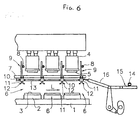
- FIG. 6 shows one example in outline.
- Press stations 6 for forming the workpiece with a press die comprising a lower die 3 installed via a bolster 2, and an upper die 5 placed such as to be capable of being raised and lowered by a slide 4 above the lower die 3, are arranged apart at required spacing at multiple locations along a press line L on a bed 1 installed along the press line L.
- multiple carriers 10 arranged to match the spacing of the press stations 6 are installed on each of the left and right lifting beams 7 such as to be able to run along the press line L, and cross bars 1 extending at right angles to the direction of the press line L and fitted with workpiece holders 12 are arranged between the carriers 10 opposed in the left-right direction, and both ends of the cross bars 11 are supported by the left and right carriers 10.
- adjacent carriers 10 in the direction of the press line L are connected via connecting rods 13, and a rack and pinion mechanism 15 fitted with an AC servo motor 14 is connected to the carrier 10 on one end in the direction of the press line L via a connecting rod 16.
- the carriers 10 and cross bars 11 fitted with the workpiece holders 12 are capable of being moved vertically by the raising and lowering of the lifting beam 7 driven by the AC servo motor 8. Moreover, movement of all carriers 10 in synchronization in the direction of the press line L via the rack and pinion mechanism 15 driven by the AC servo motor 14 and the connecting rods 16 and 13, allows movement of the cross bars 11 fitted with the workpiece holders 12, in the direction of the press line L (see for example, Japanese Unexamined Patent Application, First Publication No. Hei 10-328766).
- Transfer devices for transfer presses of the known type are describe for example in US 4981031, on which the preamble of claim 1 is based, and EP-A-0315381.
- the present invention is a further advance on the aforementioned conventional apparatus, and provides a workpiece carrier apparatus for a transfer press machine in which a different workpeice carrying motion may be set individually for each press station to carry workpiece, as well as allowing the same operation of cross bars fitted with workpiece holders attached to any carrier.
- the workpiece carrier apparatus for a transfer press machine comprises: guide beams which are supported by the guide beams such as to allow movement in a direction of the press line; a plurality of carriers which are supported by the guide beams and as to allow movement in a direction of the press line; cross bars which are provided with workpiece holders and are attached to the carriers; a first carrier mechanism for feeding a carrier located on a most upstream side in the direction of the press line, in the press line direction; and a second carrier mechanism for feeding a plurality of carrier located downstream in the press line direction, in the press line direction, characterised in that the first carrier mechanism is operable independently of the second carrier mechanism and in that the cross bars are attached to the carriers so that they are capable of being raised and lowered with respect to the carriers.
- each of the carriers in this configuration may comprise vertically moving bodies capable of being raised and lowered independently, and a drive device which drives the vertically moving body, and the cross bars may be fitted between vertically moving bodies of mutually opposed carriers on the left and right guide beams.
- the carrier at the most upstream position in the direction of the press line and the other downstream side carries are able to move and carry workpiece independently.
- Sheet material supplied to the press line as workpiece is therefore able to be carried to the first press station by independent movement of the most upstream side carrier.
- independent shift operation is possible with the drive devices provided in each carrier, it is possible to establish individual carrying motions, and to design and manufacture dies in accordance only with essential die functions, and without restrictions on the amount of carrying or raising and lowering.
- the ability to establish optimum individual motions without restriction on the dies of each press station allows a reduction in carrying time, and increases the number of press cycles per unit time, thus raising productivity.
- each of the carriers may comprise a vertically moving body capable of being raised and lowered
- the workpiece carrier apparatus may further comprise drive devices to raise and lower vertically moving bodies of a plurality of groups of adjacent carriers, and a power transmission mechanism connecting the drive devices, and the vertically moving bodies may be raised or lowered simultaneously by any of the drive devices corresponding to the respective groups, and the cross bars may be fitted between the vertically moving bodies of mutually opposed carriers on the left and right guide beams.
- FIG. 1 through FIG. 4 show the outline of an embodiment of a workpiece carrier apparatus for transfer press machine according to the present invention.
- a first press station S1, a second press station S2, a third press station S3, a fourth press station S4, and a fifth press station S5 are established in sequence at required spacing between the upstream side and the downstream side of a press line L at a lower portion of a press frame 17.
- lower dies 20 are respectively installed on bolsters 19 on bases 18 at the press stations S 1, S2, S3, S4, and S5, and slides 21 are installed on the press frame 17 such as to be capable of being moved vertically by a slide drive device 22.
- the upper dies (not shown in drawings) corresponding to the lower dies 20 of each of the press station S1, S2, S3, S4, and S5 are fitted to the bottom faces of the slides 21, and workpiece is press formed and processed at each press station S1, S2, S3, S4, and S5 by the press dies comprised of the upper die and lower die 20.
- This press machine incorporates the following configuration.
- Guide beams 23 on the left and right sides of the press line L are located parallel to the direction of the press line L, and the left and right guide beams 23 are capable of being raised and lowered by a lifting device 24 along the press frame 17. Moreover, a plurality of (seven in the direction of the press line L in the figure) carriers 25a, 25b, 25c, 25d, 25e, 25f, and 25g are each arranged symmetrically left and right, and supported on the left and right guide beams 23 to permit movement in the direction of the press line L. Except for carrier 25a at the most upstream position on the press line L, all adjacent carriers 25b, 25c, 25d, 25e, 25f, and 25g are connected by a connecting rod 26 so that the carriers 25b.
- a first carrier mechanism 28 is provided at the upstream side of the press line L, and it is connected to the aforementioned carrier 25a via a connecting rod 27 so as to move the carrier 25a in the direction of the press line L.
- a second carrier mechanism 30 is provided at the downstream side of the press line L, and it is connected via a connecting rod 29 to the carrier 25g at the last downstream position so as to impart a feed operation to the connecting rod 29 in the direction of the press line L.
- the left and right guide beams 23 have beams 32 of rectangular hollow section, with guide rails 33 of rectangular section projecting both above and below, extending over the full length, and integrally fitted to the top and bottom edges of the outer face of the beams 32.
- Each guide rail 33 projecting above and below has rail faces 33a, 33b, and 33c.
- the bottom end of a rack rod 24a of the lifting device 24 is fitted at the required location on the top edge of the beam 32, and a pinion which is meshed with the rack of the rack rod 24a is connected to a servo motor 24b serving as a drive deice, installed at the top position.
- the pinion is rotated by the servo motor 24b, enabling raising and lowering of the rack rod 24a together with the guide beams 23.
- a guide mechanism 36 comprised of a horizontal guide roller 34 rolling on the rail faces 33b and 33c, and a vertical guide roller 35 rolling on the rail face 33a, is fitted at four locations front and rear and top and bottom on the inside face of a casing 37 open at the bottom, so that the carriers 25a, 25b, 25c, 25d, 25e, 25f, and 25g engage with the upper and lower guide rails 33 on the guide beams 23.
- a servo motor 38 serving as a drive device, is installed on the nape of the casing 37, and a vertically moving body 39 fitted with the cross bar head 31 at the bottom end is inserted inside the casing 37 from the bottom to allow unrestrained movement only in the vertical direction (in the axial direction) along the guide members inside the casing 37.
- the vertically moving body 39 is fitted with a nut member 40.
- a screw member 42 connected to the output shaft 41 of the servo motor 38 and which engages with the nut member 40 passing through in the vertical direction, and the vertically moving body 39 is raised and lowered via the screw member 42 driven by the servo motor 38, thus allowing the cross bar head 31 to move vertically.
- the carriers 25a, 25b, 25c, 25d, 25e, 25f. and 25g of the above configuration are assembled on the guide beams 23, such that the horizontal guide rollers 34 of each guide mechanism 36 fitted at the top and bottom engage with the rail faces 33b and 33c formed on both sides of the vertically projecting portions of the guide rail 33 so as to sandwich these from both sides of the guide rail 33, and the vertical guide rollers 35 engage such as to allow them to roll along the rail faces 33a formed on the top and bottom faces of the guide rail 33.
- Both ends of the cross bars 1 extended horizontally at right angles to the press line L are connected and supported to allow rotation on the cross bar heads 31 supported to allow raising and lowering on the mutually opposed left and right carriers 25a, 25b, 25c, 25d, 25e, 25f, and 25g on either side of the press line L, and each carrier 25a, 25b, 25c, 25d, 25e, 25f, and 25g is driven independently by the servo motor 38 to allow the amount of raising and lowering of the cross bars 11 to be set individually.
- a connecting rod attaching portion 44 with a flange 43 on the tip protrudes at both front and rear ends in the direction of the adjacent carriers 25a, 25b, 25c, 25d, 25e, 25f, and 25g, and the flange 43 of the connecting rod attaching portion 44 is abutted with the flange 45 fitted to the tips of the connecting rods 26, 27, and 29.
- This allows the connecting rod 27 to be connected to the most upstream side carrier 25a, and the connecting rods 26 and 29 to be connected to each of the other carriers 25b, 25c, 25d, 25e. 25f, and 25g respectively.
- the first carrier mechanism 28 for moving the most upstream side carrier 25a in the direction of the press line L has the following configuration as shown in FIG. 1.
- the upper and lower guide rails 33 on the guide beams 23 are assembled via rollers, and a servo motor 47 and a pinion 48 driven by the servo motor 47 are fitted to a upper moving body 46 such that it is able to move along the guide rails 33.
- racks 49 are fixed parallel to the guide beams 23, and pinions 48 are meshed with the racks 49.
- the upper moving body 46 and the carrier 25a are connected via the connecting rod 27, and the pinion 48 is rotated by driving the servo motor 47.
- the configuration of the second carrier mechanism 30 for moving the carriers 25b, 25c, 25d, 25e, 25f, and 25g other than the carrier 25a, in the direction of the press line L is as follows.
- a frame 51 is installed on a base 50 at each of left and right sides of the press line L at approximately the same height as the guide beams 23, a rack 53 is supported on an upper frame 52 on the frame 51 such that it is able to move in the direction of the press line L, an end of the rack 53 on the upstream side in the press line L direction and the last carrier 25g at the downstream side are connected by the connecting rod 29, and the carriers 25b, 25c, 25d, 25e, 25f, and 25g are able to move together with the rack 53.
- a drive device which moves the rack 53 is comprised of pinions 55 rotated by a servo motor 54, installed on an anchor block 56.
- the pinion 55 being meshed with the rack 53, and by rotation of the pinion 55, the rack 53 is moved along the upper frame 52 on the frame 51, thus providing feed for the carriers 25b, 25c, 25d, 25e, 25f, and 25g to carry the workpiece.
- the connecting portion of the connecting rod 29 connecting the rack 53 and the carrier 25g is able to rotate in the vertical direction, and the set position of the guide beams 23 is displaced in the vertical direction so that the feed movement accompanying movement of the rack 53 is transmitted to the carrier 25g smoothly, irrespective of any change in the height of the rack 53 and the carrier 25g.
- the product formed at the last press station S5 at the downstream side in the press line L direction is carried from the press station S5 by the carrier motion of the cross bar 11, and a conveyor 57 to receive and transfer the product to the downstream side is installed such that its height is adjustable.
- the height of the left and right guide beams 23 arranged parallel to the press line L is pre-adjusted to the height of the die for when press forming the workpiece.
- the lifting device 24 is operated to move the guide beams 23 vertically via the rack rod 24a.
- the guide beams 23 When the guide beams 23 are set to the predetermined height, the guide beams 23 remain fixed until the sequence of press operations is complete.
- the most upstream side carrier 25a in the press line L direction is connected to the upper moving body 46 of the first carrier mechanism 28 via the connecting rod 27 to provide independent feed operation by the first carrier mechanism 28.
- the other carriers 25b, 25c, 25d, 25e, 25f, and 25g are interconnected by the connecting rod 26, and the most downstream side carrier 25g is connected to the rack 53 in the second carrier mechanism 30 via the connecting rod 29 to provide feed operation by the second carrier mechanism 30. Press operation is conducted with the mechanism described above.
- Press operation involves carrying the workpiece in sequence between the first press station S 1 and the fifth press station S5 while providing the predetermined press forming.
- Carriers 25b, 25c, 25d, 25e, 25f, and 25g other than the carrier 25a, carrying the workpiece to the first press station S1 are fed simultaneously by driving the servo motor 54 of the second carrier mechanism 30 by remote control, and driven independently by the servo motors 38 on the carriers 25b, 25c, 25d, 25e, 25f, and 25g for raising and lowering of each cross bar 11.
- the predetermined press forming and processing are conducted for each press station S1, S2, S3, S4, and S5, and the workpiece is moved sequentially to the downstream side conveyor 57 from the first press station S1 via the second press station S2.
- This invention allows the most upstream side carrier 25a in the direction of the press line L to be disconnected from the other carriers 25b, 25c, 25d, 25e, 25f, and 25g for separate feed, and each carrier 25a, 25b, 25c, 25d, 25e, 25f, and 25g to be raised and lowered independently. Therefore optimum carrying motion can be set without restriction by the dies at each press station S1, S2, S3, S4, and S5, thus allowing a variety of shapes of sheet, and a reduction in carrying time, and increasing the number of press cycles per unit time, thus enabling productivity to be raised.
- FIG. 5 shows another aspect of the embodiment according to the present invention.
- the servo motors 38 for each carrier 25a, 25b, 25c, 25d, 25e, 25f, and 25g performs lift operation independently by remote operation.
- the carriers 25b, 25c, 25d, 25e, 25f, and 25g other than the most upstream side carrier 25a, two or three adjacent carriers, for example 25b, 25c, and 25d, or 25e, 25f, and 25g, work together to perform lift operation so that the cross bars 11 are raised and lowered in synchronization with each other.
- a single stage or two stage (two stage provided for intermediate position) pulley or chain wheel (chain wheel shown in drawing) 58 is fitted to the screw member 42 connected to the output shaft 41 of the servo motor 38 installed on each carrier 25b. 25c, 25d, 25e, 25f, and 25g, with an endless belt or chain 59 spanning the screw members 42 of the carriers 25b and 25c, and 25c and 25d, or between the screw members 42 of the carriers 25e and 25f, and 25f and 25g.
- This arrangement ensures simultaneous transmission of power by the belt or chain 59 without needing drive from one of the servo motors 38, for either of the two groups of three carriers 25b, 25c, and 25d or 25e, 25f, and 25g, so that the multiple carriers 25b, 25c, and 25d, or 25e, 25f, and 25g are lifted simultaneously and in synchronization, and each cross bar 11 is raised and lowered simultaneously by the same amount, thus lifting the workpiece.
- the present invention is not limited to the various embodiments described above in which carrying and lifting operation of each carrier 25a, 25b, 25c, 25d, 25e, 25f, and 25g is performed by servo control mechanisms employing servo motors 47, 54, and 38 as actuators. Therefore, the servo control may optionally include variable speed control, and it will be understood that other various modifications within the scope of the appended claims are also possible.
Landscapes
- Engineering & Computer Science (AREA)
- Mechanical Engineering (AREA)
- Press Drives And Press Lines (AREA)
Claims (4)
- Dispositif de transport d'une pièce d'oeuvre pour une machine à presse de transfert, comprenant :des poutres de guidage (23) agencées sur le côté de gauche et de droite d'une ligne de presse (L), plusieurs transporteurs (25a, 25b, 25c, 25e, 25f, 25g) supportés par les poutres de guidage (23), de sorte à permettre un déplacement dans une direction de la ligne de presse (L) ;des barres transversales (11) comportant des éléments de retenue de la pièce d'oeuvre (12) et fixées sur les transporteurs (25a, 25b, 25c, 25e, 25f, 25g) ;un premier mécanisme de transport (28) pour amener un premier transporteur (25a) agencé sur un côté amont extrême dans la direction de la ligne de presse (L) dans la direction de la ligne de presse ; etun deuxième mécanisme de transport (30) pour amener plusieurs transporteurs (25b, 25c, 25e, 25f, 25g) agencés en aval du premier transporteur (25a) dans la direction de la ligne de presse ;caractérisé en ce que le premier mécanisme de transport (28) peut être actionné indépendamment du deuxième mécanisme de transport (30) et en ce que les barres transversales (11) sont fixées sur les transporteurs (25a, 25b, 25c, 25e, 25f, 25g), de sorte à pouvoir être soulevées et abaissées par rapport aux transporteurs.
- Dispositif de transport d'une pièce d'oeuvre pour une machine à presse de transfert selon la revendication 1, dans lequel chacun des transporteurs (25a, 25b, 25c, 25e, 25f, 25g) comprend un corps à déplacement vertical (39) pouvant être soulevé et abaissé indépendamment, et un dispositif d'entraînement (38) pour entraîner le corps à déplacement vertical (39) ; et
les barres transversales (11) étant ajustées entre les corps à déplacement vertical (39) des transporteurs mutuellement opposés sur les poutres de guidage de gauche et de droite (23). - Dispositif de transport d'une pièce d'oeuvre pour une machine à presse de transfert selon la revendication 1, dans lequel chacun des transporteurs (25a, 25b, 25c, 25e, 25f, 25g) comprend un corps à déplacement vertical (39) pouvant être soulevé et abaissé ; et
le dispositif de transport de la pièce d'oeuvre comprenant en outre des dispositifs d'entraînement (38) pour soulever et abaisser les corps à déplacement vertical (39) de plusieurs groupes de transporteurs adjacents, et un mécanisme de transmission de l'énergie (59) raccordant les dispositifs d'entraînement (38), les corps à déplacement vertical (39) étant soulevés et abaissés de manière simultanée par un quelconque des dispositifs d'entraînement (38) correspondant aux groupes respectifs ; et
les barres transversales (11) étant ajustées entre les corps à déplacement vertical (39) des transporteurs mutuellement opposés sur les poutres de guidage de gauche et de droite (23). - Dispositif de transport d'une pièce d'oeuvre pour une machine à presse de transfert selon l'une quelconque des revendications 1 à 3, comportant en outre un dispositif de levage (24) soulevant et abaissant les poutres de guidage (23).
Applications Claiming Priority (2)
| Application Number | Priority Date | Filing Date | Title |
|---|---|---|---|
| JP2002271494A JP4269612B2 (ja) | 2002-09-18 | 2002-09-18 | トランスファープレスのワーク搬送装置 |
| JP2002271494 | 2002-09-18 |
Publications (2)
| Publication Number | Publication Date |
|---|---|
| EP1402971A1 EP1402971A1 (fr) | 2004-03-31 |
| EP1402971B1 true EP1402971B1 (fr) | 2006-07-05 |
Family
ID=31973205
Family Applications (1)
| Application Number | Title | Priority Date | Filing Date |
|---|---|---|---|
| EP03255758A Expired - Lifetime EP1402971B1 (fr) | 2002-09-18 | 2003-09-15 | Dispositif d' alimentation de pièces pour une presse |
Country Status (7)
| Country | Link |
|---|---|
| US (1) | US7047790B2 (fr) |
| EP (1) | EP1402971B1 (fr) |
| JP (1) | JP4269612B2 (fr) |
| CA (1) | CA2440962C (fr) |
| DE (1) | DE60306598T2 (fr) |
| ES (1) | ES2268288T3 (fr) |
| MX (1) | MXPA03008257A (fr) |
Families Citing this family (15)
| Publication number | Priority date | Publication date | Assignee | Title |
|---|---|---|---|---|
| TW200616874A (en) * | 2004-09-22 | 2006-06-01 | Hallys Corp | Conveyance device |
| WO2006033370A1 (fr) * | 2004-09-22 | 2006-03-30 | Hallys Corporation | Appareil de transfert |
| JP4796782B2 (ja) * | 2005-04-14 | 2011-10-19 | コマツ産機株式会社 | ワーク搬送装置、プレス機械、およびバー取外方法 |
| US7793819B2 (en) * | 2007-03-19 | 2010-09-14 | Infineon Technologies Ag | Apparatus and method for connecting a component with a substrate |
| DE102007019899B4 (de) | 2007-04-27 | 2009-04-02 | Schuler Pressen Gmbh & Co. Kg | Transferpresse mit uneinheitlichem Stationenabstand |
| US7938249B2 (en) * | 2007-05-31 | 2011-05-10 | Winterborne, Inc. | Shuttle machine for machine tool |
| CN101585245A (zh) * | 2008-05-23 | 2009-11-25 | 北京航天长峰股份有限公司 | 提门滚动装置 |
| JP5389587B2 (ja) * | 2009-09-24 | 2014-01-15 | 株式会社 クニテック | 薄肉曲がり管部材の成形方法及び薄肉曲がり管部材の製造装置 |
| JP2011194428A (ja) * | 2010-03-18 | 2011-10-06 | Aida Engineering Ltd | 搬送装置の破損防止機構およびそれを用いた搬送装置 |
| CN104826955B (zh) * | 2015-04-02 | 2016-08-24 | 创美工艺(常熟)有限公司 | 冲床内置式多工位移模机械手 |
| MX386668B (es) * | 2015-06-17 | 2025-03-19 | Jinan Doublewin Automobile Equipment Eng Co Ltd | Sistema y método de embalaje automático de todas las partes en el final de la línea de estampado. |
| CN105235266A (zh) * | 2015-11-10 | 2016-01-13 | 唐山中材重型机械有限公司 | 建材压机轨道升降装置 |
| CN108856549B (zh) * | 2018-07-26 | 2024-03-26 | 济南二机床集团有限公司 | 一种用于冲压线压机间或多工位压机的搬运装置、系统和方法 |
| CN110666495A (zh) * | 2019-09-30 | 2020-01-10 | 苏州竹日精密机械有限公司 | 一种用于二次压紧绝缘帽和螺丝的机构 |
| CN112722849A (zh) * | 2021-02-03 | 2021-04-30 | 杭州正驰达精密机械有限公司 | 割草机刀片输送装置 |
Family Cites Families (7)
| Publication number | Priority date | Publication date | Assignee | Title |
|---|---|---|---|---|
| US4995505A (en) * | 1987-10-31 | 1991-02-26 | Ishikawajima-Harima Jukogyo Kabushiki Kaisha | Transfer method and device and driving system therefor for transfer presses |
| DE3905073A1 (de) * | 1989-02-18 | 1990-08-23 | Schuler Gmbh L | Umsetzeinrichtung in einer transferpresse o. dgl. umformmaschine |
| JPH05177277A (ja) * | 1991-12-26 | 1993-07-20 | Ishikawajima Harima Heavy Ind Co Ltd | トランスファープレスのワーク搬送装置 |
| DE4418417A1 (de) * | 1994-05-26 | 1995-11-30 | Schuler Pressen Gmbh & Co | Umsetzvorrichtung in einer Umformmaschine, insbesondere einer Transferpresse |
| US5632181A (en) * | 1995-02-23 | 1997-05-27 | Verson, A Division Of Allied Products Corporation | System and method for transferring a work piece in a multi-station press |
| DE19542205A1 (de) * | 1995-11-13 | 1997-05-15 | Schuler Pressen Gmbh & Co | Presse mit kombinierter Transfereinrichtung |
| JPH10328766A (ja) * | 1997-05-29 | 1998-12-15 | Ishikawajima Harima Heavy Ind Co Ltd | トランスファプレス搬送装置 |
-
2002
- 2002-09-18 JP JP2002271494A patent/JP4269612B2/ja not_active Expired - Fee Related
-
2003
- 2003-09-12 MX MXPA03008257A patent/MXPA03008257A/es active IP Right Grant
- 2003-09-15 CA CA002440962A patent/CA2440962C/fr not_active Expired - Fee Related
- 2003-09-15 DE DE60306598T patent/DE60306598T2/de not_active Expired - Lifetime
- 2003-09-15 ES ES03255758T patent/ES2268288T3/es not_active Expired - Lifetime
- 2003-09-15 EP EP03255758A patent/EP1402971B1/fr not_active Expired - Lifetime
- 2003-09-16 US US10/663,224 patent/US7047790B2/en not_active Expired - Fee Related
Also Published As
| Publication number | Publication date |
|---|---|
| US20040177669A1 (en) | 2004-09-16 |
| DE60306598T2 (de) | 2007-06-21 |
| JP2004106012A (ja) | 2004-04-08 |
| ES2268288T3 (es) | 2007-03-16 |
| EP1402971A1 (fr) | 2004-03-31 |
| CA2440962C (fr) | 2007-10-23 |
| JP4269612B2 (ja) | 2009-05-27 |
| DE60306598D1 (de) | 2006-08-17 |
| US7047790B2 (en) | 2006-05-23 |
| MXPA03008257A (es) | 2004-09-03 |
| CA2440962A1 (fr) | 2004-03-18 |
Similar Documents
| Publication | Publication Date | Title |
|---|---|---|
| US7047790B2 (en) | Workpiece carrier apparatus for transfer press machine | |
| US5159827A (en) | Transferring apparatus for transfer press | |
| US7210326B2 (en) | Work transfer apparatus for transfer press | |
| JP4603981B2 (ja) | プレス機械のワーク搬送装置 | |
| EP0315381B1 (fr) | Dispositif de transfert pour presses transferts | |
| KR100878652B1 (ko) | 탠덤 프레스라인의 공작물반송방법 및 공작물반송장치 | |
| JPH02247031A (ja) | 薄板部品の機械加工のためのいくつかのプレスを有するプレス設備 | |
| CN100506421C (zh) | 输送装置 | |
| US6314786B1 (en) | Transfer system | |
| CN109205256B (zh) | 一种围帮暂存排序装置 | |
| US5332079A (en) | Apparatus for conveying plate-form articles | |
| JP4951445B2 (ja) | プレス設備のワーク自動搬送装置 | |
| JP3937520B2 (ja) | トランスファプレスのワーク搬送装置 | |
| WO1994021404A1 (fr) | Dispositif d'alimentation de transfert | |
| JP4224810B2 (ja) | トランスファプレスのワーク搬送装置 | |
| JP4604013B2 (ja) | プレス機械のワーク搬送装置 | |
| JPH1190561A (ja) | トランスファフィーダ | |
| JP3902012B2 (ja) | プレスのワーク搬送装置 | |
| EP0876862B1 (fr) | Presse avec un alimentateur de pièces, avec un mécanisme d'avance intégré | |
| KR101957313B1 (ko) | 프레스모듈 | |
| KR101957309B1 (ko) | 지그재그 형태의 프레스 모듈 시스템 | |
| JP2859132B2 (ja) | トランスファプレスのトランスファ装置 | |
| JPH06312233A (ja) | トランスファフィーダ | |
| JP3821334B2 (ja) | トランスファフィーダの駆動方法 | |
| JP2905706B2 (ja) | プレス機械用のワーク移送装置 |
Legal Events
| Date | Code | Title | Description |
|---|---|---|---|
| PUAI | Public reference made under article 153(3) epc to a published international application that has entered the european phase |
Free format text: ORIGINAL CODE: 0009012 |
|
| AK | Designated contracting states |
Kind code of ref document: A1 Designated state(s): AT BE BG CH CY CZ DE DK EE ES FI FR GB GR HU IE IT LI LU MC NL PT RO SE SI SK TR |
|
| AX | Request for extension of the european patent |
Extension state: AL LT LV MK |
|
| 17P | Request for examination filed |
Effective date: 20040906 |
|
| AKX | Designation fees paid |
Designated state(s): DE ES FR GB IT |
|
| 17Q | First examination report despatched |
Effective date: 20050322 |
|
| GRAP | Despatch of communication of intention to grant a patent |
Free format text: ORIGINAL CODE: EPIDOSNIGR1 |
|
| GRAS | Grant fee paid |
Free format text: ORIGINAL CODE: EPIDOSNIGR3 |
|
| GRAA | (expected) grant |
Free format text: ORIGINAL CODE: 0009210 |
|
| AK | Designated contracting states |
Kind code of ref document: B1 Designated state(s): DE ES FR GB IT |
|
| REG | Reference to a national code |
Ref country code: GB Ref legal event code: FG4D |
|
| REF | Corresponds to: |
Ref document number: 60306598 Country of ref document: DE Date of ref document: 20060817 Kind code of ref document: P |
|
| ET | Fr: translation filed | ||
| REG | Reference to a national code |
Ref country code: ES Ref legal event code: FG2A Ref document number: 2268288 Country of ref document: ES Kind code of ref document: T3 |
|
| PLBE | No opposition filed within time limit |
Free format text: ORIGINAL CODE: 0009261 |
|
| STAA | Information on the status of an ep patent application or granted ep patent |
Free format text: STATUS: NO OPPOSITION FILED WITHIN TIME LIMIT |
|
| 26N | No opposition filed |
Effective date: 20070410 |
|
| REG | Reference to a national code |
Ref country code: FR Ref legal event code: PLFP Year of fee payment: 13 |
|
| PGFP | Annual fee paid to national office [announced via postgrant information from national office to epo] |
Ref country code: DE Payment date: 20150908 Year of fee payment: 13 Ref country code: GB Payment date: 20150909 Year of fee payment: 13 Ref country code: ES Payment date: 20150810 Year of fee payment: 13 |
|
| PGFP | Annual fee paid to national office [announced via postgrant information from national office to epo] |
Ref country code: FR Payment date: 20150811 Year of fee payment: 13 |
|
| PGFP | Annual fee paid to national office [announced via postgrant information from national office to epo] |
Ref country code: IT Payment date: 20150925 Year of fee payment: 13 |
|
| REG | Reference to a national code |
Ref country code: DE Ref legal event code: R119 Ref document number: 60306598 Country of ref document: DE |
|
| GBPC | Gb: european patent ceased through non-payment of renewal fee |
Effective date: 20160915 |
|
| REG | Reference to a national code |
Ref country code: FR Ref legal event code: ST Effective date: 20170531 |
|
| PG25 | Lapsed in a contracting state [announced via postgrant information from national office to epo] |
Ref country code: GB Free format text: LAPSE BECAUSE OF NON-PAYMENT OF DUE FEES Effective date: 20160915 Ref country code: DE Free format text: LAPSE BECAUSE OF NON-PAYMENT OF DUE FEES Effective date: 20170401 Ref country code: FR Free format text: LAPSE BECAUSE OF NON-PAYMENT OF DUE FEES Effective date: 20160930 |
|
| PG25 | Lapsed in a contracting state [announced via postgrant information from national office to epo] |
Ref country code: IT Free format text: LAPSE BECAUSE OF NON-PAYMENT OF DUE FEES Effective date: 20160915 |
|
| PG25 | Lapsed in a contracting state [announced via postgrant information from national office to epo] |
Ref country code: ES Free format text: LAPSE BECAUSE OF NON-PAYMENT OF DUE FEES Effective date: 20160916 |
|
| REG | Reference to a national code |
Ref country code: ES Ref legal event code: FD2A Effective date: 20181126 |