EP1403124A2 - Steuerungseinrichtung zur Differentialbegrenzung für ein Fahrzeug und Verfahren dafür - Google Patents
Steuerungseinrichtung zur Differentialbegrenzung für ein Fahrzeug und Verfahren dafür Download PDFInfo
- Publication number
- EP1403124A2 EP1403124A2 EP03255996A EP03255996A EP1403124A2 EP 1403124 A2 EP1403124 A2 EP 1403124A2 EP 03255996 A EP03255996 A EP 03255996A EP 03255996 A EP03255996 A EP 03255996A EP 1403124 A2 EP1403124 A2 EP 1403124A2
- Authority
- EP
- European Patent Office
- Prior art keywords
- differential
- clutch torque
- clutch
- rotational shaft
- control
- Prior art date
- Legal status (The legal status is an assumption and is not a legal conclusion. Google has not performed a legal analysis and makes no representation as to the accuracy of the status listed.)
- Granted
Links
Images


Classifications
-
- B—PERFORMING OPERATIONS; TRANSPORTING
- B60—VEHICLES IN GENERAL
- B60K—ARRANGEMENT OR MOUNTING OF PROPULSION UNITS OR OF TRANSMISSIONS IN VEHICLES; ARRANGEMENT OR MOUNTING OF PLURAL DIVERSE PRIME-MOVERS IN VEHICLES; AUXILIARY DRIVES FOR VEHICLES; INSTRUMENTATION OR DASHBOARDS FOR VEHICLES; ARRANGEMENTS IN CONNECTION WITH COOLING, AIR INTAKE, GAS EXHAUST OR FUEL SUPPLY OF PROPULSION UNITS IN VEHICLES
- B60K23/00—Arrangement or mounting of control devices for vehicle transmissions, or parts thereof, not otherwise provided for
- B60K23/08—Arrangement or mounting of control devices for vehicle transmissions, or parts thereof, not otherwise provided for for changing number of driven wheels, for switching from driving one axle to driving two or more axles
- B60K23/0808—Arrangement or mounting of control devices for vehicle transmissions, or parts thereof, not otherwise provided for for changing number of driven wheels, for switching from driving one axle to driving two or more axles for varying torque distribution between driven axles, e.g. by transfer clutch
-
- B—PERFORMING OPERATIONS; TRANSPORTING
- B60—VEHICLES IN GENERAL
- B60K—ARRANGEMENT OR MOUNTING OF PROPULSION UNITS OR OF TRANSMISSIONS IN VEHICLES; ARRANGEMENT OR MOUNTING OF PLURAL DIVERSE PRIME-MOVERS IN VEHICLES; AUXILIARY DRIVES FOR VEHICLES; INSTRUMENTATION OR DASHBOARDS FOR VEHICLES; ARRANGEMENTS IN CONNECTION WITH COOLING, AIR INTAKE, GAS EXHAUST OR FUEL SUPPLY OF PROPULSION UNITS IN VEHICLES
- B60K23/00—Arrangement or mounting of control devices for vehicle transmissions, or parts thereof, not otherwise provided for
- B60K23/04—Arrangement or mounting of control devices for vehicle transmissions, or parts thereof, not otherwise provided for for differential gearing
-
- F—MECHANICAL ENGINEERING; LIGHTING; HEATING; WEAPONS; BLASTING
- F16—ENGINEERING ELEMENTS AND UNITS; GENERAL MEASURES FOR PRODUCING AND MAINTAINING EFFECTIVE FUNCTIONING OF MACHINES OR INSTALLATIONS; THERMAL INSULATION IN GENERAL
- F16D—COUPLINGS FOR TRANSMITTING ROTATION; CLUTCHES; BRAKES
- F16D48/00—External control of clutches
- F16D48/06—Control by electric or electronic means, e.g. of fluid pressure
-
- B—PERFORMING OPERATIONS; TRANSPORTING
- B60—VEHICLES IN GENERAL
- B60K—ARRANGEMENT OR MOUNTING OF PROPULSION UNITS OR OF TRANSMISSIONS IN VEHICLES; ARRANGEMENT OR MOUNTING OF PLURAL DIVERSE PRIME-MOVERS IN VEHICLES; AUXILIARY DRIVES FOR VEHICLES; INSTRUMENTATION OR DASHBOARDS FOR VEHICLES; ARRANGEMENTS IN CONNECTION WITH COOLING, AIR INTAKE, GAS EXHAUST OR FUEL SUPPLY OF PROPULSION UNITS IN VEHICLES
- B60K17/00—Arrangement or mounting of transmissions in vehicles
- B60K17/04—Arrangement or mounting of transmissions in vehicles characterised by arrangement, location or kind of gearing
- B60K17/16—Arrangement or mounting of transmissions in vehicles characterised by arrangement, location or kind of gearing of differential gearing
- B60K17/20—Arrangement or mounting of transmissions in vehicles characterised by arrangement, location or kind of gearing of differential gearing in which the differential movement is limited
-
- B—PERFORMING OPERATIONS; TRANSPORTING
- B60—VEHICLES IN GENERAL
- B60T—VEHICLE BRAKE CONTROL SYSTEMS OR PARTS THEREOF; BRAKE CONTROL SYSTEMS OR PARTS THEREOF, IN GENERAL; ARRANGEMENT OF BRAKING ELEMENTS ON VEHICLES IN GENERAL; PORTABLE DEVICES FOR PREVENTING UNWANTED MOVEMENT OF VEHICLES; VEHICLE MODIFICATIONS TO FACILITATE COOLING OF BRAKES
- B60T2201/00—Particular use of vehicle brake systems; Special systems using also the brakes; Special software modules within the brake system controller
- B60T2201/14—Electronic locking-differential
-
- B—PERFORMING OPERATIONS; TRANSPORTING
- B60—VEHICLES IN GENERAL
- B60W—CONJOINT CONTROL OF VEHICLE SUB-UNITS OF DIFFERENT TYPE OR DIFFERENT FUNCTION; CONTROL SYSTEMS SPECIALLY ADAPTED FOR HYBRID VEHICLES; ROAD VEHICLE DRIVE CONTROL SYSTEMS FOR PURPOSES NOT RELATED TO THE CONTROL OF A PARTICULAR SUB-UNIT
- B60W50/00—Details of control systems for road vehicle drive control not related to the control of a particular sub-unit, e.g. process diagnostic or vehicle driver interfaces
- B60W2050/0001—Details of the control system
- B60W2050/0002—Automatic control, details of type of controller or control system architecture
- B60W2050/0008—Feedback, closed loop systems or details of feedback error signal
- B60W2050/001—Proportional integral [PI] controller
-
- B—PERFORMING OPERATIONS; TRANSPORTING
- B60—VEHICLES IN GENERAL
- B60W—CONJOINT CONTROL OF VEHICLE SUB-UNITS OF DIFFERENT TYPE OR DIFFERENT FUNCTION; CONTROL SYSTEMS SPECIALLY ADAPTED FOR HYBRID VEHICLES; ROAD VEHICLE DRIVE CONTROL SYSTEMS FOR PURPOSES NOT RELATED TO THE CONTROL OF A PARTICULAR SUB-UNIT
- B60W50/00—Details of control systems for road vehicle drive control not related to the control of a particular sub-unit, e.g. process diagnostic or vehicle driver interfaces
- B60W2050/0001—Details of the control system
- B60W2050/0002—Automatic control, details of type of controller or control system architecture
- B60W2050/0008—Feedback, closed loop systems or details of feedback error signal
- B60W2050/0011—Proportional Integral Differential [PID] controller
-
- B—PERFORMING OPERATIONS; TRANSPORTING
- B60—VEHICLES IN GENERAL
- B60W—CONJOINT CONTROL OF VEHICLE SUB-UNITS OF DIFFERENT TYPE OR DIFFERENT FUNCTION; CONTROL SYSTEMS SPECIALLY ADAPTED FOR HYBRID VEHICLES; ROAD VEHICLE DRIVE CONTROL SYSTEMS FOR PURPOSES NOT RELATED TO THE CONTROL OF A PARTICULAR SUB-UNIT
- B60W50/00—Details of control systems for road vehicle drive control not related to the control of a particular sub-unit, e.g. process diagnostic or vehicle driver interfaces
- B60W2050/0001—Details of the control system
- B60W2050/0002—Automatic control, details of type of controller or control system architecture
- B60W2050/0012—Feedforward or open loop systems
-
- B—PERFORMING OPERATIONS; TRANSPORTING
- B60—VEHICLES IN GENERAL
- B60W—CONJOINT CONTROL OF VEHICLE SUB-UNITS OF DIFFERENT TYPE OR DIFFERENT FUNCTION; CONTROL SYSTEMS SPECIALLY ADAPTED FOR HYBRID VEHICLES; ROAD VEHICLE DRIVE CONTROL SYSTEMS FOR PURPOSES NOT RELATED TO THE CONTROL OF A PARTICULAR SUB-UNIT
- B60W2510/00—Input parameters relating to a particular sub-units
- B60W2510/06—Combustion engines, Gas turbines
- B60W2510/0604—Throttle position
-
- B—PERFORMING OPERATIONS; TRANSPORTING
- B60—VEHICLES IN GENERAL
- B60W—CONJOINT CONTROL OF VEHICLE SUB-UNITS OF DIFFERENT TYPE OR DIFFERENT FUNCTION; CONTROL SYSTEMS SPECIALLY ADAPTED FOR HYBRID VEHICLES; ROAD VEHICLE DRIVE CONTROL SYSTEMS FOR PURPOSES NOT RELATED TO THE CONTROL OF A PARTICULAR SUB-UNIT
- B60W2520/00—Input parameters relating to overall vehicle dynamics
- B60W2520/10—Longitudinal speed
-
- B—PERFORMING OPERATIONS; TRANSPORTING
- B60—VEHICLES IN GENERAL
- B60W—CONJOINT CONTROL OF VEHICLE SUB-UNITS OF DIFFERENT TYPE OR DIFFERENT FUNCTION; CONTROL SYSTEMS SPECIALLY ADAPTED FOR HYBRID VEHICLES; ROAD VEHICLE DRIVE CONTROL SYSTEMS FOR PURPOSES NOT RELATED TO THE CONTROL OF A PARTICULAR SUB-UNIT
- B60W2520/00—Input parameters relating to overall vehicle dynamics
- B60W2520/12—Lateral speed
- B60W2520/125—Lateral acceleration
-
- B—PERFORMING OPERATIONS; TRANSPORTING
- B60—VEHICLES IN GENERAL
- B60W—CONJOINT CONTROL OF VEHICLE SUB-UNITS OF DIFFERENT TYPE OR DIFFERENT FUNCTION; CONTROL SYSTEMS SPECIALLY ADAPTED FOR HYBRID VEHICLES; ROAD VEHICLE DRIVE CONTROL SYSTEMS FOR PURPOSES NOT RELATED TO THE CONTROL OF A PARTICULAR SUB-UNIT
- B60W2520/00—Input parameters relating to overall vehicle dynamics
- B60W2520/26—Wheel slip
- B60W2520/263—Slip values between front and rear axle
-
- B—PERFORMING OPERATIONS; TRANSPORTING
- B60—VEHICLES IN GENERAL
- B60W—CONJOINT CONTROL OF VEHICLE SUB-UNITS OF DIFFERENT TYPE OR DIFFERENT FUNCTION; CONTROL SYSTEMS SPECIALLY ADAPTED FOR HYBRID VEHICLES; ROAD VEHICLE DRIVE CONTROL SYSTEMS FOR PURPOSES NOT RELATED TO THE CONTROL OF A PARTICULAR SUB-UNIT
- B60W2520/00—Input parameters relating to overall vehicle dynamics
- B60W2520/28—Wheel speed
-
- B—PERFORMING OPERATIONS; TRANSPORTING
- B60—VEHICLES IN GENERAL
- B60W—CONJOINT CONTROL OF VEHICLE SUB-UNITS OF DIFFERENT TYPE OR DIFFERENT FUNCTION; CONTROL SYSTEMS SPECIALLY ADAPTED FOR HYBRID VEHICLES; ROAD VEHICLE DRIVE CONTROL SYSTEMS FOR PURPOSES NOT RELATED TO THE CONTROL OF A PARTICULAR SUB-UNIT
- B60W2530/00—Input parameters relating to vehicle conditions or values, not covered by groups B60W2510/00 or B60W2520/00
- B60W2530/20—Tyre data
-
- B—PERFORMING OPERATIONS; TRANSPORTING
- B60—VEHICLES IN GENERAL
- B60W—CONJOINT CONTROL OF VEHICLE SUB-UNITS OF DIFFERENT TYPE OR DIFFERENT FUNCTION; CONTROL SYSTEMS SPECIALLY ADAPTED FOR HYBRID VEHICLES; ROAD VEHICLE DRIVE CONTROL SYSTEMS FOR PURPOSES NOT RELATED TO THE CONTROL OF A PARTICULAR SUB-UNIT
- B60W2540/00—Input parameters relating to occupants
- B60W2540/12—Brake pedal position
-
- B—PERFORMING OPERATIONS; TRANSPORTING
- B60—VEHICLES IN GENERAL
- B60W—CONJOINT CONTROL OF VEHICLE SUB-UNITS OF DIFFERENT TYPE OR DIFFERENT FUNCTION; CONTROL SYSTEMS SPECIALLY ADAPTED FOR HYBRID VEHICLES; ROAD VEHICLE DRIVE CONTROL SYSTEMS FOR PURPOSES NOT RELATED TO THE CONTROL OF A PARTICULAR SUB-UNIT
- B60W2710/00—Output or target parameters relating to a particular sub-units
- B60W2710/02—Clutches
- B60W2710/025—Clutch slip, i.e. difference between input and output speeds
-
- B—PERFORMING OPERATIONS; TRANSPORTING
- B60—VEHICLES IN GENERAL
- B60W—CONJOINT CONTROL OF VEHICLE SUB-UNITS OF DIFFERENT TYPE OR DIFFERENT FUNCTION; CONTROL SYSTEMS SPECIALLY ADAPTED FOR HYBRID VEHICLES; ROAD VEHICLE DRIVE CONTROL SYSTEMS FOR PURPOSES NOT RELATED TO THE CONTROL OF A PARTICULAR SUB-UNIT
- B60W2710/00—Output or target parameters relating to a particular sub-units
- B60W2710/02—Clutches
- B60W2710/027—Clutch torque
-
- F—MECHANICAL ENGINEERING; LIGHTING; HEATING; WEAPONS; BLASTING
- F16—ENGINEERING ELEMENTS AND UNITS; GENERAL MEASURES FOR PRODUCING AND MAINTAINING EFFECTIVE FUNCTIONING OF MACHINES OR INSTALLATIONS; THERMAL INSULATION IN GENERAL
- F16D—COUPLINGS FOR TRANSMITTING ROTATION; CLUTCHES; BRAKES
- F16D2500/00—External control of clutches by electric or electronic means
- F16D2500/10—System to be controlled
- F16D2500/104—Clutch
- F16D2500/10406—Clutch position
- F16D2500/10425—Differential clutch
-
- F—MECHANICAL ENGINEERING; LIGHTING; HEATING; WEAPONS; BLASTING
- F16—ENGINEERING ELEMENTS AND UNITS; GENERAL MEASURES FOR PRODUCING AND MAINTAINING EFFECTIVE FUNCTIONING OF MACHINES OR INSTALLATIONS; THERMAL INSULATION IN GENERAL
- F16D—COUPLINGS FOR TRANSMITTING ROTATION; CLUTCHES; BRAKES
- F16D2500/00—External control of clutches by electric or electronic means
- F16D2500/30—Signal inputs
- F16D2500/302—Signal inputs from the actuator
- F16D2500/3021—Angle
-
- F—MECHANICAL ENGINEERING; LIGHTING; HEATING; WEAPONS; BLASTING
- F16—ENGINEERING ELEMENTS AND UNITS; GENERAL MEASURES FOR PRODUCING AND MAINTAINING EFFECTIVE FUNCTIONING OF MACHINES OR INSTALLATIONS; THERMAL INSULATION IN GENERAL
- F16D—COUPLINGS FOR TRANSMITTING ROTATION; CLUTCHES; BRAKES
- F16D2500/00—External control of clutches by electric or electronic means
- F16D2500/30—Signal inputs
- F16D2500/31—Signal inputs from the vehicle
- F16D2500/3101—Detection of a brake actuation by a sensor on the brake
-
- F—MECHANICAL ENGINEERING; LIGHTING; HEATING; WEAPONS; BLASTING
- F16—ENGINEERING ELEMENTS AND UNITS; GENERAL MEASURES FOR PRODUCING AND MAINTAINING EFFECTIVE FUNCTIONING OF MACHINES OR INSTALLATIONS; THERMAL INSULATION IN GENERAL
- F16D—COUPLINGS FOR TRANSMITTING ROTATION; CLUTCHES; BRAKES
- F16D2500/00—External control of clutches by electric or electronic means
- F16D2500/30—Signal inputs
- F16D2500/31—Signal inputs from the vehicle
- F16D2500/3108—Vehicle speed
- F16D2500/3109—Vehicle acceleration
-
- F—MECHANICAL ENGINEERING; LIGHTING; HEATING; WEAPONS; BLASTING
- F16—ENGINEERING ELEMENTS AND UNITS; GENERAL MEASURES FOR PRODUCING AND MAINTAINING EFFECTIVE FUNCTIONING OF MACHINES OR INSTALLATIONS; THERMAL INSULATION IN GENERAL
- F16D—COUPLINGS FOR TRANSMITTING ROTATION; CLUTCHES; BRAKES
- F16D2500/00—External control of clutches by electric or electronic means
- F16D2500/30—Signal inputs
- F16D2500/31—Signal inputs from the vehicle
- F16D2500/3114—Vehicle wheels
- F16D2500/3115—Vehicle wheel speed
-
- F—MECHANICAL ENGINEERING; LIGHTING; HEATING; WEAPONS; BLASTING
- F16—ENGINEERING ELEMENTS AND UNITS; GENERAL MEASURES FOR PRODUCING AND MAINTAINING EFFECTIVE FUNCTIONING OF MACHINES OR INSTALLATIONS; THERMAL INSULATION IN GENERAL
- F16D—COUPLINGS FOR TRANSMITTING ROTATION; CLUTCHES; BRAKES
- F16D2500/00—External control of clutches by electric or electronic means
- F16D2500/50—Problem to be solved by the control system
- F16D2500/507—Relating the vehicle
- F16D2500/5075—Prevention or regulation of vehicle's wheel slip
-
- F—MECHANICAL ENGINEERING; LIGHTING; HEATING; WEAPONS; BLASTING
- F16—ENGINEERING ELEMENTS AND UNITS; GENERAL MEASURES FOR PRODUCING AND MAINTAINING EFFECTIVE FUNCTIONING OF MACHINES OR INSTALLATIONS; THERMAL INSULATION IN GENERAL
- F16D—COUPLINGS FOR TRANSMITTING ROTATION; CLUTCHES; BRAKES
- F16D2500/00—External control of clutches by electric or electronic means
- F16D2500/50—Problem to be solved by the control system
- F16D2500/508—Relating driving conditions
- F16D2500/50816—Control during a braking operation, e.g. during ABS control
-
- F—MECHANICAL ENGINEERING; LIGHTING; HEATING; WEAPONS; BLASTING
- F16—ENGINEERING ELEMENTS AND UNITS; GENERAL MEASURES FOR PRODUCING AND MAINTAINING EFFECTIVE FUNCTIONING OF MACHINES OR INSTALLATIONS; THERMAL INSULATION IN GENERAL
- F16D—COUPLINGS FOR TRANSMITTING ROTATION; CLUTCHES; BRAKES
- F16D2500/00—External control of clutches by electric or electronic means
- F16D2500/70—Details about the implementation of the control system
- F16D2500/702—Look-up tables
- F16D2500/70252—Clutch torque
-
- F—MECHANICAL ENGINEERING; LIGHTING; HEATING; WEAPONS; BLASTING
- F16—ENGINEERING ELEMENTS AND UNITS; GENERAL MEASURES FOR PRODUCING AND MAINTAINING EFFECTIVE FUNCTIONING OF MACHINES OR INSTALLATIONS; THERMAL INSULATION IN GENERAL
- F16D—COUPLINGS FOR TRANSMITTING ROTATION; CLUTCHES; BRAKES
- F16D2500/00—External control of clutches by electric or electronic means
- F16D2500/70—Details about the implementation of the control system
- F16D2500/704—Output parameters from the control unit; Target parameters to be controlled
- F16D2500/70402—Actuator parameters
- F16D2500/70404—Force
-
- F—MECHANICAL ENGINEERING; LIGHTING; HEATING; WEAPONS; BLASTING
- F16—ENGINEERING ELEMENTS AND UNITS; GENERAL MEASURES FOR PRODUCING AND MAINTAINING EFFECTIVE FUNCTIONING OF MACHINES OR INSTALLATIONS; THERMAL INSULATION IN GENERAL
- F16D—COUPLINGS FOR TRANSMITTING ROTATION; CLUTCHES; BRAKES
- F16D2500/00—External control of clutches by electric or electronic means
- F16D2500/70—Details about the implementation of the control system
- F16D2500/704—Output parameters from the control unit; Target parameters to be controlled
- F16D2500/70422—Clutch parameters
- F16D2500/70438—From the output shaft
- F16D2500/7044—Output shaft torque
-
- F—MECHANICAL ENGINEERING; LIGHTING; HEATING; WEAPONS; BLASTING
- F16—ENGINEERING ELEMENTS AND UNITS; GENERAL MEASURES FOR PRODUCING AND MAINTAINING EFFECTIVE FUNCTIONING OF MACHINES OR INSTALLATIONS; THERMAL INSULATION IN GENERAL
- F16D—COUPLINGS FOR TRANSMITTING ROTATION; CLUTCHES; BRAKES
- F16D2500/00—External control of clutches by electric or electronic means
- F16D2500/70—Details about the implementation of the control system
- F16D2500/706—Strategy of control
- F16D2500/7061—Feed-back
-
- F—MECHANICAL ENGINEERING; LIGHTING; HEATING; WEAPONS; BLASTING
- F16—ENGINEERING ELEMENTS AND UNITS; GENERAL MEASURES FOR PRODUCING AND MAINTAINING EFFECTIVE FUNCTIONING OF MACHINES OR INSTALLATIONS; THERMAL INSULATION IN GENERAL
- F16D—COUPLINGS FOR TRANSMITTING ROTATION; CLUTCHES; BRAKES
- F16D2500/00—External control of clutches by electric or electronic means
- F16D2500/70—Details about the implementation of the control system
- F16D2500/706—Strategy of control
- F16D2500/70631—Feed-forward
-
- Y—GENERAL TAGGING OF NEW TECHNOLOGICAL DEVELOPMENTS; GENERAL TAGGING OF CROSS-SECTIONAL TECHNOLOGIES SPANNING OVER SEVERAL SECTIONS OF THE IPC; TECHNICAL SUBJECTS COVERED BY FORMER USPC CROSS-REFERENCE ART COLLECTIONS [XRACs] AND DIGESTS
- Y10—TECHNICAL SUBJECTS COVERED BY FORMER USPC
- Y10T—TECHNICAL SUBJECTS COVERED BY FORMER US CLASSIFICATION
- Y10T74/00—Machine element or mechanism
- Y10T74/19—Gearing
- Y10T74/19219—Interchangeably locked
- Y10T74/19251—Control mechanism
- Y10T74/19256—Automatic
- Y10T74/1926—Speed responsive
Definitions
- the present invention relates to a differential limiting control apparatus for a vehicle installed between a front axle and a rear axle of a four wheel drive vehicle, particularly to a differential limiting a differential motion between rotational shafts of front and rear wheels.
- JP-A-9-109716 discloses a four wheel drive control apparatus for controlling a clutch such that a feedback control is implemented in which a torque distributed to the front wheels is increased in accordance with a front and rear wheel speed differential between the rear wheel speed which are main driving wheels and the front wheel speed which are sub-driving wheels when a vehicle is normally driven, and a feed forward control is implemented in which a torque distributed to the front wheels is set in accordance with a throttle opening when the vehicle is started from rest.
- the present invention was made in view of the situations, and an object thereof is to provide a differential limiting control apparatus for a vehicle which can set an appropriate ratio of a clutch torque value obtained through a feed forward control and the clutch torque value obtained through a feedback control in consideration of the diameter difference of tires mounted as well and which can effectively suppress a slippage as well while avoiding the generation of the internal circulating torque.
- a differential limiting control apparatus for the vehicle comprising a clutch unit interposed between a rotational shaft and another rotational shaft for variably transmitting a driving force between the rotational shaft and the other rotational shaft
- the differential limiting control apparatus for the vehicle comprising further a torque computing unit for computing a clutch torque of the clutch unit based on behaviors of the vehicle through a feedback control, a feed forward control unit for computing the clutch torque based on the behavior of the vehicle through the feed forward control, a tire diameter difference computing unit for computing a diameter difference of the tire mounted, and a clutch torque computing unit for computing a final clutch torque by changing a ratio of the clutch torque obtained through the feedback control and the clutch torque obtained through the feed forward control according to the diameter difference of the tire.
- the differential limiting control apparatus for the vehicle as set forth in the first aspect of the present invention, wherein the feedback control clutch torque computing unit has a target differential speed setting unit for setting a target differential speed between the one rotational shaft and the other rotational shaft, an actual differential speed detecting unit for detecting an actual differential speed between the one rotational shaft and the other rotational shaft, and a clutch torque computing and outputting unit for computing an engagement force of the clutch unit by obtaining a deviation between the target differential speed and the actual differential speed, configuring a switching function by using at least a polarity related to an integral term of the deviation, and applying a sliding mode control.
- the feedback control clutch torque computing unit has a target differential speed setting unit for setting a target differential speed between the one rotational shaft and the other rotational shaft, an actual differential speed detecting unit for detecting an actual differential speed between the one rotational shaft and the other rotational shaft, and a clutch torque computing and outputting unit for computing an engagement force of the clutch unit by obtaining a deviation between the target differential speed and the actual differential speed, con
- differentiallimitingcontrolapparatus for the vehicle as set forth in the first aspect of the present invention, wherein the clutch torque computing unit reduces the ratio of clutch torque obtained through the feed forward control as the diameter difference of the tire increases.
- a differential limiting control apparatus for a vehicle as set forth in the first aspect of the present invention, wherein the tire diameter difference computing unit calculates a diameter difference based on at least an actual differential speed between the one rotational shaft and the other rotational sift when the vehicle is running substantially straight and a slippage is difficult to be generated on the wheels.
- the differential limiting control apparatus for the vehicle as set forth in any of the first to fourth aspects of the present invention, wherein the clutch unit is interposed between a front axle and a rear axle.
- the differential limiting control apparatus for the vehicle as set forth in any of the first to fourth aspect of the present invention, wherein the clutch unit limits the differential action between left and right wheels.
- the differential limiting control method for the vehicle having a clutch unit interposed between one rotational shaft and the other rotational shaft for variably transmitting a driving force between the one rotational shaft and the other rotational shaft comprising the steps of computing a clutch torque of the clutch unit based on behaviors of the vehicle through a feedback control, calculating a clutch torque based on the behaviors of the vehicle through the feed forward control, estimating a diameter difference of the tire, and deriving a final clutch torque by changing a ratio of a clutch torque obtained through the feedback control and the feed forward control according to the diameter difference of the tire.
- the differential limiting control method for the vehicle as set forth in the seventh aspect of the present invention wherein the feedback control clutch torque computing step has a target differential speed setting step for setting a target differential speed between the one rotational shaft and the other rotational shaft, an actual differential speed detecting step for detecting an actual differential speed between the one rotational shaft and the other rotational shaft, and a clutch torque computing and outputting step for computing an engagement force of the clutch unit by obtaining a deviation between the target differential speed and the actual differential speed, configuring a switching function by using at least a polarity related to an integral termof the deviation, and applying a sliding mode control.
- the differential limit ing control method for the vehicle as set forth in the seventh aspect of the present invention, wherein the clutch torque computing step reduces the ratio of clutch torque obtained through the feed forward control as the diameter difference of the tire increases.
- the differential limiting control method for the vehicle as set forth in the seventh aspect of the present invention, wherein the tire diameter difference computing step calculates a diameter difference based on at least an actual differential speed between the one rotational shaft and the other rotational shaft when the vehicle is running substantially straight and a slippage is difficult to be generated on the wheels.
- the differential limiting control method for the vehicle as set forth in any of the seventh to tenth aspects of the present invention, wherein the clutch unit is interposed between a front axle and a rear axle.
- the differential limiting control method for the vehicle as set forth in any of the seventh to tenth aspect of the present invention, wherein the clutch unit limits the differential action of a differential interposed between left and right wheels.
- the feedback control clutch torque computing unit computes the clutch torque of the clutch unit interposed between the one rotational shaft and the other rotational shaft for variably transmitting the driving force between the one rotational shaft and the other rotational shaft based on the behavior of the vehicle through the feedback control
- the feed forward control clutch torque computing unit computes the clutch torque of the clutch unit based on the behavior of the vehicle through the feed forward control.
- the tire diameter difference computing unit computes a diameter difference of the tire mounted.
- the clutch torque computing unit computes the final clutch torque by varying the ratio of the clutch torque obtained according to the diameter difference of the tire through the feedback control and the clutch torque obtained through the feed forward control.
- the diameter difference of the tire is taken into consideration, and the ratio of the clutch torque value obtained through the feedback control and the clutch torque value obtained through the feed forward control is set appropriately, whereby the slippage can also be suppressed effectively while avoiding the generation of the internal circulating torque.
- the feedback control clutch torque computing unit uses the target differential speed setting unit to set the target differential speed between the one rotational shaft and the other rotational shaft, the actual differential speed detecting unit to detect the actual differential speed between the one rotational shaft and the other rotational shaft, and the clutch torque computing and outputting unit to compute an engagement force of the clutch unit by obtaining the deviation betweenthetargetdifferential speed and the actual differential speed, configuring a switching function by using at least the polarity related to the integral term of the deviation, and applying a sliding mode control.
- the clutch torque computing unit reduces the ratio of the clutch torque obtained through the feed forward control as the diameter difference of the tire increases.
- the clutch torque computing unit computes a diameter difference based on at least an actual differential speed between the one rotational shaft and the other rotational shaft when the vehicle is running substantially straight and the slippage is difficult to be generated on the road.
- the clutch unit aiming at implementing the control is the clutch unit interposed between the front axle and the rear axle as is described in the fifth aspect of the present invention or the clutch unit for limiting the differential motion of the differential interposed between the left and right wheel as is described in the sixth aspect of the present invention.
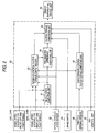
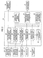
- Figs. 1 to 7 show an embodiment of the present invention, in which Fig. 1 is a schematic explanatory diagram of a vehicle driving force flow line and a center differential limiting control unit, Fig. 2 is a functional block diagram of the center differential limiting control unit, Fig. 3 is a functional block diagram of a feedback control clutch torque computing unit, Fig. 4 is an explanatory diagram showing an example of a basic value map of a vehicle speed and a front and rear axle control initiating differential speed, Fig. 5 is an explanatory diagram showing the example of a correction factor map of the front and rear axle control initiating differential speed based on a lateral acceleration, Fig. 6 is an explanatory diagram showing an example of clutch torque set by a feed forward control clutch torque computing unit, and Fig. 7 is an explanatory diagram showing an example of a tire diameter difference constant that is set according to an actual wheel speed difference among the four wheels.
- reference numeral 1 denotes an engine placed at a front part of a vehicle, and a driving force generated by the engine 1 is transmitted to a center differential 3 from an automatic transmission (shown as including a torque converter) behind the engine 1 by a transmission output shaft 2a.
- the driving force which exits the center differential 3 toward a rear wheel side, is then inputted into a rear final-drive differential 7 via a rear drive shaft 4, a propeller shaft 5 and a driving pinion 6, whereas the driving force which is directed toward a front wheel side is inputted into a front final-drive differential 11 via a transfer drive gear 8, a transfer driven gear 9, and a front drive shaft 10 which constitutes a drive pinion shaft portion.
- the automatic transmission 2, the center differential 3 and the front final-drive differential 11 are provided integrally within a case 12.
- the driving force inputted into the rear final-drive differential 7 is transmitted to a left rear wheel 14RL by a left drive shaft 13RL, while being transmitted to a right wheel 14RR by a right drive shaft 13RR.
- the driving force inputted into the front final-drive differential is transmitted to a left front wheel 14FL by a front left drive shaft 13FL, while being transmitted to a right front wheel 14FR by a front right drive shaft 13FR.
- a first sun gear 15 with a large diameter is formed on the input side transmission output shaft 2a of the center differential 3, and the first sun gear 15 meshes with a first pinion 16 with a small diameter, whereby a first gear train is constituted.
- a second sun gear 17 with a small diameter is formed on the rear drive shaft 4 which outputs the driving force toward the rear wheels, and the second sun gear 17 meshes with a second pinion 18 with a large diameter, whereby a second gear train is constituted.
- the first pinion 16 and the second pinion 18 are formed integrally on pinion members 19, respectively, and a plurality (for example, three) of the pinion members 19 are rotatably supported on a fixed shaft provided on a carrier 20. Then, the transfer drive gear 8 is coupled to a front end of the carrier 20 for transmitting to the front wheels.
- the transmission output shaft 2a is rotatably inserted into the carrier 20 from the front, whereas the rear drive shaft 4 is rotatably inserted into the carrier 20 from the rear, and the first sun gear 15 and the second sun gear 17 are installed in a space central within the carrier 20 . Then, the respective first pinions 16 and second pinions 18 on the plurality of pinion members 19 are both caused to mesh with the first sun gear 15 and the second sun gear 17, respectively.
- first and second pinions 16, 18 and the second sun gear 17 which constitute one output side and the carrier 20 of the first and second pinions 16, 18 which constitutes the other output side are meshed with the first sun gear 15 which constitutes an input side.
- the composite planetary-type center differential 3 provides a differential function by setting the numbers of teeth of the first and second sun gears 15, 17 and the plurality of first and second pinions 16, 18 that are disposed around circumferences of the sun gears 15, 17.
- a basic torque distribution is made to be a desired distribution (for example, an uneven torque distribution in which the driving torque is distributed heavily on the rear wheels) by setting appropriately meshing pitch radii of the first and second pinions 16, 18 with the first and second sun gears 15, 17, respectively.
- the center differential 3 allows a thrust load to remain without being cancelled by using, for example, helical gears for the first and second sun gears 15, 17 and the first and second pinion gears 16, 18, and allowing a helix angle between those of the first gear train and the second gear train to differ from each other. Furthermore, friction torques generated at ends of the pinion member 19 are set such that the friction torques are separated to the surface of the first and second pinions 16, 18 and the fixed shaft provided on the carrier 20 through meshing and are generated when a resultant force of a tangential loads is applied. Thus, by allowing a differential motion limiting torque proportional to an input torque to be obtained, the center differential 3 itself is also allowed to provide a differential motion limiting function.
- a center differential clutch (a transfer clutch) 21 which adopts a hydraulic multiple disc clutch provided between the two output members or the carrier 20 and the rear drive shaft 4 of the center differential 3 for varying the distribution of the driving force between the front and rear wheels 14FL, FR, RL, RR. Then, a torque distribution between the front and rear wheels 14FL, FR, RL, RR is allowed to be controlled to vary within a range from a four wheel drive in which the front and rear axles are directly coupled from a torque distribution ratio of 50/50 to the torque distribution ratio (of, for example, 35/65 front and rear) by controlling the engagement force of the transfer clutch 21.
- the transfer clutch 21 is connected to a center differential clutch driving unit 60 including a hydraulic circuit incorporating therein a plurality of solenoid valves, whereby the transfer clutch 21 is disengaged and engaged by a hydraulic pressure generated by the center differential clutch driving unit 60. Then, control signals (output signals directed to the respective solenoid valves) for driving the center differential clutch driving unit 60 are outputted from a center differential limiting control unit 50 as described below.
- the rear final-drive differential 7 includes a bevel gear type differential mechanism unit 22 and a rear differential clutch 23 which adopts a hydraulic multiple disc clutch for limiting a dif ferential motion between the left and right wheels.
- the rear differential clutch 23 is provided between a differential case 25 to which a ring gear 24 with which a drive pinion 6 is allowed to mesh is fixed and a rear wheel right drive shaft 13RR.
- the front final-drive differential 11 includes a bevel gear type differential mechanism unit 26 and a front differential clutch 27 which adopts the hydraulic multiple disc clutch for limiting the differential motion between the left and right wheels.
- the front differential clutch 27 is provided between a differential case 29 to which a ring gear 28 with which the drive pinion of the front drive shaft 10 is allowed to mesh is fixed and a front wheel right drive shaft 13FR.
- Signals are inputted into the center differential limiting control unit 50 from respective sensors as described below.
- wheel speeds of the respective wheels 14FL, 14FR, 14RL, 14RR are detected by wheel speed sensors 31FL, 31FR, 31RL, 31RR, respectively, and are then inputted into the center differential limiting control unit 50.
- a lateral acceleration Gy generated in the vehicle and an opening angle ⁇ th of a throttle valve of the engine are inputted into the center differential limiting control unit 50 from a lateral acceleration sensor 32 and the a throttle opening sensor 33, respectively.
- an ON-OFF signal from a brake switch 34 is also inputted into the center differential limiting control unit 50.
- ABS anti-lock brake system
- the center differential limiting control unit 50 has a micro computer and its peripheral circuit and includes, as shown in Fig. 2, mainly a vehicle speed computing unit 51, a feedback control clutch torque computing unit 52, a feed forward control clutch torque computing unit 53, a tire diameter difference computing unit 54 and a clutch torque computing unit 55.
- Wheel speeds ⁇ fl, ⁇ fr, ⁇ rl, ⁇ rr of the respective wheels 14FL, 14FR, 14RL, 14RR are inputted into the vehicle speed computing unit 51 from wheel speed sensors of the four wheels 14FL,FR,RL,RR or the respective wheel speed sensors 31FL, 31FR, 31RL, 31RR.
- the wheel speeds ⁇ fl, ⁇ fr, ⁇ rl, ⁇ rr of the respective wheels 14FL, 14FR, 14RL, 14RR, a lateral acceleration Gy, a brake switch signal and a vehicle speed V are inputted into the feedback control clutch torque computing unit 52 from the respective wheel speed sensors 31FL, 31FR, 31RL, 31RR, the lateral acceleration sensor 32, the brake switch, and the vehicle speed computing unit 51, respectively.
- the feedback control clutch torque computing unit 52 is such as to be provided as a feedback control clutch torque computing unit, and to be specific, as will be described later on, the feedback control clutch torque computing unit 52 computes a front and rear axle target differential speeds ⁇ ctrft, ⁇ ctrrt, a target front left and right wheel differential speed ⁇ Ftt, and a target rear left and right wheel differential speed ⁇ Rrt so as to compute front and rear axle differential speeds ⁇ ctrf, ⁇ ctrr, an actual front left and right wheel differential speed ⁇ Ft and an actual rear left and right wheel differential speed ⁇ Rr.
- a clutch torque Tlsdfb is computed by obtaining deviations ⁇ ctrf, ⁇ ctrr, ⁇ Ft, ⁇ Rr, with a switching function by using a polarity related to at least an integral term of each deviation, applying a sliding mode control, and furthermore, taking into a consideration of deviation amount which is proportional thereto.
- the feedback control clutch torque computing unit 52 includes mainly a brake switch delay processing unit 52a, an actual front and rear axle differential speed computing unit 52b, an actual front left and right wheel differential speed computing unit 52c, an actual rear left and right wheel differential speed computing unit 52d, a control initiating differential speed computing unit 52e, a target differential speed setting unit 52f, a sliding mode control clutch torque computing unit 52g, a deviation computing unit 52h and a feedback torque computing unit 52i.
- An ON-OFF signal is inputted into the brake switch delay processing unit 52a from the brake switch 34, and in order to prevent hunting, a predetermined short delay time is set when the brake switch 34 is switched from an ON state to an OFF state, whereby the brake switch 34 is put in the OFF state only after the delay time has elapsed when the brake switch 34 is switched from the ON state to the OFF state (note that no delay processing is implemented when the brake switch 34 is switched from the OFF state to the ON state).
- a brake switch signal processed at the brake switch delay processing unit 52a is outputted to the sliding mode control clutch torque computing unit 52g and the deviation computing unit 52h.
- the wheel speeds ⁇ fl, ⁇ fr, ⁇ rl, ⁇ rr of the respective wheels 14FL, 14FR, 14RL, 14RR are inputted into the actual front and rear axle differential speed computing unit 52b from the respective wheel speed sensors 31FL, 31FR, 31RL, 31RR, respectively.
- two types of actual front and rear axle differential speeds ⁇ ctrf, ⁇ ctrr are computed from the wheel speeds ⁇ fl, ⁇ fr, ⁇ rl, ⁇ rr so inputted using by the following equations (1), (2).
- ⁇ ctrf (( ⁇ fl+ ⁇ fr) - ( ⁇ rl+ ⁇ rr))/2
- ⁇ ctrr (( ⁇ rl+ ⁇ rr) - ( ⁇ fl+ ⁇ fr))/2
- the wheel speeds ⁇ fl, ⁇ fr of the left and right front wheels 14FL, 14FR and a lateral acceleration Gy are inputted into the actual front left and right wheel differential speed computing unit 52c from the wheel speed sensors 31FL, 31FR of the left and right front wheels 14FL, FR and the lateral acceleration sensor 32, and the actual front left and right wheel differential speed computing unit 52c then computes an actual differential speed ⁇ Ft according to turning conditions (including the condition in which the vehicle runs straight) of the vehicle by using any of the following equations (3), (4), and (5).
- a turning condition of the vehicle is determined by the lateral acceleration Gy: in the event that an absolute value
- the turning conditions of the vehicle can be determined by any other unit such as a yaw rate and a steering angle, and therefore, these are so determined.
- the wheel speeds ⁇ rl, ⁇ rr of the left and right rear wheels 14RL, 14RR and a lateral acceleration Gy are inputted into the actual rear left and right wheel differential speed computing unit 52d from the wheel speed sensors 31RL, 31RR of the left and right rear wheels and the lateral acceleration sensor 32. And the actual rear left and right wheel differential speed computing unit 52d then computes an actual differential speed ⁇ Rr according to turning conditions (including a condition in which the vehicle runs straight) of the vehicle by using any of the following equations (6), (7), and (8). At this time, the turning condition of the vehicle is determined by the lateral acceleration Gy as with the actual front left and right wheel differential speed computing unit 52c.
- the vehicle In the event that the absolute value
- the actual front and rear axle differential speed computing unit 52b, the actual front left and right wheel differential speed computing unit 52c and the actual rear left and right wheel differential speed computing unit 52d are provided as an actual differential speed detecting unit in the feedback control clutch torque computing unit.
- the lateral acceleration Gy and a vehicle speed V are inputted into the control initiating differential speed computing unit 52e from the lateral acceleration sensor 32 and the vehicle speed computing unit 51, respectively.
- the control initiating differential speed computing unit 52e then computes and sets a control initiating differential speed (a front and rear axle control initiating differential speed ⁇ ctrfs) which constitutes a lower limit value of an actual differential speed of the actual differential speed ⁇ ctrfs between the front and rear axles according to vehicle speed V and the lateral acceleration Gy while referring to a map set in advance.
- control initiating differential speed computing unit 52e also computes and sets a control initiating differential speed (a front and rear axle control initiating differential speed ⁇ ctrrs) which constitutes a lower limit value of the actualdifferentialspeed oftheactualdifferentialspeed ⁇ ctrrs between the front and rear axles while referring to the map set in advance.
- a control initiating differential speed (a front and rear axle control initiating differential speed ⁇ ctrrs) which constitutes a lower limit value of the actualdifferentialspeed oftheactualdifferentialspeed ⁇ ctrrs between the front and rear axles while referring to the map set in advance.
- control initiating differential speed computing unit 52e also sets certain values CFts, CRrs which have been set in advance as control initiating differential speeds (a front-wheel side control initiating differential speed ⁇ Fts, a rear-wheel side control initiating differential speed ⁇ Rrs) which constitutes lower limit values of the actual differential speeds ⁇ Ft between the left front wheel 14FL and the right front wheel 14FR and the actual differential speed ⁇ Rr between the left rear wheel 14RL and the right rear wheel 14RR, respectively.
- control initiating differential speeds a front-wheel side control initiating differential speed ⁇ Fts, a rear-wheel side control initiating differential speed ⁇ Rrs
- a basic value ⁇ ctrfsb of the front and rear axle control initiating differential speed ⁇ ctrfs on the basis of a current vehicle speed is obtained from a basic value map of vehicle speed and front and rear axle control initiating differential speed ⁇ trfs as shown in Fig. 4.
- a correction coefficient k ⁇ gy of the front and rear axle control initiating differential speed ⁇ ctrfs is obtained on the basis of a current lateral acceleration Gy from the map, as shown in Fig. 5, of correction coefficient of the front and rear axle control initiating differential speed ⁇ ctrfs on the basis of the lateral acceleration Gy.
- the front and rear axle control initiating differential speed ⁇ ctrrs is also set by the map as shown in Fig. 5 in which the front and rear axle control initiating differential speed ⁇ ctrrs is set so as to increase as the lateral acceleration Gy increases.
- the respective control initiating differential speeds ⁇ ctrfs, ⁇ ctrrs, ⁇ Fts, ⁇ Rrs are, as described below, the threshold values which determine an extent to which the differential limiting control is allowed to be implemented between the front and rear axles, the left and right front wheels and the left and right rear wheels.
- the engagement torque relative to the transfer clutch 21 is made to be 0.
- the differential speed that is actually to be controlledbecomes too small are, as described below, the threshold values which determine an extent to which the differential limiting control is allowed to be implemented between the front and rear axles, the left and right front wheels and the left and right rear wheels.
- the transfer clutch 21 is coupled in a stationary friction condition, and the control of the transfer clutch 21 is put in a slip-lock condition, whereby the convergence of the control becomes slow and the control stability is deteriorated.
- the control initiating differential speed is set in order to prevent the occurrence of the delayed convergence of the control, as well as the deteriorated control stability.
- the differential limiting control of the center differential is implemented without any delay, whereas in any other cases, the front differential clutch 27 and the rear differential clutch 23 are in normal operation, the differential limiting control of the center differential is controlled and set so as not to interfere with the control of the differentials.
- the same differential speed may be such as to be set by taking into consideration a torque that is inputted into the center differential 3 (a center differential input torque), or the front and rear axle control initiating differential speed ⁇ ctrfs may be set so as to be changed selectively according to the preference of the driver, the front and rear axle control initiating differential speed ⁇ ctrfs is designed to be set according to the vehicle speed V and the lateral acceleration Gy in this embodiment. Furthermore, depending on the specifications of the vehicle, the front and rear axle control initiating differential speed ⁇ ctrfs may be set according to only any of these parameters or a combination of a plurality of parameters (for example, a combination of the lateral acceleration Gy and the center differential input torque) or the same differential speed may be a constant value.
- the same differential speed may be such as to be set according to the vehicle speed V, the center differential input torque or the preference of the driver.
- the front and rear axle control initiating differential speed ⁇ ctrrs might be set according to only any of the parameters other than the lateral acceleration Gy or the combination of the plurality of parameters (for example, the combination of the lateral acceleration Gy and the center differential input torque), or the same differential speed may be the constant value.
- front-wheel side control initiating differential speed ⁇ Fts and the rear-wheel side control initiating differential speed ⁇ Rrs are designed to be set at the constant values in the embodiment, these may be set according to one of the other parameters which indicate the behaviour of the vehicle or a plurality of such parameters, as with the front and rear axle control initiating differential speeds ⁇ ctrfs, ⁇ ctrrs.
- the target differential speed setting unit 52f computes front and rear axle target differential speeds ⁇ ctrft, ⁇ trrt, a target front differential speed ⁇ Ftt and a target rear differential speed ⁇ Rrt on the basis of the respective control initiating differential speeds ⁇ ctrfs, ⁇ ctrrs, ⁇ Fts, ⁇ Rrs by using the following equations (9), (10), (11) and (12).
- Inputted into the sliding mode control clutch torque computing unit 52g are a delay-processed brake switch signal from the brake switch delay processing unit 52a, actual front and rear axle differential speeds ⁇ ctrf, ⁇ trr from the actual front and rear axle differential speed computing unit 52b, an actual differential speed ⁇ Ft between the left front wheel 14FL and the right front wheel 14 FR from the actual front left and right wheel differential speed computing unit 52c, an actual differential speed ⁇ Rr between the left rear wheel 14RL and the right rear wheel 14RR from the actual rear left and right wheel differential speed computing unit 52d, respective control initiating differential speeds ⁇ ctrfs, ⁇ trrs, ⁇ Fts, ⁇ Rrs from the target differential speed computing unit 52e, and respective target differential speeds ⁇ ctrft, ⁇ trrt, ⁇ Ftt, ⁇ Rrt from the target differential speed setting unit 52f.
- the sliding mode control clutch torque computing unit 52g computes a clutch torque of the transfer clutch 21 by obtaining a deviation between the target differential speed and the actual differential speed for each speed, with a switching function by using at least a polarity related to an integral term of the deviation so obtained and applying the sliding mode control.
- the deviation between the target differential speed and the actual differential speed for each speed can be computed as below.
- Differential speed deviation between the front and rear axle ⁇ ctrf ⁇ ctrf- ⁇ ctrft
- Differential speed deviation between the front and rear axle ⁇ ctrr ⁇ ctrr- ⁇ ctrrt
- Differential speed deviation between the left front wheel and the right front wheel ⁇ Ft ⁇ Ft- ⁇ Ftt
- Differential speed deviation between the left rear wheel and the right rear wheel ⁇ Rr ⁇ Rr- ⁇ Rrt
- clutch torques T SMCctrf, T SMCctrr, T SMCFt, T SMCRr applied to the transfer clutch 21 through a sliding mode control for each speed are computed by using the following switching function equations (17), (20), (23) and (26) .
- + ⁇ ) where, s ctrf ⁇ ctrf+ki• ⁇ ( ⁇ ctrf)dt (however, the integral range is from 0 to t) In addition, k wctrf is a differential term gain, and when (d ⁇ ctrf/dt)
- the clutch torque T SMCctrf is similarly made to be 0 and the integral value is also reset.
- + ⁇ ) where, s ctrr ⁇ ctrr+ki• ⁇ ( ⁇ ctrr)dt (however, the integral range is from 0 to t) In addition, k wctrr is a differential term gain, and when (d ⁇ ctrr/dt
- the clutch torque T SMCctrr is similarly made to be 0 and the integral value is also reset.
- + ⁇ ) where, s Ft ⁇ Ft+ki• ⁇ ( ⁇ Ft) dt (however, the integral range is from 0 to t)
- k wFt is the differential term gain, and when (d ⁇ Ft/dt)>0, it is made to be k wu, and when (d ⁇ Ft/dt) ⁇ 0, the differential term gain is made to be k wd.
- Jw is the inert
- + ⁇ ) where, s Rr ⁇ Rr+ki• ⁇ ( ⁇ Rr)dt (however, the integral range is from 0 to t)
- k wRr is the differential term gain, and when (d ⁇ Rr/dt)>0, it is made to be k wu, and when (d ⁇ Rr/dt) ⁇ 0, the differential term gain is made to be k wd.
- Jw is the inerti
- the switching function uses the polarity concerning the integral term of the deviation. Namely, in the switching function equation (18), the polarity concerning the integral term is obtained by dividing the integral term s ctrf by (
- ⁇ is also made to be a value which prevents a division by 0. Accordingly, even if values of the respective integral terms are small, irrespective of the smallness of the values, the values are used in implementing a sliding mode control so as to set the clutch torque, whereby it is possible to deal with a high response, thereby making it possible to realize a traction performance with a high accuracy and a good response.
- Inputted into the deviation control clutch torque computing unit 52h are a delay-processed brake switch signal from the brake switch delay processing unit 52a, actual front and rear axle differential speeds ⁇ ctrf, ⁇ trr from the actual front and rear axle differential speed computing unit 52b, an actual differential speed ⁇ Ft between thereof the left front wheel 14FL and the right front wheel 14 FR from the actual front left and right wheel differential speed computing unit 52c, an actual differential speed ⁇ Rr between the left rear wheel 14RL and the right rear wheel 14RR from the actual rear left and right wheel differential speed computing unit 52d, respective control initiating differential speeds ⁇ ctrfs, ⁇ trrs, ⁇ Fts, ⁇ Rrs from the target differential speed computing unit 52e, and respective target differential speeds ⁇ ctrft, ⁇ trrt, ⁇ Ftt, ⁇ Rrt from the target differential speed setting unit 52f .
- the deviation torque computing unit 52h obtains a deviation between the target differential speed and the actual differential speed for each speed and computes proportional components of the clutch torque (clutch torques T pcctrf, T pctrr, T pcFt, TpcRf) which allow the actual differential speed to converge on the target differentialspeedaccordingtothedeviationsoobtained.
- the deviation between the target differential speed and the actual differential speed for each speed can be computed as below.
- Differential speed deviation between the front and rear axle ⁇ pctrf ⁇ ctrf- ⁇ ctrft - ( ⁇ ctrft- ⁇ ctrfs)
- Differential speed deviation between the front and rear axle ⁇ pctrr ⁇ ctrr- ⁇ ctrrt - ( ⁇ ctrrt- ⁇ ctrrs)
- Differential speed deviation between the left rear wheel and the right rear wheel ⁇ pRr ⁇ Rr- ⁇ Rrt - ( ⁇ Rrt- ⁇ Rrs)
- the respective clutch torques T pcctrf, T pcctrr, T pcFt and T pcRr provided by the deviation control are set at 0 when the ON signal is inputted from the brake switch so as to avoid the interference with the brake condition produced by the singal.
- Inputted into the feedback control clutch torque computing and outputting unit 52i are respective clutch torques T SMCctrf, T SMCctrr, T SMCFt and T SMCRr from the sliding mode control clutch torque computing unit 52g and respective clutch torques T pcctrf, T pcctrr, T pcFt and T pcRr from the deviation control clutch torque computing unit 52h.
- T ctrf T SMCctrf + T pcctrf
- T ctrr T SMCctrr + T pcFt
- Ft T SMCFt + T pcFt
- Rr T SMCRr + T pcRr
- T lsdfb MAX (T ctrf, T ctrr, T Ft, T Rr)
- the sliding mode control clutch torque computing unit 52g, the deviation control clutch torque computing unit 52h, and the feedback control clutch torque computing and outputting unit 52i are provided as a clutch torque computing and outputting unit in the feedback control clutch torque computing unit.
- a throttle opening ⁇ th and an ON-OFF signal are inputted into the feed forward control clutch torque computing unit 53 from the throttle opening sensor 33 and the brake switch 34, respectively.
- the feed forward control clutch torque computing unit 53 computes and sets a clutch torque according to the throttle opening ⁇ th while referring to the map (for example, Fig. 6) which is set in advance through experiments as the clutch torque T lsdff that is to be provided to the transfer clutch 21 through the feed forward control and then outputs the clutch torque T lsdff to the clutch torque computing unit 55.
- corrections may be implemented by the lateral acceleration Gy, the vehicle speed V, and the actual front and rear axle differential speeds ⁇ trf, ⁇ ctrr so that the clutch torque T lsdff can be obtained through a more accurate feed forward control.
- the clutch torque T lsdff which is computed through the feed forward control as described above is then outputted to the clutch torque computing unit 55.
- the feed forward clutch torque computing unit 53 is provided as a feed forward control clutch torque computing unit.
- Inputted into the tire diameter difference computing unit 54 are the lateral acceleration Gy from the lateral acceleration sensor 32, the vehicle speed V from the vehicle speed computing unit 51, the actual front and rear axle differential speeds ⁇ ctrf, ⁇ ctrr from the actual front and rear axle differential speed computing unit 52b of the feedback control clutch torque computing unit 52, the front actual left and right wheel differential speed ⁇ Ft from the actual front left and right wheel differential speed computing unit 52c, and the rear actual left and right wheel differential speed ⁇ Rr from the rear actual left and right wheel differential speed computing unit 52d.
- the tire diameter difference computing unit 54 sets, while referring to the map set in advance, a tire diameter difference constant Rtr from a largest one ( ⁇ ) of the actual front and rear axle differential speeds ⁇ ctrf, ⁇ ctrr, a front actual left and right wheel differential speed ⁇ Ft and a rear actual left and right wheel differential speed ⁇ cRr which result when a pre set condition is established when the vehicle runs substantially straight and that the slippage is unlikely to occur on the four wheel.
- the above determinated condition is such that the absolute value of the lateral acceleration Gy is 0.1g or smaller and the vehicle speed is 20km/h or slower.
- a tire diameter difference constant Rtr is set by referring to the map shown in Fig. 7 which shows a relationship between the actual differential speed ⁇ and the tire diameter difference constant Rtr.
- the tire diameter difference constant Rtr is set to be in the vicinity of 0.5 in the event that the actual differential speed ⁇ is extremely small, and is set so as to decrease gradually as the tire diameter difference constant Rtr increases.
- the diameter difference of the tire is determined to be small, whereas as the tire diameter difference constant Rtr decreases from 0.5, the diameter difference of the tire is determined to be large. Note that when used in this embodiment, the diameter difference of the tire is evaluated collectively from the four wheels.
- the tire diameter difference constant Rtr is set to a value that was set previously without computing the tire diameter difference constant Rtr or without updating the value that was set previously.
- the reason for this setting is that where the absolute value of the lateral acceleration Gy is larger than 0.1g, whether or not the rotational difference is taking place due to the tire diameter difference when, for example, the vehicle is cornering, and where the vehicle speed V is faster than 20km/h, the slippage of the tire is easily permitted, and therefore whether or not the rotational difference is taking place due to the tire diameter difference.
- the tire diameter difference constant Rtr which is set as described above is then outputted to the clutch torque computing unit 55.
- the tire diameter difference computing unit 54 is provided as the tire diameter difference computing unit.
- Inputted into this clutch torque computing unit 55 are respectively the ON-OFF signal from the brake switch 34, an ON-OFF signal from the ABS control unit 35, the clutch torque T lsdfb from the feedback control clutch torque computing unit 52 which results from the feedback control, the clutch torque T lsdff from the feed forward control clutch torque computing unit 53 which results from the feed forward control and the tire diameter difference constant Rtr from the tire diameter difference computing unit 54.
- the clutch torque computing unit 55 computes a final clutch torque T lsd that is to be outputted to the transfer clutch 21 from the following equation (34) and outputs the torque so computed to the center differential clutch driving unit 60.
- T lsd Rtr•T lsdff + (1-Rtr)•T lsdfb
- the clutch torque T lsd is made to be a constant value CABS that has been set in advance in order to prevent the interference with the ABS control.
- the clutch torque T lsd is made to be a constant value Cbrk set in advance in order topreventtheinterferencewithabrake-appliedcondition so produced.
- the ratio of the clutch torque obtained through the feedback control and the clutch torque obtained through the feed forward control is changed according to the diameter difference of the tires so as to compute the final clutch torque.
- the clutch torque can be set appropriately by reflecting the diameter difference of the tire to the clutch torque obtained through the feed forward control, the slippage can also be avoided while suppressing the occurrence of the internal circulating torque, as well as the tight corner braking phenomenon.
- the feedback control clutch torque computing unit 52 computes the four clutch torques T ctrf, T ctrr, T Ft and T Rr such that the maximum value of the clutch torques so computed becomes the clutch torque T lsdfb provided through the feedback control, depending on the specifications of the vehicle, all of the four clutch torques do not have to be obtained but any one or some of the four clutch torques may be obtained so that the clutch torque that would be provided through the feedback control can be obtained from them.
- the respective clutch torques T pcctrf, T pcctrr, T pcFt and T pcRr from the deviation computing unit 52h are added to the respective clutch torques T SMCctrf, T SMCctrr, T SMCFt and T SMCRt from the sliding mode control clutch torque computing unit 52g so as to obtain the final four clutch torques T ctrf, T ctrr, T Ft and T Rr, for the vehicle that is not largely affected by the respective clutch torques T pcctrf, T pcctrr, T pcFt and T pcRr from the deviation computing unit 52h, the clutch torque T lsdfb that would be provided through the feedback control may be obtained only by using the respective clutch torques T SMCctrf, T SMCctrr, T SMCFt and T SMCRt from
- tire diameter difference constant Rtr is illustrated as being set in the range from the vicinity of 0.5 to a smaller value, depending on the specifications of the vehicle, the tire diameter difference constant Rtr may be set in ranges other than the one described above.
- the tire diameter difference constant Rtr is computed on the basis of the front actual left and right wheel differential speed ⁇ Ft, and in the event that the same is applied to the rear differential clutch 23, the tire diameter difference constant Rtr is computed on the basis of the rear actual left and right wheel differential speed ⁇ Rr.
- the slippage can also be suppressed effectively while avoiding the occurrence of the internal circulating torque.
Landscapes
- Engineering & Computer Science (AREA)
- Mechanical Engineering (AREA)
- General Engineering & Computer Science (AREA)
- Chemical & Material Sciences (AREA)
- Combustion & Propulsion (AREA)
- Transportation (AREA)
- Physics & Mathematics (AREA)
- Fluid Mechanics (AREA)
- Arrangement And Driving Of Transmission Devices (AREA)
- Arrangement And Mounting Of Devices That Control Transmission Of Motive Force (AREA)
- Hydraulic Clutches, Magnetic Clutches, Fluid Clutches, And Fluid Joints (AREA)
Applications Claiming Priority (2)
| Application Number | Priority Date | Filing Date | Title |
|---|---|---|---|
| JP2002278131 | 2002-09-24 | ||
| JP2002278131A JP4294286B2 (ja) | 2002-09-24 | 2002-09-24 | 車両の差動制限制御装置 |
Publications (3)
| Publication Number | Publication Date |
|---|---|
| EP1403124A2 true EP1403124A2 (de) | 2004-03-31 |
| EP1403124A3 EP1403124A3 (de) | 2006-08-02 |
| EP1403124B1 EP1403124B1 (de) | 2008-07-16 |
Family
ID=31973260
Family Applications (1)
| Application Number | Title | Priority Date | Filing Date |
|---|---|---|---|
| EP03255996A Expired - Lifetime EP1403124B1 (de) | 2002-09-24 | 2003-09-24 | Steuerungseinrichtung zur Differentialbegrenzung für ein Fahrzeug und Verfahren dafür |
Country Status (4)
| Country | Link |
|---|---|
| US (1) | US7613558B2 (de) |
| EP (1) | EP1403124B1 (de) |
| JP (1) | JP4294286B2 (de) |
| DE (1) | DE60322160D1 (de) |
Cited By (5)
| Publication number | Priority date | Publication date | Assignee | Title |
|---|---|---|---|---|
| EP1610023A1 (de) * | 2004-06-21 | 2005-12-28 | AISIN AI Co., Ltd. | Mehrfachkupplungsgetriebe |
| WO2006100585A1 (en) * | 2005-03-25 | 2006-09-28 | Ferrari S.P.A. | Motor vehicle with insertable four-wheel drive |
| EP1886864A1 (de) * | 2006-08-04 | 2008-02-13 | GM Global Technology Operations, Inc. | Methode zur Steuerung der Drehmomentübertragungsrichtung in einem Differential mit begrenztem Schlupf |
| WO2010094877A1 (fr) * | 2009-02-20 | 2010-08-26 | Renault S.A.S. | Procede de commande d'une difference de vitesse entre roues avant et arriere d'un vehicule a quatre roues motrices |
| EP1740432A4 (de) * | 2004-04-19 | 2011-03-23 | Magna Powertrain Usa Inc | Auf einem modell basierende steuerung für ein drehmomentverteilungssystem |
Families Citing this family (23)
| Publication number | Priority date | Publication date | Assignee | Title |
|---|---|---|---|---|
| US6882922B2 (en) * | 2000-10-11 | 2005-04-19 | Visteon Global Technologies, Inc. | Torque-biasing system |
| JP4263448B2 (ja) | 2002-09-24 | 2009-05-13 | 富士重工業株式会社 | 車両の差動制限制御装置 |
| US7526380B2 (en) * | 2003-12-02 | 2009-04-28 | Gmv Aerospace And Defence, S.A. | Method and system to provide a global multiuser service of localization information with integrity as required under liability or commercial issues |
| US7578333B2 (en) * | 2004-07-20 | 2009-08-25 | Pregis Corporation | Machine and methods for the manufacture of air-filled cushions |
| JP2006176022A (ja) * | 2004-12-22 | 2006-07-06 | Fuji Heavy Ind Ltd | 四輪駆動車の動力伝達装置 |
| US7458911B2 (en) | 2005-02-02 | 2008-12-02 | Dana Automotive Systems Group, Llc | Drive system for motor vehicle |
| US7966113B2 (en) * | 2005-08-25 | 2011-06-21 | Robert Bosch Gmbh | Vehicle stability control system |
| US7641014B2 (en) * | 2006-01-31 | 2010-01-05 | Robert Bosch Gmbh | Traction control system and method |
| DE102006038358B4 (de) * | 2006-08-09 | 2009-01-15 | Getrag Driveline Systems Gmbh | Achsantriebseinheit für einen Antriebsstrang |
| DE102007038151A1 (de) * | 2007-08-13 | 2009-02-19 | Magna Powertrain Ag & Co Kg | Verfahren zum Nachjustieren eines Aktuators einer Allradkupplung |
| JP4949280B2 (ja) * | 2008-01-21 | 2012-06-06 | 富士重工業株式会社 | 4輪駆動車の異常検出装置 |
| JP4463311B2 (ja) * | 2008-03-21 | 2010-05-19 | 住友ゴム工業株式会社 | タイヤ空気圧低下検出方法及び装置、並びにタイヤ減圧判定のプログラム |
| DE102008050214B4 (de) * | 2008-10-02 | 2021-06-17 | Audi Ag | Verfahren zum Betreiben eines Allradantriebs eines Kraftfahrzeugs und Allradantriebssystem |
| JP4866452B2 (ja) * | 2009-08-05 | 2012-02-01 | 本田技研工業株式会社 | 四輪駆動車両のトルク配分制御装置 |
| US9605740B2 (en) * | 2009-10-01 | 2017-03-28 | Ford Global Technologies, Llc | Control of an electronic locking differential |
| US9108518B2 (en) * | 2013-06-11 | 2015-08-18 | Electro-Motive Diesel, Inc. | Axle torque control corresponding to wheel sizes |
| JP6216666B2 (ja) * | 2014-03-12 | 2017-10-18 | 株式会社ジェイテクト | 駆動力配分制御装置 |
| DE102017203362A1 (de) * | 2017-03-01 | 2018-09-06 | Audi Ag | Einstellen einer Drehmomentverteilung zwischen Rädern einer Achse eines Kraftfahrzeugs durch Betätigen einer Bedieneinheit |
| CN107450308B (zh) * | 2017-06-21 | 2020-05-05 | 合肥中导机器人科技有限公司 | 存储设备、机器人 |
| KR102461507B1 (ko) * | 2017-09-25 | 2022-11-02 | 현대자동차주식회사 | 차량용 클러치 버스트 방지방법 |
| DE102017219271A1 (de) * | 2017-10-26 | 2019-05-02 | Deere & Company | Verfahren zum Betreiben eines Nutzfahrzeugs mit Allradantrieb und Differentialsperre |
| IT201900017531A1 (it) * | 2019-09-30 | 2021-03-30 | Ferrari Spa | Metodo di controllo di un veicolo stradale con un microslittamento della frizione |
| CN115639853B (zh) * | 2022-09-14 | 2025-06-10 | 徐工消防安全装备有限公司 | 一种电流平衡差速控制方法及高空作业平台 |
Family Cites Families (29)
| Publication number | Priority date | Publication date | Assignee | Title |
|---|---|---|---|---|
| US4772552A (en) | 1984-04-23 | 1988-09-20 | Dana-Farber Cancer Institute, Inc. | Monoclonal antibody which recognizes a 200-220 KD antigen on natural killer cells |
| SE8403935L (sv) | 1984-08-01 | 1986-02-02 | Larsson Ralf Ide Prod | Anordning for fordelning av finfordelat material pa en yta |
| US4713596A (en) | 1985-07-10 | 1987-12-15 | General Electric Company | Induction motor drive system |
| US4989686A (en) * | 1988-07-07 | 1991-02-05 | Borg-Warner Automotive, Inc. | System for controlling torque transmission in a four wheel drive vehicle |
| US5079708A (en) | 1989-03-24 | 1992-01-07 | Brown Jack L | Road vehicle cornering assistance mechanism |
| JPH0814294B2 (ja) | 1989-07-03 | 1996-02-14 | 日産自動車株式会社 | 4輪駆動車の駆動力配分制御装置 |
| JP2768134B2 (ja) | 1992-05-20 | 1998-06-25 | 日産自動車株式会社 | 四輪駆動車の駆動力配分制御装置 |
| US6000488A (en) * | 1992-06-24 | 1999-12-14 | Borg-Warner Automotive, Inc. | Motor vehicle transfer case |
| JP3416970B2 (ja) | 1993-01-19 | 2003-06-16 | 日産自動車株式会社 | 車両のヨーイング運動量制御装置 |
| US5809443A (en) | 1994-12-09 | 1998-09-15 | Ford Motor Company | Four-wheel drive transfer case controller with compensation for tires with different diameters |
| JP3409537B2 (ja) | 1995-10-19 | 2003-05-26 | 日産自動車株式会社 | 車両の四輪駆動制御装置 |
| JPH09123778A (ja) | 1995-10-31 | 1997-05-13 | Nissan Motor Co Ltd | 車両の四輪駆動制御装置 |
| JP3405052B2 (ja) | 1996-03-21 | 2003-05-12 | 日産自動車株式会社 | 駆動力配分制御装置 |
| JP3473363B2 (ja) | 1997-02-27 | 2003-12-02 | 株式会社デンソー | システム制御装置 |
| US6047231A (en) * | 1997-06-06 | 2000-04-04 | Ford Global Technologies, Inc. | Four wheel drive transfer case controller compatible with a spare tire |
| US5979584A (en) * | 1997-07-25 | 1999-11-09 | Ford Global Technologies, Inc. | Four-wheel drive transfer case controller |
| DE19810033A1 (de) * | 1998-03-09 | 1999-09-16 | Mannesmann Sachs Ag | Anordnung zur Überwachung des Verschleißzustandes einer Reibungskupplung |
| JP3822753B2 (ja) | 1998-07-07 | 2006-09-20 | トヨタ自動車株式会社 | 車輌の車輪速度制御方法 |
| JP3339573B2 (ja) | 1999-11-01 | 2002-10-28 | 株式会社ユニシアジェックス | スライディングモード制御システムの診断装置 |
| DE10054600A1 (de) | 1999-11-04 | 2001-06-13 | Unisia Jecs Corp | Vorrichtung und Verfahren für eine Gleitmodusregelung |
| JP3723028B2 (ja) * | 1999-12-28 | 2005-12-07 | 本田技研工業株式会社 | 路面勾配検出装置及び発進クラッチの制御装置 |
| JP2001330140A (ja) * | 2000-05-22 | 2001-11-30 | Toyota Motor Corp | 車両用クラッチの制御装置 |
| JP4921632B2 (ja) * | 2000-05-31 | 2012-04-25 | 日本精工株式会社 | 四輪駆動車における前後輪変速装置 |
| US6498974B1 (en) * | 2000-06-28 | 2002-12-24 | Ford Global Tech., Inc. | Method for controlling a transfer case which utilizes a proportional and an integral control component |
| JP4237378B2 (ja) * | 2000-06-29 | 2009-03-11 | 富士重工業株式会社 | 車両の駆動力伝達制御装置 |
| JP2002031224A (ja) * | 2000-07-17 | 2002-01-31 | Hitachi Ltd | 自動変速機の制御方法、および自動変速機の制御装置 |
| US6575870B2 (en) * | 2000-07-21 | 2003-06-10 | Honda Giken Kogyo Kabushiki Kaisha | Driving force control system for front-and-rear wheel drive vehicles |
| JP3525879B2 (ja) | 2000-09-19 | 2004-05-10 | 日産自動車株式会社 | 4輪駆動車の前後輪トルク配分制御装置 |
| JP2002161797A (ja) | 2000-11-24 | 2002-06-07 | Unisia Jecs Corp | スライディングモード制御装置 |
-
2002
- 2002-09-24 JP JP2002278131A patent/JP4294286B2/ja not_active Expired - Fee Related
-
2003
- 2003-09-23 US US10/667,396 patent/US7613558B2/en not_active Expired - Fee Related
- 2003-09-24 DE DE60322160T patent/DE60322160D1/de not_active Expired - Lifetime
- 2003-09-24 EP EP03255996A patent/EP1403124B1/de not_active Expired - Lifetime
Cited By (12)
| Publication number | Priority date | Publication date | Assignee | Title |
|---|---|---|---|---|
| EP1740432A4 (de) * | 2004-04-19 | 2011-03-23 | Magna Powertrain Usa Inc | Auf einem modell basierende steuerung für ein drehmomentverteilungssystem |
| EP1610023A1 (de) * | 2004-06-21 | 2005-12-28 | AISIN AI Co., Ltd. | Mehrfachkupplungsgetriebe |
| US7252621B2 (en) | 2004-06-21 | 2007-08-07 | Aisin Ai Co., Ltd. | Transmission having plural clutches |
| US7399256B2 (en) | 2004-06-21 | 2008-07-15 | Aisin Ai Co., Ltd. | Transmission having plural clutches |
| WO2006100585A1 (en) * | 2005-03-25 | 2006-09-28 | Ferrari S.P.A. | Motor vehicle with insertable four-wheel drive |
| US8364360B2 (en) | 2005-03-25 | 2013-01-29 | Ferrari S.P.A. | Motor vehicle with insertable four-wheel drive |
| EP1886864A1 (de) * | 2006-08-04 | 2008-02-13 | GM Global Technology Operations, Inc. | Methode zur Steuerung der Drehmomentübertragungsrichtung in einem Differential mit begrenztem Schlupf |
| WO2010094877A1 (fr) * | 2009-02-20 | 2010-08-26 | Renault S.A.S. | Procede de commande d'une difference de vitesse entre roues avant et arriere d'un vehicule a quatre roues motrices |
| FR2942430A1 (fr) * | 2009-02-20 | 2010-08-27 | Renault Sas | Procede de commande d'une difference de vitesse entre roues avant et arriere d'un vehicule a quatre roues motrices. |
| CN102325666A (zh) * | 2009-02-20 | 2012-01-18 | 雷诺股份公司 | 控制四轮驱动车辆的前轮和后轮间的速度差的方法 |
| US8670910B2 (en) | 2009-02-20 | 2014-03-11 | Renault S.A.S. | Method for controlling a speed difference between the front wheels and rear wheels of a four-wheel drive vehicle |
| CN102325666B (zh) * | 2009-02-20 | 2014-12-10 | 雷诺股份公司 | 控制四轮驱动车辆的前轮和后轮间的速度差的方法 |
Also Published As
| Publication number | Publication date |
|---|---|
| DE60322160D1 (de) | 2008-08-28 |
| EP1403124B1 (de) | 2008-07-16 |
| US20040059494A1 (en) | 2004-03-25 |
| US7613558B2 (en) | 2009-11-03 |
| EP1403124A3 (de) | 2006-08-02 |
| JP2004114765A (ja) | 2004-04-15 |
| JP4294286B2 (ja) | 2009-07-08 |
Similar Documents
| Publication | Publication Date | Title |
|---|---|---|
| EP1403124B1 (de) | Steuerungseinrichtung zur Differentialbegrenzung für ein Fahrzeug und Verfahren dafür | |
| US7386383B2 (en) | Differential limiting control apparatus for a vehicle and the method thereof | |
| US5168955A (en) | Traction control system for four-wheel drive vehicle | |
| EP1203688B1 (de) | Antriebskraftverteilungssystem eines Fahrzeugs | |
| US6708088B2 (en) | Vehicle behavior control apparatus | |
| EP1538017B1 (de) | Kraftübertragung für ein Fahrzeug mit Allradantrieb | |
| EP0314452B1 (de) | Kraftübertragung für ein Fahrzeug mit Allradantrieb | |
| EP1686031B1 (de) | Steuervorrichtung eines Fahrzeuges mit Allradantrieb | |
| EP0314453B1 (de) | Zugkraftsteuerungssystem für ein vierradgetriebenes Kraftfahrzeug | |
| US6587775B2 (en) | Driving force control system for four-wheel drive vehicles | |
| EP1388453B1 (de) | Steuerungsvorrichtung und -verfahren für Fahrzeug mit Vierradantrieb | |
| US6145614A (en) | Four-wheel drive vehicle having differential-limiting control | |
| EP1400390A2 (de) | Antriebskraftverteilungs- Steuerungsgerät für ein vierradgetriebenes Fahrzeug | |
| EP1342608B1 (de) | Steuersystem zur Antriebskraftübertragung für ein Kraftfahrzeug und Verfahren dafür | |
| EP0415554B1 (de) | Steuerung der Drehmomentverteilung für ein Kraftfahrzeug mit Allradantrieb | |
| EP0421594A1 (de) | Steuerung der Verteilung des Drehmomentes für ein Kraftfahrzeug mit Allradantrieb | |
| EP1388454A2 (de) | Antriebskraft- Verteilungssteuervorrichtung und Steuerungsverfahren | |
| JP4263459B2 (ja) | 車両の差動制限制御装置 | |
| JP2002114049A (ja) | 車両用駆動力配分装置 | |
| JP4000438B2 (ja) | 車両用差動制限装置 | |
| EP1500547A1 (de) | Vorrichtung und verfahren zur steuerung der verteilung von antriebskraft eines kraftfahrzeugs mit vierradantrieb |
Legal Events
| Date | Code | Title | Description |
|---|---|---|---|
| PUAI | Public reference made under article 153(3) epc to a published international application that has entered the european phase |
Free format text: ORIGINAL CODE: 0009012 |
|
| AK | Designated contracting states |
Kind code of ref document: A2 Designated state(s): AT BE BG CH CY CZ DE DK EE ES FI FR GB GR HU IE IT LI LU MC NL PT RO SE SI SK TR |
|
| AX | Request for extension of the european patent |
Extension state: AL LT LV MK |
|
| PUAL | Search report despatched |
Free format text: ORIGINAL CODE: 0009013 |
|
| AK | Designated contracting states |
Kind code of ref document: A3 Designated state(s): AT BE BG CH CY CZ DE DK EE ES FI FR GB GR HU IE IT LI LU MC NL PT RO SE SI SK TR |
|
| AX | Request for extension of the european patent |
Extension state: AL LT LV MK |
|
| AKX | Designation fees paid | ||
| 17P | Request for examination filed |
Effective date: 20061129 |
|
| RBV | Designated contracting states (corrected) |
Designated state(s): DE |
|
| REG | Reference to a national code |
Ref country code: DE Ref legal event code: 8566 |
|
| 17Q | First examination report despatched |
Effective date: 20070425 |
|
| GRAP | Despatch of communication of intention to grant a patent |
Free format text: ORIGINAL CODE: EPIDOSNIGR1 |
|
| GRAS | Grant fee paid |
Free format text: ORIGINAL CODE: EPIDOSNIGR3 |
|
| GRAA | (expected) grant |
Free format text: ORIGINAL CODE: 0009210 |
|
| AK | Designated contracting states |
Kind code of ref document: B1 Designated state(s): DE |
|
| REF | Corresponds to: |
Ref document number: 60322160 Country of ref document: DE Date of ref document: 20080828 Kind code of ref document: P |
|
| PLBE | No opposition filed within time limit |
Free format text: ORIGINAL CODE: 0009261 |
|
| STAA | Information on the status of an ep patent application or granted ep patent |
Free format text: STATUS: NO OPPOSITION FILED WITHIN TIME LIMIT |
|
| 26N | No opposition filed |
Effective date: 20090417 |
|
| PGFP | Annual fee paid to national office [announced via postgrant information from national office to epo] |
Ref country code: DE Payment date: 20160920 Year of fee payment: 14 |
|
| REG | Reference to a national code |
Ref country code: DE Ref legal event code: R082 Ref document number: 60322160 Country of ref document: DE Representative=s name: VOSSIUS & PARTNER PATENTANWAELTE RECHTSANWAELT, DE Ref country code: DE Ref legal event code: R081 Ref document number: 60322160 Country of ref document: DE Owner name: SUBARU CORPORATION, JP Free format text: FORMER OWNER: FUJI JUKOGYO K.K., TOKIO/TOKYO, JP |
|
| REG | Reference to a national code |
Ref country code: DE Ref legal event code: R119 Ref document number: 60322160 Country of ref document: DE |
|
| PG25 | Lapsed in a contracting state [announced via postgrant information from national office to epo] |
Ref country code: DE Free format text: LAPSE BECAUSE OF NON-PAYMENT OF DUE FEES Effective date: 20180404 |