EP1403674A2 - Einstellbares Pinhole - Google Patents
Einstellbares Pinhole Download PDFInfo
- Publication number
- EP1403674A2 EP1403674A2 EP03020426A EP03020426A EP1403674A2 EP 1403674 A2 EP1403674 A2 EP 1403674A2 EP 03020426 A EP03020426 A EP 03020426A EP 03020426 A EP03020426 A EP 03020426A EP 1403674 A2 EP1403674 A2 EP 1403674A2
- Authority
- EP
- European Patent Office
- Prior art keywords
- pinhole
- adjustable
- another
- edges
- foils
- Prior art date
- Legal status (The legal status is an assumption and is not a legal conclusion. Google has not performed a legal analysis and makes no representation as to the accuracy of the status listed.)
- Granted
Links
Images


Classifications
-
- G—PHYSICS
- G02—OPTICS
- G02B—OPTICAL ELEMENTS, SYSTEMS OR APPARATUS
- G02B5/00—Optical elements other than lenses
- G02B5/005—Diaphragms
Definitions
- the task is to develop a high-precision pinhole that can be closed light-tight and whose opening has a square shape from size zero.
- this problem is solved in that an arrangement of film edges, the edges of which point towards the pinhole opening are preferably ground, are moved relative to one another in accordance with the inventive embodiments.
- the design of the pinhole opening from film edges offers the decisive advantage that the corners of the pinhole opening are completely sharp and the radius of curvature of the corners is zero. This allows pinhole openings to be reproducibly set from size zero.
- the film edges can already be prefabricated with high precision, for example by cutting with diamond cutting or by laser cutting or by etching. For preferred movement, which should run very precisely and without play, solid-state joints in the form of elastic webs are provided, on which tilting or rotation takes place.
- the invention surprisingly allows an adjustable and reproducible reduction in the size of the pinhole opening from size zero and its light-tight closure without risk of collision between the film edges.
- the invention is explained below with reference to the schematic drawings.
- the foil material can be, for example, spring steel, spring bronze or aluminum with a thickness of, for example, 10 ⁇ m.
- the film edges can be ground in a composite, for example 100 prefabricated individual films, punched and then separated again or used as a strip material in the delivery state.
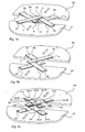
- connection points V1, V2 show schematically an image of L-shaped film pieces F1-F4 arranged at a preferably right angle, F1 and F2 as well as F3 and F4 being firmly connected to one another at connection points V1, V2. They are fixed at their ends facing away from the connection points (black marked s) on base plates P1 and P2 which can be displaced in the direction of the arrow, on each plate such that the pinhole opening opens punctually when the plates P1 and P2 are moved synchronously in the direction of the arrow and closes
- the foils can be connected to one another and to the plates P1 and P2, for example by gluing, resistance welding, diffusion welding or ultrasonic welding.
- the opening area between the film edges connected at points V1, V2 is reduced or enlarged, namely when the plates P1, P2 approach, the pinhole PH is opened and vice versa.
- the pinhole opening closes preferably square to a point. If the distance between the plates P1, P2 is increased further, the pinhole opening is covered in a light-tight manner without the film edges being able to hinder or damage one another.
- FIG. 1b shows a further variant of the invention. It consists of cross-shaped, cross-shaped foil edges F5-F8, each of which is attached to the plates P1 (F5, F6) or P2 (F7, F8), two plates P1, P2 again being displaceable in the direction of the arrow, but here when approaching from P1, P2 the pinhole PH closes and vice versa, because F5-F8 and F6-F7 slide over each other like scissors because they are not connected to each other.
- the opening of the pinhole is formed here by the corners of the foil arrangements facing away from the plate edges.
- FIG. 1c A further variant of the invention is shown in FIG. 1c.
- Each of the film edges F9, F10, F11, F12 has two joints, preferably solid joints.
- the distance between the articulation points G91 to G92, G101 to G102, G111 to G112 and G121 to G122 is preferably the same and much larger than the pinhole opening.
- the pairs of foils F9, F11 and F10, F12 are each L-shaped at their connection points V3 and V4 and attached in a cross shape on the plates P1, P2 so that when the plates P1 and P2 are opened synchronously in the direction of the arrow, the pinhole opening closes punctually and preferably square and vice versa.
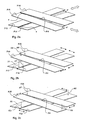
- Fig. 2 a new embodiment is shown, wherein two foil edges F13, F14, F15, F16 in pairs are slightly V-shaped to each other, ie enclose a small angle to each other.
- the one pair of foils to the other with respect to its center axis between the individual foils, preferably displaced synchronously to one another in the direction of the arrow.
- a vertical displacement to one another preferably by synchronous movement of the two pairs of foils via two motors (not shown), results in large travel ranges when setting the pinhole opening with high accuracy, so that it is possible to dispense with position measuring systems.
- Fig. 2 a new embodiment is shown, wherein two foil edges F13, F14, F15, F16 in pairs are slightly V-shaped to each other, ie enclose a small angle to each other.
- the one pair of foils to the other with respect to its center axis between the individual foils, preferably displaced synchronously to one another in the direction of the arrow.
- the slightly V-shaped opening angle between the film edges is varied in that the films F17 and F18 about the axes A1 and A2 and the films F19 and F20 about the axes A3 and A4 are rotated in opposite directions and preferably synchronously with the opening and closing of the pinhole opening become.
- the axes of rotation A5, A6 and A7, A8 are on the opposite sides of the pairs of foils F21, F22 and F23, F24.
- the films are preferably rotated synchronously and in the same direction.
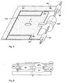
- FIG. 3 shows an arrangement for pinhole adjustment, which relates to the arrangement of the film edges according to FIG. 1a.
- the displacement of the plates P1, P2 can, however, take place analogously when using the film edge arrangement according to FIG.
- a stepper motor SM which is only secured against rotation on the plate P1 is shown, which drives spindles SP1 and SP2, which have threads with different pitches and which, via nuts M1 and M2, a movement of the guide part F1 connected to P1 and P2 perpendicular to the adjustment movement of P1, P2 effect.
- the parts F and P are preferably made from one piece and connected to each other by resilient webs (parallel spring joints). The parts can be manufactured, for example, by laser cutting, etching, eroding or punching.
- the stepper motor SM is secured against rotation with respect to the plate P1 and is freely displaceable.
- spindle SP 2 screws, driven by stepper motor SM, into nut M2 attached to frame F2.
- the non-rotating stepper motor SM then moves along the axis A by the spindle displacement in the direction of the arrow.
- While the frame F2 is connected via several webs ST1-ST4 (2 parallel spring joints) to the plates P1, P2 for their parallel guidance, the plates P1, P2 are connected to F1 via spring-mounted webs ST5, ST6, which are inclined to the direction of displacement of P1 and P2 and are arranged obliquely to F1, F2. It is hereby achieved that a shift from F1 in the direction of the arrow is converted into a perpendicular and antiparallel shift of the plates P1 and P2 and the resulting adjustment of the pinhole opening according to FIG. 1 or 2 takes place.
- FIG. 3 schematically shows an outbreak AS in which a path measuring system can be located, as is shown by way of example in FIG. It measures the relative movement of the plates P1, P2 to one another and thus the size of the diagonals of the pinhole opening.
- Fixed on plate P2 is a light source LED, which is also assigned to P2 a position-resolving sensor S which detects the movement of a scale MR connected to the plate P1 which is movable to P2, here a transparent grid scale, on the basis of the detected grid change.
- Such measuring systems are commercially available with an accuracy of 0.1 ⁇ m.
- Such commercially available measuring systems also allow referencing of the stepper motor drive.
- the detection of the actual pinhole opening can be detected online and also correlated with an optical measurement at different pinhole opening states.
- the stepping motor drive can also be referenced in a simple manner in that an additional optical detector (not shown) detects the light source (not shown) at the moment the pinhole opening is opened through the pinhole opening detected light and triggers the referencing of the stepper motor drive with high precision.
- FIG. 5 shows a spindle drive, consisting of a stepper motor SM1 and nuts M3, M4, which ensures movement of a plate PLX in the X direction.
- This plate is connected, for example, via fastening points BF1 to fastening points BF on the displacement device according to FIG. 4, so that the entire pinhole arrangement according to FIG. 4 in the X direction - and with a further arrangement which can be connected to the arrangement according to FIG. 5 , can also be displaced in the Y direction.
- This ensures an X and Y displacement of the pinhole perpendicular to the optical axis, for example for centering purposes.
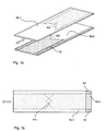
- FIG. 7 shows two mutually displaceable thin glass plates GL1, GL2, for example microscope slide, which are mutually displaceable in the direction of the arrow and which are each partially coated, for example by means of a highly precise lithographic process.
- the coating for GL1 and GL2 is mirror-symmetrical in such a way that a preferably right-angled and sharp-edged angle W1, W2 of the coating remains free and forms the pinhole PH in the case of plates GL1, GL2 lying one above the other. So that the plates do not slide directly onto one another, which can damage the coating, thin Teflon strips TS can be provided on the edges outside the effective area of the pinhole PH on at least one plate, which ensure low-friction sliding and are preferably oriented in the direction of displacement.
- FIG. 8 shows a further embodiment of an adjustable pinhole, consisting of foils FL1-FL4 arranged on lever joints H1-H4.
- the arrangement relates to an arrangement of the film edges according to FIG. 2c.
- 8c shows a complete arrangement in which a pinhole adjustment can be carried out with an arrangement analogous to FIG. 3 by means of a single stepping motor SM.
Landscapes
- Physics & Mathematics (AREA)
- General Physics & Mathematics (AREA)
- Optics & Photonics (AREA)
- Mechanical Light Control Or Optical Switches (AREA)
- Microscoopes, Condenser (AREA)
- Optical Elements Other Than Lenses (AREA)
- Length Measuring Devices By Optical Means (AREA)
- Exposure And Positioning Against Photoresist Photosensitive Materials (AREA)
Abstract
Description
- In DE 20205079 U1 ist ein scherenartiger Verschlußmechanismus für ein Pinhole beschrieben.
Hier ist vor allem die Fertigungsgenauigkeit der Winkelstellen, die sich gegenüberstehen und über die Drehachse gegeneinander bewegt werden sollen, ein ernsthaftes Hindernis für eine reproduzierbare und lichtdichte Schließung und exakte quadratische Form der Pinholeöffnung. - Die Aufgabe besteht darin, ein hochgenaues Pinhole zu entwickeln, das sich lichtdicht verschließen läßt und dessen Öffnung ab der Größe Null eine quadratische Form aufweist.
- Erfindungsgemäß wird dieses Problem gelöst, indem eine Anordnung aus Folienkanten, deren zur Pinholeöffnung zeigenden Kanten vorzugsweise geschliffen sind, gemäß den erfinderischen Ausführungen relativ zueinander bewegt werden. Die Gestaltung der Pinholeöffnung aus Folienkanten bietet den entscheidenden Vorteil, daß die Ecken der Pinholeöffnung vollkommen scharfkantig sind und der Krümmungsradius der Ecken null ist. Hierdurch lassen sich Pinholeöffnungen ab Größe Null reproduzierbar einstellen.
Das Vorfertigen der Folienkanten kann bereits hochgenau erfolgen, beispielsweise durch Schneiden mit Diamantschneiden oder durch Laserschneiden oder durch Ätzen.
Zur vorzugsweisen Bewegung, die sehr exakt und spielfrei ablaufen sollte, sind Festkörpergelenke in Form von elastischen Stegen vorgesehen, an denen eine Verkippung oder Drehung stattfindet.
Die Erfindung gestattet überraschend eine einstellbare und reproduzierbare Verkleinerung der Größe der Pinholeöffung ab Größe Null und dessen lichtdichten Verschluß ohne Kollisiongefahr der Folienkanten untereinander.
Die Erfindung wird nachstehend anhand der schematischen Zeichnungen näher erläutert.
Wenn im folgenden von Folienstücken oder Folienkanten gesprochen wird, geht es im wesentlichen um die bei der Pinholeöffnung und / oder Schließung gegenüberliegenden Kanten, während die übrige Form der Folienstücke je nach Platzbedarf und Ausführung variieren kann. - Das Folienmaterial kann beispielsweise Federstahl, Federbronze oder Aluminium von einer Dicke von beispielsweise 10 µm sein. Die Folienkanten können in einem Verbund, von beispielsweise 100 vorgefertigten Einzelfolien geschliffen, gestanzt und dann wieder getrennt oder auch im Anlieferzustand als Bandmaterial verwendet werden.
- Fig..1a zeigt schematisch eine Abbildung von L- förmig in einem vorzugsweise rechten Winkel angeordneten Folienstücken F1-F4 , wobei F1 und F2 sowie F3 und F4 jeweils an Verbindungspunkten V1, V2 fest miteinander verbunden sind.
Sie sind an ihren den Verbindungspunkten abgewandten Enden jeweils ortsfest (schwarz mit s gekennzeichnet) auf zueinander in Pfeilrichtung verschiebbaren Grundplatten P1 und P2 befestigt, und zwar auf jeder Platte so, daß sich die Pinholeöffnung beim synchronen Bewegen der Platten P1 und P2 in Pfeilrichtung punktförmig öffnet und schließt
Die Verbindung der Folien untereinander und mit den Platten P1 und P2 kann z.B. durch Kleben, Widerstandsschweißen, Diffusionschweißen oder Ultraschallschweißen erfolgen. - Durch die synchrone Verschiebung der Platten P1 und P2 in Pfeilrichtung wird erreicht, daß sich der Öffnungsbereich zwischen den an den Punkten V1, V2 verbundenen Folienkanten verkleinert oder vergrößert, und zwar wird bei Annäherung der Platten P1, P2 das Pinhole PH geöffnet und umgekehrt.
Die Pinholeöffnung schließt sich hierbei vorzugsweise quadratisch bis zu einem Punkt. Bei weiterer Vergrößerung des Abstandes der Platten P1, P2 wird die Pinholeöffnung lichtdicht überdeckt, ohne daß sich die Folienkanten gegenseitig behindern oder beschädigen können. - Durch die Befestigung von jeweils zwei Folienkanten rechtwinklig übereinander ist gewährleistet, daß der durch sie gebildete rechte Winkel keinen Fertigungsproblemen unterliegt.
Ein Verhaken der Folienkanten wird dadurch ausgeschlossen, daß F3 auf F4 verkürzt befestigt ist und somit nicht mit der Folienkante von F2 in Berührung kommt. - In Fig. 1b ist eine weitere Variante der Erfindung dargestellt.
Sie besteht aus kreuzförmig angeordneten kreuzförmigen Folienkanten F5-F8 , die jeweils an den Platten P1 ( F5, F6) bzw. P2 ( F7, F8) befestigt sind, wobei wiederum zwei Platten P1, P2 in Pfeilrichtung zueinander verschiebbar sind, hier jedoch bei Annäherung von P1, P2 sich das Pinhole PH schließt und umgekehrt, weil sich F5-F8 und F6-F7 scherenartig übereinderschieben, da sie nicht miteinander verbunden sind.
Die Öffnung des Pinholes wird hier von den jeweils den Plattenkanten abgewandten Ecken der Foilienanordnungen gebildet. - In Fig. 1c ist eine weitere Variante der Erfindung dargestellt. Jede der Folienkanten F9, F10, F11, F12 weist zwei Gelenke auf, bevorzugt Festkörpergelenke. Der Abstand der Gelenkpunkte G91 zu G92, G101 zu G102, G111 zu G112 und G121 zu G122 sei vorzugsweise gleich und viel größer als die Pinholeöffnung. Die Folienpaare F9, F11 und F10, F12 sind jeweils L-förmig an Ihren Verbindungsstellen V3 und V4 verbunden und kreuzförmig so auf den Platten P1, P2 befestigt, daß beim synchronen Öffnen der Platten P1 und P2 in Pfeilrichtung die Pinholeöffnung punktförmig und vorzugeweise quadratisch schließt und umgekehrt. Das erfolgt dadurch, daß sich bei synchroner Vergrößerung des Abstandes der Platten P1, P2 in Pfeilrichtung die Gelenkpunkte G92 und G102, G112 und G121 senkrecht zur Pfeilrichtung aufeinander zu bewegen und die Pinholeöffnung schließen und umgekehrt. Hierbei öffnen und schließen sich die verbiegbaren Gelenkeinkerbungen an den Folien. Beim Öffnen und Schließen des Pinholes bleibt die Form der Pinholeöffnung annähernd quadratisch.
Bei Vergrößerung des Abstandes der Platten P1, P2 wird die Pinholeöffnung schließlich lichtdicht überdeckt, ohne daß sich die Folienkanten gegenseitig behindern oder zerstören können. - Ein Verhaken der Folienkanten wird dadurch ausgeschlossen, daß F9 auf F11 verkürzt befestigt ist und somit nicht mit der Folienkante F12 in Berührung kommt.
- In Fig. 2 ist eine neue Ausführung dargestellt, wobei jeweils zwei Folienkanten F13, F14, F15, F16 paarweise leicht v-förmig zueinander stehen, d.h. einen kleinen Winkel zueinander einschließen . In Fig. 2a wird das eine Folienpaar zum anderen bezüglich seiner Mittenachse zwischen den Einzelfolien vorzugsweise in Pfeilrichtung senkrecht zueinander synchron verschoben.
Eine senkrechte Verschiebung zueinander, vorzugsweise durch synchrone Bewegung beider Folienpaare über zwei Motoren (nicht dargestellt) ergibt große Stellwege bei der Einstellung der Pinholeöffnung mit hoher Genauigkeit, so daß ggf. auf Wegmeßsysteme verzichtet werden kann.
In Fig. 2b wird der leicht V förmige Öffnungswinkel zwischen den Folienkanten variiert, indem die Folien F17 und F18 um die Achsen A1 und A2 und die Folien F19 und F20 um die Achsen A3 und A4 gegensinnig und vorzugsweise synchron zum Öffnen und Schleißen der Pinholeöffung verdreht werden.
In Fig. 2c befinden sich die Drehachsen A5, A6 und A7, A8 auf den entgegengesetzten Seiten der Folienpaare F21, F22 und F23, F24. Die Drehung der Folien erfolgt vorzugsweise synchron und gleichsinnig. - In Fig. 3 ist eine Anordnung zur Pinholeeinstellung dargestellt, die sich auf Anordnung der Folienkanten gemäß Fig. 1 a bezieht. Die Verschiebung der Platten P1, P2 kann jedoch analog bei Anwendung der Folienkantenanordnung gemäß Fig. 1 b, c erfolgen.
- Hier ist ein lediglich an der Platte P1 drehgesicherter Schrittmotor SM dargestellt, der Spindeln SP1 und SP2 antreibt, die Gewinde mit unterschiedlichen Steigungen aufweisen und die über Muttern M1 und M2, eine Bewegung des mit P1 und P2 verbundenen Führungsteiles F1 senkrecht zur Verstellbewegung von P1, P2 bewirken. Die Teile F und P sind hierbei vorzugeweise aus einem Stück gefertigt und untereinander durch federnde Stege (Parallelfedergelenke) verbunden.
Die Fertigung der Teile kann z.B. durch Laserschneiden, Ätzen, Erodieren oder Stanzen erfolgen.
Der Schrittmotor SM ist zur Platte P1 drehgesichert und frei verschiebbar angeordnet. Er treibt synchron die Spindeln SP1 und SP2 an, die Gewinde mit unterschiedlichen Steigungen aufweisen.(z.B. ergibt sich mit den Gewinden M3x0, 5 und M2,6x0,45 eine Differenzsteigung von 50 µm).
Spindel SP 2 schraubt sich, angetrieben durch Schrittmotor SM, in die am Rahmen F2 befestigte Mutter M2. Der drehgesicherte Schrittmotor SM verschiebt sich daraufhin entlang der Achse A um die Spindelverschiebung in die Pfeilrichtung. - Mutter M1, die am Führungsteil F1 befestigt ist, verschiebt sich aufgrund des Differenzgewindes um einen Betrag, der ca. 10 mal kleiner ist als der des Schrittmotors SM, zur Mutter M2. Das bewirkt eine sehr hohe Feinfühligkeit bei der Verstellung von F1.
Am Führungsteil F1, das durch Federstege (Parallelfedergelenk) mit dem Rahmen verbunden ist, sind die schrägen Federstege ST5, ST6 befestigt, die beim Drehen der Motorwelle sich spreitzen oder schließen und die Platten P1, P2 und damit das Pinhole öffnen oder schließen.
Während der Rahmen F2 über mehrere Stege ST1-ST4 (2 Parallelfedergelenke) mit den Platten P1, P2 zu deren Parallelführung verbunden ist, sind die Platten P1, P2 mit F1 jeweils über federnd gelagerte Stege ST5, ST6 verbunden, die schräg zur Verschieberichtung von P1 und P2 und schräg zu F1, F2 angeordnet sind.
Hierdurch wird erreicht, daß eine Verschiebung von F1 in Pfeilrichtung in eine hierzu senkrechte und antiparallele Verschiebung der Platten P1 und P2 umgewandelt wirdund die resultierende Verstellung der Pinholeöffnung gemäß Fig. 1 oder 2 erfolgt. - In Fig. 3 ist schematisch ein Ausbruch AS dargestellt, in dem sich einWegmeßsystem befinden kann , wie es in Fig.4 beispielhaft dargestellt ist. Es mißt die Relativbewegung der Platten P1, P2 zueinander und damit die Größe der Diagonalen der Pinholeöffnung.
Fest auf Platte P2 ist eine Lichtquelle LED angeordnet, der ebenfalls auf P2 gegenüber ein ortsauflösender Sensor S zugeordnet ist, der die Bewegung eines mit der zu P2 beweglichen Platte P1 verbundenen Maßstabes MR, hier ein transparenter Rastermaßstab, anhand der erfaßten Rasterveränderung erfaßt. Derartige Meßsysteme sind handelsüblich mit einer Genauigkeit ab 0,1 µm erhältlich. Solche handelsüblichen Meßsysteme ermöglichen zusätzlich die Referenzierung des Schrittmotorantriebes.
Anhand der erfaßten Relativbewegung der Platten P1, P2 kann dadurch on - line die Erfassung der tatsächlichen Pinholeöffnung erfaßt werden und auch mit einer optischen Messung bei verschiedenen Pinholeöffnungszuständen korreliert werden. Eine Referenzierung des Schrittmotorantriebes kann in einfacher Weise auch dadurch erfolgen, daß ein zusätzlicher, nicht dargestellter optischer Detektor das im Moment der Öffnung der Pinholeöffnung von einer nicht dargestellten Lichtquelle durch die Pinholeöffnung hindurchtretende Licht erfaßt und in diesem Moment die Referenzierung des Schrittmotrantriebes hochgenau auslöst. - In Fig. 5 ist ein Spindeltrieb , bestehend aus einem Schrittmotor SM1 und Muttern M3, M4 dargestellt, der eine Bewegung einer Platte PLX in X - Richtung gewährleistet. Diese Platte ist beispielsweise über Befestigungspunkte BF1 mit Befestigungspunkten BF auf der Verschiebeeinrichtung gemäß Fig. 4 verbunden, so daß die gesamte Pinholeanordnung gemäß Fig. 4 in X - Richtung - und mit einer weiteren Anordnung , die mit der Anordnung gemäß Fig.5 verbunden sein kann, auch in Y- Richtung verschiebbar ist.. Hierdurch ist eine X- und Y - Verschiebung des Pinholes senkrecht zur optischen Achse, beispielsweise zu Zentrierungszwecken, gewährleistet.
- In Fig. 7 sind zwei zueinander verschiebliche dünne Glasplatten GL1, GL2, beispielsweise Objektträger eines Mikroskopes, dargestellt, die zueinander in Pfeilrichtung verschieblich sind und, beispielsweise über einen hochgenauen lithografischen Prozeß, jeweils teilweise beschichtet sind. Die Beschichtung ist hierbei für GL1 und GL2 spiegelsymmetrisch so ausgeführt, daß jeweils ein vorzugsweise rechtwinkliger und scharfkantiger Winkel W1, W2 der Beschichtung freibleibt und bei übereinanderliegenden Platten GL1, GL2das Pinhole PH bildet. Damit die Platten nicht direkt aufeinander abgleiten, was zu Beschädigungen der Beschichtung führen kann, können an den Rändern außerhalb des Wirkbereiches des Pinholes PH dünne Teflonstreifen TS auf mindestens einer Platte vorgesehen sein, die ein reibungsarmes Abgleiten gewährleisten und vorzugsweise in Richtung der Verschiebung orientiert sind. Teflon gleitet nur auf einer glatten Glasoberfläche fast ideal abreibfrei. Deshalb soll sich im Bereich der Teflonschichten keine Chromschicht auf den Glasplatten befinden.
Zur Vermeidung von Reflexionsverlusten an den einander zugewandten Flächen der Glasplatten GL1 und GL2 kann zwischen den Glasplatten eine Immersionsflüssigkeit eingebracht werden. - In Fig. 8 ist eine weitere Ausführung eines einstellbaren Pinholes dargestellt, bestehend aus an Hebelgelenken H1 -H4 angeordneten Folien FL1-FL4. Die Anordnung bezieht sich auf eine Anordnung der Folienkanten nach Fig. 2c.
- Die Hebelgelenke H1-H4, die vorzugsweise gleichlang sind, sind miteinander gelenkig verbunden und bilden einen verstellbaren Rhombus. Die Verstellung erfolgt an den Punkten A1, A2 über ein Zusammenführen oder Auseinanderziehen von mit A1 und A2 verbundenen Hebelarmen HA1, HA2, die an Drehpunkten A3, A4 gelagert sind.
Werden beispielsweise HA1 und HA2 zueinander bewegt (Pfeilrichtung in Fig. 8b), kommte es zu folgenden Drehbewegungen: - FL1 entgegen dem Uhrzeigersinn
- FL2 im Uhrzeigersinn
- FL3 entgegen dem Uhrzeigersinn
- FL4 im Uhrzeigersinn, so daß sich jeweils zwei Folien FL zueinander bewegen und damit das Pinhole geschlossen wird.
- Beim Auseinanderziehen von HA1 und HA2 geschieht das Gegenteil.
In Fig. 8c ist eine komplette Anordnung dargestellt, in der mit einer Anordnung analog zu Fig. 3 mittels eines einzigen Schrittmotors SM eine Pinholeverstellung erfolgen kann.
Claims (16)
- Einstellbares Pinhole für den Beleuchtungs- und/ oder Detektionsstrahlengang eines Laser-Scanning-Mikroskopes,
wobei die Pinholeöffnung durch zueinander verstellbare Folienkanten begrenzt wird. - Einstellbares Pinhole nach Anspruch 1,
wobei mindestens zwei Folien mit jeweils mindestens einer geraden Kante so zueinander angeordnet werden und / oder miteinander verbunden sind, daß ihre Kanten eine L- Form beschreiben und die L-förmigen Verbindungsstücke so aufeinander angeordnet werden, daß sie einen rhombischen oder quadratischen Lichtdurchtritt umgrenzen und sie zueinander zur Pinholeverstellung bewegt werden. - Einstellbares Pinhole nach Anspruch 2, wobei die Bewegungsrichtung in Richtung der Winkelhalbierenden des durch die L-Form aufgespannten Winkels oder eines anderen innerhalb des aufgespannten Winkels liegenden Winkels erfolgt.
- Einstellbares Pinhole für den Beleuchtungs- und/ oder Detektionsstrahlengang eines Laser-Scanning-Mikroskopes,
wobei mindestens zwei Folien mit jeweils mindestens einer geraden Kante so verbunden werden, daß ihre Kanten einen kleinen Winkel, vorzugsweise um 4 Grad zueinander, aufweisen und zwei derartige Folienpaare zueinander senkrecht oder in einem Winkel zur Pinholeverstellung verschoben werden - Einstellbares Pinhole für den Beleuchtungs- und / oder Detektionsstrahlengang eines Laser-Scanning-Mikroskopes,
wobei mindestens zwei Folien mit jeweils mindestens einer geraden Kante so stehen, daß ihre Kanten einen kleinen Winkel , vorzugsweise um 4 Grad zueinander aufweisen und zwei derartige Folienpaare jeweils zueinander gegensinnig oder gleichsinnig verdreht werden. - Einstellbares Pinhole, wobei zwei teilweise beschichtete transparente Träger gegeneinander verschoben werden und die Beschichtungen Winkelsegmente aufweisen, die gemeinsam das Pinhole begrenzen.
- Einstellbares Pinhole nach Anspruch 6, wobei zwischen den Trägern Teflonstreifen und/ oder eine Immersionsflüssigkeit vorgesehen ist.
- Einstellbares Pinhole mit einer zueinander verstellbaren Hebelanordnung,
wobei zwischen ersten Hebeln eine rhombische Anordnung aus mindestens vier zueinander verstellbaren zweiten Hebeln angeordnet ist, die jeweils ein Folienstück mit einer schräg zum Hebelverlauf angeordneten Folienkante tragen - Einstellbares Pinhole nach einem der vorangehenden Ansprüche, wobei die Folien Festkörpergelenke aufweisen
- Einstellbares Pinhole nach einem der vorangehenden Ansprüche, wobei zur Verstellung der Folienkanten motorisch antreibbare Festkörpergelenke vorgesehen sind.
- Einstellbares Pinhole nach einem der vorangehenden Ansprüche, wobei eine Verstellung mittels eines Schrittmotors erfolgt, der über mindestens zwei gleichlaufende Spindeln, vorzugsweise mit unterschiedlicher Steigung verschiebbare Platten antreibt, an denen die Folien befestigt sind.
- Einstellbares Pinhole nach einem der vorangehenden Ansprüche, wobei über ein Wegmeßsystem und / oder einen optischen Detektor zur Erfassung der durch das Pinhole hindurchtretenden Lichtmenge eine Referenzierung des Schrittmotorantriebes erfolgt.
- Einstellbares Pinhole nach einem der vorangehenden Ansprüche, wobei das Pinhole so schließbar ist, daß sich die Folien überlappen.
- Einstellbares Pinhole nach einem der vorangehenden Ansprüche, wobei mindestens ein Folienpaar zum Kollisionsschutz eine Versetzung aufweist.
- Verfahren zur Herstellung eines einstellbaren Pinholes, insbesondere nach einem der vorangehenden Ansprüche, dadurch gekennzeichnet, daß das Pinhole begrenzende Folienkanten erzeugt werden, indem Folienmaterial einzeln oder im Verbund an mindestens einer Seite gerade abgeschnitten wird.
- Verfahren zur Herstellung eines einstellbaren Pinholes, vorzugsweise nach Anspruch 15, wobei die Folienkanten zur Erhöhung der Genauigkeit, vorzugsweise durch Schleifen, nach dem Abschneiden nachbehandelt werden.
Priority Applications (1)
| Application Number | Priority Date | Filing Date | Title |
|---|---|---|---|
| EP07022484A EP1882960A3 (de) | 2002-09-24 | 2003-09-11 | Einstellbares Pinhole mit zwei verschiebbare, teilweise beschichteten, transparenten Trägern |
Applications Claiming Priority (2)
| Application Number | Priority Date | Filing Date | Title |
|---|---|---|---|
| DE10244850A DE10244850A1 (de) | 2002-09-24 | 2002-09-24 | Einstellbares Pinhole |
| DE10244850 | 2002-09-24 |
Related Child Applications (1)
| Application Number | Title | Priority Date | Filing Date |
|---|---|---|---|
| EP07022484A Division EP1882960A3 (de) | 2002-09-24 | 2003-09-11 | Einstellbares Pinhole mit zwei verschiebbare, teilweise beschichteten, transparenten Trägern |
Publications (3)
| Publication Number | Publication Date |
|---|---|
| EP1403674A2 true EP1403674A2 (de) | 2004-03-31 |
| EP1403674A3 EP1403674A3 (de) | 2004-05-26 |
| EP1403674B1 EP1403674B1 (de) | 2007-11-21 |
Family
ID=31969610
Family Applications (2)
| Application Number | Title | Priority Date | Filing Date |
|---|---|---|---|
| EP07022484A Withdrawn EP1882960A3 (de) | 2002-09-24 | 2003-09-11 | Einstellbares Pinhole mit zwei verschiebbare, teilweise beschichteten, transparenten Trägern |
| EP03020426A Expired - Lifetime EP1403674B1 (de) | 2002-09-24 | 2003-09-11 | Einstellbares Pinhole |
Family Applications Before (1)
| Application Number | Title | Priority Date | Filing Date |
|---|---|---|---|
| EP07022484A Withdrawn EP1882960A3 (de) | 2002-09-24 | 2003-09-11 | Einstellbares Pinhole mit zwei verschiebbare, teilweise beschichteten, transparenten Trägern |
Country Status (4)
| Country | Link |
|---|---|
| US (2) | US7324253B2 (de) |
| EP (2) | EP1882960A3 (de) |
| JP (1) | JP2004118190A (de) |
| DE (2) | DE10244850A1 (de) |
Cited By (2)
| Publication number | Priority date | Publication date | Assignee | Title |
|---|---|---|---|---|
| EP1897095A2 (de) * | 2005-06-20 | 2008-03-12 | Bundesanstalt Für Materialforschung Und -Prufung (Bam) | Blende für eine bildgebende einrichtung |
| CN104981726A (zh) * | 2013-02-05 | 2015-10-14 | 皮克斯特隆尼斯有限公司 | 并入有多级快门的显示设备 |
Families Citing this family (7)
| Publication number | Priority date | Publication date | Assignee | Title |
|---|---|---|---|---|
| JP4354207B2 (ja) | 2003-04-15 | 2009-10-28 | オリンパス株式会社 | 顕微鏡装置 |
| JP5228257B2 (ja) * | 2006-12-26 | 2013-07-03 | 日本精工株式会社 | 可視下遠心装置及び観察装置 |
| KR20080078165A (ko) * | 2007-02-22 | 2008-08-27 | 삼성전자주식회사 | 레이저 리페어 시스템 |
| DE102010036790A1 (de) * | 2010-08-02 | 2012-02-02 | Leica Microsystems Cms Gmbh | Einrichtung zur lückenlosen Einstellung von Spektrometer-Spaltbreiten |
| KR20130130779A (ko) | 2010-12-20 | 2013-12-02 | 픽스트로닉스 인코포레이티드 | 감소된 음향 방출을 갖는 mems 광 변조기 어레이들을 위한 시스템들 및 방법들 |
| CN114850216B (zh) * | 2022-07-04 | 2022-10-04 | 太原理工大学 | 一种电控微爆炸成型制备双金属复合板的方法 |
| DE102023001734A1 (de) | 2023-04-28 | 2024-10-31 | PicoQuant Innovations GmbH | Lochblendeneinrichtung mit einer einstellbaren Apertur |
Family Cites Families (16)
| Publication number | Priority date | Publication date | Assignee | Title |
|---|---|---|---|---|
| US2964998A (en) * | 1958-10-03 | 1960-12-20 | Fred J Middlestadt | Precision light aperture arrangement |
| FR2022123A1 (de) * | 1968-08-14 | 1970-07-31 | Wollnik Hermann | |
| GB1327394A (en) * | 1969-10-23 | 1973-08-22 | Atomic Energy Authority Uk | Adjustable slits |
| US4017162A (en) * | 1973-08-13 | 1977-04-12 | Varian Techtron Pty. Ltd. | Adjustable slit mechanism |
| EP0276337B1 (de) * | 1987-01-24 | 1989-11-29 | Dr.-Ing. Rudolf Hell GmbH | Blendenanordnung zur optoelektronischen Abtastung von Vorlagen |
| NL8700496A (nl) * | 1987-02-27 | 1988-09-16 | Stichting Tech Wetenschapp | Continu variabel microdiafragma. |
| US4904055A (en) * | 1988-10-03 | 1990-02-27 | Eastman Kodak Company | Variable aperture formed by linearly movable elements |
| JPH0519206A (ja) * | 1990-10-26 | 1993-01-29 | Toyo Ink Mfg Co Ltd | 光ビームのサイズ制御方法 |
| US5105582A (en) * | 1991-04-17 | 1992-04-21 | Bell Peter M | Cup cutter sharpener |
| JPH04358110A (ja) * | 1991-06-05 | 1992-12-11 | Olympus Optical Co Ltd | 可変ピンホール |
| DE4212077A1 (de) * | 1992-04-10 | 1993-10-14 | Fraunhofer Ges Forschung | Piezoelektrisch verstellbares Ventil und Verfahren zu ihrer Herstellung |
| JPH09159935A (ja) * | 1995-12-12 | 1997-06-20 | Olympus Optical Co Ltd | 可変ピンホール機構 |
| US5907733A (en) * | 1997-11-21 | 1999-05-25 | Nisca Corporation | Exposing aperture device for a camera |
| DE10111465A1 (de) * | 2001-03-09 | 2002-09-12 | Bodenseewerk Geraetetech | Blendenanordnung für ein mikrooptisches System |
| DE10132119A1 (de) * | 2001-07-03 | 2003-01-16 | Claus Bild Und Datentechnik Gm | Motorische Blende für optische Baugruppen |
| DE20205079U1 (de) * | 2002-03-30 | 2002-06-13 | Leica Microsystems | Variable Lochblende und konfokales Scanmikroskop |
-
2002
- 2002-09-24 DE DE10244850A patent/DE10244850A1/de not_active Withdrawn
-
2003
- 2003-09-11 EP EP07022484A patent/EP1882960A3/de not_active Withdrawn
- 2003-09-11 EP EP03020426A patent/EP1403674B1/de not_active Expired - Lifetime
- 2003-09-11 DE DE50308633T patent/DE50308633D1/de not_active Expired - Lifetime
- 2003-09-18 JP JP2003326525A patent/JP2004118190A/ja active Pending
- 2003-09-24 US US10/669,394 patent/US7324253B2/en not_active Expired - Fee Related
-
2007
- 2007-10-29 US US11/926,435 patent/US7400433B2/en not_active Expired - Fee Related
Cited By (2)
| Publication number | Priority date | Publication date | Assignee | Title |
|---|---|---|---|---|
| EP1897095A2 (de) * | 2005-06-20 | 2008-03-12 | Bundesanstalt Für Materialforschung Und -Prufung (Bam) | Blende für eine bildgebende einrichtung |
| CN104981726A (zh) * | 2013-02-05 | 2015-10-14 | 皮克斯特隆尼斯有限公司 | 并入有多级快门的显示设备 |
Also Published As
| Publication number | Publication date |
|---|---|
| JP2004118190A (ja) | 2004-04-15 |
| DE50308633D1 (de) | 2008-01-03 |
| EP1882960A2 (de) | 2008-01-30 |
| DE10244850A1 (de) | 2004-04-01 |
| EP1403674A3 (de) | 2004-05-26 |
| US7400433B2 (en) | 2008-07-15 |
| US20040134889A1 (en) | 2004-07-15 |
| EP1882960A3 (de) | 2008-06-25 |
| US20080049294A1 (en) | 2008-02-28 |
| EP1403674B1 (de) | 2007-11-21 |
| US7324253B2 (en) | 2008-01-29 |
Similar Documents
| Publication | Publication Date | Title |
|---|---|---|
| DE2361155C2 (de) | Vorrichtung zum Positionieren eines ersten Gegenstandes in bezug auf einen zweiten Gegenstand | |
| DE2854856C2 (de) | ||
| DE69200553T2 (de) | Beweglicher Objekttisch. | |
| EP0271646B1 (de) | Vorrichtung zur berührungsfreien Messung eines Abstandes von einer Oberfläche, insbesondere zur Abtastung einer Kontur einer Oberfläche eines Werkstückes länges eines Messweges | |
| EP1133377A1 (de) | Vorrichtung und verfahren zum abtasten einer objektfläche mit einem laserstrahl | |
| DE2803375A1 (de) | Vorrichtung zum messen von biegewinkeln bei blechabkantpressen | |
| DE69016576T2 (de) | Zweistrahl-Interferometer für ein Fourier-Spektrometer sowie Antriebsvorrichtung für einen beweglichen Planspiegel dafür. | |
| EP1403674A2 (de) | Einstellbares Pinhole | |
| DE3390532C2 (de) | Optisches System zur mehrfachen Reflexion | |
| DE2159134B2 (de) | Einrichtung zur interferometrischen messung der verschiebung eines schlittens | |
| DE69902341T2 (de) | Optische Anordnung, insbesondere Spiegel oder Verschlussvorrichtung, mit elektrostatischem Antrieb und variablem Betriebszustand | |
| DE4229507C2 (de) | Mikromechanischer 3-D-Aktor | |
| DE19744938A1 (de) | Optische Positionsmeßeinrichtung | |
| DE10125031A1 (de) | Tischpositioniervorrichtung | |
| DE3102684C2 (de) | ||
| DE2164607C3 (de) | Vorrichtung zur Erzeugung eines parallel zu sich selbst verschobenen Fahrstrahles | |
| DE69219005T2 (de) | Optischer Kopfantrieb | |
| WO2017178223A1 (de) | Positionsmessanordnung und verfahren zum betrieb einer positionsmessanordnung | |
| DE20205079U1 (de) | Variable Lochblende und konfokales Scanmikroskop | |
| DE102016125255A1 (de) | Wellenfrontmanipulator und optisches Gerät | |
| WO2004104647A1 (de) | Einstellbares pinhole | |
| DE2432671A1 (de) | Vorrichtung zum messen und bearbeiten von werkstuecken | |
| DE3820783C2 (de) | ||
| DE10215178B4 (de) | Vorrichtung und Verfahren zur quantitativen Analyse der Verteilung der kristallographischen Orientierung von Kristalliten in einem Polykristall mit Hilfe von Röntgenstrahlen | |
| DD249989B1 (de) | Feinpositionierende justiervorrichtung |
Legal Events
| Date | Code | Title | Description |
|---|---|---|---|
| PUAI | Public reference made under article 153(3) epc to a published international application that has entered the european phase |
Free format text: ORIGINAL CODE: 0009012 |
|
| 17P | Request for examination filed |
Effective date: 20030911 |
|
| AK | Designated contracting states |
Kind code of ref document: A2 Designated state(s): AT BE BG CH CY CZ DE DK EE ES FI FR GB GR HU IE IT LI LU MC NL PT RO SE SI SK TR |
|
| AX | Request for extension of the european patent |
Extension state: AL LT LV MK |
|
| PUAL | Search report despatched |
Free format text: ORIGINAL CODE: 0009013 |
|
| AK | Designated contracting states |
Kind code of ref document: A3 Designated state(s): AT BE BG CH CY CZ DE DK EE ES FI FR GB GR HU IE IT LI LU MC NL PT RO SE SI SK TR |
|
| AX | Request for extension of the european patent |
Extension state: AL LT LV MK |
|
| AKX | Designation fees paid |
Designated state(s): AT BE BG CH CY CZ DE DK EE ES FI FR GB GR HU IE IT LI LU MC NL PT RO SE SI SK TR |
|
| 17Q | First examination report despatched |
Effective date: 20050113 |
|
| GRAP | Despatch of communication of intention to grant a patent |
Free format text: ORIGINAL CODE: EPIDOSNIGR1 |
|
| RIN1 | Information on inventor provided before grant (corrected) |
Inventor name: BARTZKE, KARLHEINZ Inventor name: WOLLESCHENSKY, RALF Inventor name: KLOPFLEISCH, KARL-HEINZ Inventor name: HOFMANN, JENS |
|
| GRAS | Grant fee paid |
Free format text: ORIGINAL CODE: EPIDOSNIGR3 |
|
| GRAA | (expected) grant |
Free format text: ORIGINAL CODE: 0009210 |
|
| AK | Designated contracting states |
Kind code of ref document: B1 Designated state(s): AT BE BG CH CY CZ DE DK EE ES FI FR GB GR HU IE IT LI LU MC NL PT RO SE SI SK TR |
|
| REG | Reference to a national code |
Ref country code: GB Ref legal event code: FG4D Free format text: NOT ENGLISH |
|
| REG | Reference to a national code |
Ref country code: IE Ref legal event code: FG4D Free format text: LANGUAGE OF EP DOCUMENT: GERMAN |
|
| REG | Reference to a national code |
Ref country code: CH Ref legal event code: EP |
|
| REF | Corresponds to: |
Ref document number: 50308633 Country of ref document: DE Date of ref document: 20080103 Kind code of ref document: P |
|
| GBT | Gb: translation of ep patent filed (gb section 77(6)(a)/1977) |
Effective date: 20080205 |
|
| ET | Fr: translation filed | ||
| PG25 | Lapsed in a contracting state [announced via postgrant information from national office to epo] |
Ref country code: ES Free format text: LAPSE BECAUSE OF FAILURE TO SUBMIT A TRANSLATION OF THE DESCRIPTION OR TO PAY THE FEE WITHIN THE PRESCRIBED TIME-LIMIT Effective date: 20080304 Ref country code: SE Free format text: LAPSE BECAUSE OF FAILURE TO SUBMIT A TRANSLATION OF THE DESCRIPTION OR TO PAY THE FEE WITHIN THE PRESCRIBED TIME-LIMIT Effective date: 20080221 Ref country code: NL Free format text: LAPSE BECAUSE OF FAILURE TO SUBMIT A TRANSLATION OF THE DESCRIPTION OR TO PAY THE FEE WITHIN THE PRESCRIBED TIME-LIMIT Effective date: 20071121 |
|
| NLV1 | Nl: lapsed or annulled due to failure to fulfill the requirements of art. 29p and 29m of the patents act | ||
| PG25 | Lapsed in a contracting state [announced via postgrant information from national office to epo] |
Ref country code: FI Free format text: LAPSE BECAUSE OF FAILURE TO SUBMIT A TRANSLATION OF THE DESCRIPTION OR TO PAY THE FEE WITHIN THE PRESCRIBED TIME-LIMIT Effective date: 20071121 Ref country code: BG Free format text: LAPSE BECAUSE OF FAILURE TO SUBMIT A TRANSLATION OF THE DESCRIPTION OR TO PAY THE FEE WITHIN THE PRESCRIBED TIME-LIMIT Effective date: 20080221 Ref country code: SI Free format text: LAPSE BECAUSE OF FAILURE TO SUBMIT A TRANSLATION OF THE DESCRIPTION OR TO PAY THE FEE WITHIN THE PRESCRIBED TIME-LIMIT Effective date: 20071121 |
|
| PG25 | Lapsed in a contracting state [announced via postgrant information from national office to epo] |
Ref country code: CZ Free format text: LAPSE BECAUSE OF FAILURE TO SUBMIT A TRANSLATION OF THE DESCRIPTION OR TO PAY THE FEE WITHIN THE PRESCRIBED TIME-LIMIT Effective date: 20071121 Ref country code: DK Free format text: LAPSE BECAUSE OF FAILURE TO SUBMIT A TRANSLATION OF THE DESCRIPTION OR TO PAY THE FEE WITHIN THE PRESCRIBED TIME-LIMIT Effective date: 20071121 |
|
| PG25 | Lapsed in a contracting state [announced via postgrant information from national office to epo] |
Ref country code: SK Free format text: LAPSE BECAUSE OF FAILURE TO SUBMIT A TRANSLATION OF THE DESCRIPTION OR TO PAY THE FEE WITHIN THE PRESCRIBED TIME-LIMIT Effective date: 20071121 Ref country code: RO Free format text: LAPSE BECAUSE OF FAILURE TO SUBMIT A TRANSLATION OF THE DESCRIPTION OR TO PAY THE FEE WITHIN THE PRESCRIBED TIME-LIMIT Effective date: 20071121 |
|
| PLBE | No opposition filed within time limit |
Free format text: ORIGINAL CODE: 0009261 |
|
| STAA | Information on the status of an ep patent application or granted ep patent |
Free format text: STATUS: NO OPPOSITION FILED WITHIN TIME LIMIT |
|
| PG25 | Lapsed in a contracting state [announced via postgrant information from national office to epo] |
Ref country code: PT Free format text: LAPSE BECAUSE OF FAILURE TO SUBMIT A TRANSLATION OF THE DESCRIPTION OR TO PAY THE FEE WITHIN THE PRESCRIBED TIME-LIMIT Effective date: 20080421 |
|
| REG | Reference to a national code |
Ref country code: IE Ref legal event code: FD4D |
|
| 26N | No opposition filed |
Effective date: 20080822 |
|
| PG25 | Lapsed in a contracting state [announced via postgrant information from national office to epo] |
Ref country code: IE Free format text: LAPSE BECAUSE OF FAILURE TO SUBMIT A TRANSLATION OF THE DESCRIPTION OR TO PAY THE FEE WITHIN THE PRESCRIBED TIME-LIMIT Effective date: 20071121 |
|
| PG25 | Lapsed in a contracting state [announced via postgrant information from national office to epo] |
Ref country code: GR Free format text: LAPSE BECAUSE OF FAILURE TO SUBMIT A TRANSLATION OF THE DESCRIPTION OR TO PAY THE FEE WITHIN THE PRESCRIBED TIME-LIMIT Effective date: 20080222 |
|
| BERE | Be: lapsed |
Owner name: CARL ZEISS JENA G.M.B.H. Effective date: 20080930 |
|
| PG25 | Lapsed in a contracting state [announced via postgrant information from national office to epo] |
Ref country code: MC Free format text: LAPSE BECAUSE OF NON-PAYMENT OF DUE FEES Effective date: 20080930 Ref country code: EE Free format text: LAPSE BECAUSE OF FAILURE TO SUBMIT A TRANSLATION OF THE DESCRIPTION OR TO PAY THE FEE WITHIN THE PRESCRIBED TIME-LIMIT Effective date: 20071121 |
|
| REG | Reference to a national code |
Ref country code: CH Ref legal event code: PL |
|
| PG25 | Lapsed in a contracting state [announced via postgrant information from national office to epo] |
Ref country code: BE Free format text: LAPSE BECAUSE OF NON-PAYMENT OF DUE FEES Effective date: 20080930 Ref country code: CY Free format text: LAPSE BECAUSE OF FAILURE TO SUBMIT A TRANSLATION OF THE DESCRIPTION OR TO PAY THE FEE WITHIN THE PRESCRIBED TIME-LIMIT Effective date: 20071121 |
|
| PG25 | Lapsed in a contracting state [announced via postgrant information from national office to epo] |
Ref country code: LI Free format text: LAPSE BECAUSE OF NON-PAYMENT OF DUE FEES Effective date: 20080930 Ref country code: AT Free format text: LAPSE BECAUSE OF NON-PAYMENT OF DUE FEES Effective date: 20080911 Ref country code: CH Free format text: LAPSE BECAUSE OF NON-PAYMENT OF DUE FEES Effective date: 20080930 |
|
| PG25 | Lapsed in a contracting state [announced via postgrant information from national office to epo] |
Ref country code: LU Free format text: LAPSE BECAUSE OF NON-PAYMENT OF DUE FEES Effective date: 20080911 Ref country code: HU Free format text: LAPSE BECAUSE OF FAILURE TO SUBMIT A TRANSLATION OF THE DESCRIPTION OR TO PAY THE FEE WITHIN THE PRESCRIBED TIME-LIMIT Effective date: 20080522 |
|
| PG25 | Lapsed in a contracting state [announced via postgrant information from national office to epo] |
Ref country code: TR Free format text: LAPSE BECAUSE OF FAILURE TO SUBMIT A TRANSLATION OF THE DESCRIPTION OR TO PAY THE FEE WITHIN THE PRESCRIBED TIME-LIMIT Effective date: 20071121 |
|
| PG25 | Lapsed in a contracting state [announced via postgrant information from national office to epo] |
Ref country code: IT Free format text: LAPSE BECAUSE OF NON-PAYMENT OF DUE FEES Effective date: 20080930 |
|
| REG | Reference to a national code |
Ref country code: DE Ref legal event code: R082 Ref document number: 50308633 Country of ref document: DE Representative=s name: GEYER, FEHNERS & PARTNER (G.B.R.), DE |
|
| REG | Reference to a national code |
Ref country code: DE Ref legal event code: R081 Ref document number: 50308633 Country of ref document: DE Owner name: CARL ZEISS MICROSCOPY GMBH, DE Free format text: FORMER OWNER: CARL ZEISS JENA GMBH, 07745 JENA, DE Effective date: 20130724 Ref country code: DE Ref legal event code: R082 Ref document number: 50308633 Country of ref document: DE Representative=s name: GEYER, FEHNERS & PARTNER (G.B.R.), DE Effective date: 20130724 |
|
| PGFP | Annual fee paid to national office [announced via postgrant information from national office to epo] |
Ref country code: DE Payment date: 20130919 Year of fee payment: 11 |
|
| PGFP | Annual fee paid to national office [announced via postgrant information from national office to epo] |
Ref country code: GB Payment date: 20130919 Year of fee payment: 11 Ref country code: FR Payment date: 20130919 Year of fee payment: 11 |
|
| REG | Reference to a national code |
Ref country code: DE Ref legal event code: R119 Ref document number: 50308633 Country of ref document: DE |
|
| GBPC | Gb: european patent ceased through non-payment of renewal fee |
Effective date: 20140911 |
|
| REG | Reference to a national code |
Ref country code: DE Ref legal event code: R119 Ref document number: 50308633 Country of ref document: DE Effective date: 20150401 |
|
| REG | Reference to a national code |
Ref country code: FR Ref legal event code: ST Effective date: 20150529 |
|
| PG25 | Lapsed in a contracting state [announced via postgrant information from national office to epo] |
Ref country code: GB Free format text: LAPSE BECAUSE OF NON-PAYMENT OF DUE FEES Effective date: 20140911 Ref country code: DE Free format text: LAPSE BECAUSE OF NON-PAYMENT OF DUE FEES Effective date: 20150401 |
|
| PG25 | Lapsed in a contracting state [announced via postgrant information from national office to epo] |
Ref country code: FR Free format text: LAPSE BECAUSE OF NON-PAYMENT OF DUE FEES Effective date: 20140930 |