EP1403674A2 - Trou d'epingle reglable - Google Patents
Trou d'epingle reglable Download PDFInfo
- Publication number
- EP1403674A2 EP1403674A2 EP03020426A EP03020426A EP1403674A2 EP 1403674 A2 EP1403674 A2 EP 1403674A2 EP 03020426 A EP03020426 A EP 03020426A EP 03020426 A EP03020426 A EP 03020426A EP 1403674 A2 EP1403674 A2 EP 1403674A2
- Authority
- EP
- European Patent Office
- Prior art keywords
- pinhole
- adjustable
- another
- edges
- foils
- Prior art date
- Legal status (The legal status is an assumption and is not a legal conclusion. Google has not performed a legal analysis and makes no representation as to the accuracy of the status listed.)
- Granted
Links
Images


Classifications
-
- G—PHYSICS
- G02—OPTICS
- G02B—OPTICAL ELEMENTS, SYSTEMS OR APPARATUS
- G02B5/00—Optical elements other than lenses
- G02B5/005—Diaphragms
Definitions
- the task is to develop a high-precision pinhole that can be closed light-tight and whose opening has a square shape from size zero.
- this problem is solved in that an arrangement of film edges, the edges of which point towards the pinhole opening are preferably ground, are moved relative to one another in accordance with the inventive embodiments.
- the design of the pinhole opening from film edges offers the decisive advantage that the corners of the pinhole opening are completely sharp and the radius of curvature of the corners is zero. This allows pinhole openings to be reproducibly set from size zero.
- the film edges can already be prefabricated with high precision, for example by cutting with diamond cutting or by laser cutting or by etching. For preferred movement, which should run very precisely and without play, solid-state joints in the form of elastic webs are provided, on which tilting or rotation takes place.
- the invention surprisingly allows an adjustable and reproducible reduction in the size of the pinhole opening from size zero and its light-tight closure without risk of collision between the film edges.
- the invention is explained below with reference to the schematic drawings.
- the foil material can be, for example, spring steel, spring bronze or aluminum with a thickness of, for example, 10 ⁇ m.
- the film edges can be ground in a composite, for example 100 prefabricated individual films, punched and then separated again or used as a strip material in the delivery state.
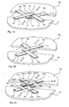
- connection points V1, V2 show schematically an image of L-shaped film pieces F1-F4 arranged at a preferably right angle, F1 and F2 as well as F3 and F4 being firmly connected to one another at connection points V1, V2. They are fixed at their ends facing away from the connection points (black marked s) on base plates P1 and P2 which can be displaced in the direction of the arrow, on each plate such that the pinhole opening opens punctually when the plates P1 and P2 are moved synchronously in the direction of the arrow and closes
- the foils can be connected to one another and to the plates P1 and P2, for example by gluing, resistance welding, diffusion welding or ultrasonic welding.
- the opening area between the film edges connected at points V1, V2 is reduced or enlarged, namely when the plates P1, P2 approach, the pinhole PH is opened and vice versa.
- the pinhole opening closes preferably square to a point. If the distance between the plates P1, P2 is increased further, the pinhole opening is covered in a light-tight manner without the film edges being able to hinder or damage one another.
- FIG. 1b shows a further variant of the invention. It consists of cross-shaped, cross-shaped foil edges F5-F8, each of which is attached to the plates P1 (F5, F6) or P2 (F7, F8), two plates P1, P2 again being displaceable in the direction of the arrow, but here when approaching from P1, P2 the pinhole PH closes and vice versa, because F5-F8 and F6-F7 slide over each other like scissors because they are not connected to each other.
- the opening of the pinhole is formed here by the corners of the foil arrangements facing away from the plate edges.
- FIG. 1c A further variant of the invention is shown in FIG. 1c.
- Each of the film edges F9, F10, F11, F12 has two joints, preferably solid joints.
- the distance between the articulation points G91 to G92, G101 to G102, G111 to G112 and G121 to G122 is preferably the same and much larger than the pinhole opening.
- the pairs of foils F9, F11 and F10, F12 are each L-shaped at their connection points V3 and V4 and attached in a cross shape on the plates P1, P2 so that when the plates P1 and P2 are opened synchronously in the direction of the arrow, the pinhole opening closes punctually and preferably square and vice versa.
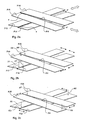
- Fig. 2 a new embodiment is shown, wherein two foil edges F13, F14, F15, F16 in pairs are slightly V-shaped to each other, ie enclose a small angle to each other.
- the one pair of foils to the other with respect to its center axis between the individual foils, preferably displaced synchronously to one another in the direction of the arrow.
- a vertical displacement to one another preferably by synchronous movement of the two pairs of foils via two motors (not shown), results in large travel ranges when setting the pinhole opening with high accuracy, so that it is possible to dispense with position measuring systems.
- Fig. 2 a new embodiment is shown, wherein two foil edges F13, F14, F15, F16 in pairs are slightly V-shaped to each other, ie enclose a small angle to each other.
- the one pair of foils to the other with respect to its center axis between the individual foils, preferably displaced synchronously to one another in the direction of the arrow.
- the slightly V-shaped opening angle between the film edges is varied in that the films F17 and F18 about the axes A1 and A2 and the films F19 and F20 about the axes A3 and A4 are rotated in opposite directions and preferably synchronously with the opening and closing of the pinhole opening become.
- the axes of rotation A5, A6 and A7, A8 are on the opposite sides of the pairs of foils F21, F22 and F23, F24.
- the films are preferably rotated synchronously and in the same direction.
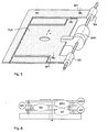
- FIG. 3 shows an arrangement for pinhole adjustment, which relates to the arrangement of the film edges according to FIG. 1a.
- the displacement of the plates P1, P2 can, however, take place analogously when using the film edge arrangement according to FIG.
- a stepper motor SM which is only secured against rotation on the plate P1 is shown, which drives spindles SP1 and SP2, which have threads with different pitches and which, via nuts M1 and M2, a movement of the guide part F1 connected to P1 and P2 perpendicular to the adjustment movement of P1, P2 effect.
- the parts F and P are preferably made from one piece and connected to each other by resilient webs (parallel spring joints). The parts can be manufactured, for example, by laser cutting, etching, eroding or punching.
- the stepper motor SM is secured against rotation with respect to the plate P1 and is freely displaceable.
- spindle SP 2 screws, driven by stepper motor SM, into nut M2 attached to frame F2.
- the non-rotating stepper motor SM then moves along the axis A by the spindle displacement in the direction of the arrow.
- While the frame F2 is connected via several webs ST1-ST4 (2 parallel spring joints) to the plates P1, P2 for their parallel guidance, the plates P1, P2 are connected to F1 via spring-mounted webs ST5, ST6, which are inclined to the direction of displacement of P1 and P2 and are arranged obliquely to F1, F2. It is hereby achieved that a shift from F1 in the direction of the arrow is converted into a perpendicular and antiparallel shift of the plates P1 and P2 and the resulting adjustment of the pinhole opening according to FIG. 1 or 2 takes place.
- FIG. 3 schematically shows an outbreak AS in which a path measuring system can be located, as is shown by way of example in FIG. It measures the relative movement of the plates P1, P2 to one another and thus the size of the diagonals of the pinhole opening.
- Fixed on plate P2 is a light source LED, which is also assigned to P2 a position-resolving sensor S which detects the movement of a scale MR connected to the plate P1 which is movable to P2, here a transparent grid scale, on the basis of the detected grid change.
- Such measuring systems are commercially available with an accuracy of 0.1 ⁇ m.
- Such commercially available measuring systems also allow referencing of the stepper motor drive.
- the detection of the actual pinhole opening can be detected online and also correlated with an optical measurement at different pinhole opening states.
- the stepping motor drive can also be referenced in a simple manner in that an additional optical detector (not shown) detects the light source (not shown) at the moment the pinhole opening is opened through the pinhole opening detected light and triggers the referencing of the stepper motor drive with high precision.
- FIG. 5 shows a spindle drive, consisting of a stepper motor SM1 and nuts M3, M4, which ensures movement of a plate PLX in the X direction.
- This plate is connected, for example, via fastening points BF1 to fastening points BF on the displacement device according to FIG. 4, so that the entire pinhole arrangement according to FIG. 4 in the X direction - and with a further arrangement which can be connected to the arrangement according to FIG. 5 , can also be displaced in the Y direction.
- This ensures an X and Y displacement of the pinhole perpendicular to the optical axis, for example for centering purposes.
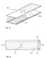
- FIG. 7 shows two mutually displaceable thin glass plates GL1, GL2, for example microscope slide, which are mutually displaceable in the direction of the arrow and which are each partially coated, for example by means of a highly precise lithographic process.
- the coating for GL1 and GL2 is mirror-symmetrical in such a way that a preferably right-angled and sharp-edged angle W1, W2 of the coating remains free and forms the pinhole PH in the case of plates GL1, GL2 lying one above the other. So that the plates do not slide directly onto one another, which can damage the coating, thin Teflon strips TS can be provided on the edges outside the effective area of the pinhole PH on at least one plate, which ensure low-friction sliding and are preferably oriented in the direction of displacement.
- FIG. 8 shows a further embodiment of an adjustable pinhole, consisting of foils FL1-FL4 arranged on lever joints H1-H4.
- the arrangement relates to an arrangement of the film edges according to FIG. 2c.
- 8c shows a complete arrangement in which a pinhole adjustment can be carried out with an arrangement analogous to FIG. 3 by means of a single stepping motor SM.
Landscapes
- Physics & Mathematics (AREA)
- General Physics & Mathematics (AREA)
- Optics & Photonics (AREA)
- Mechanical Light Control Or Optical Switches (AREA)
- Microscoopes, Condenser (AREA)
- Optical Elements Other Than Lenses (AREA)
- Length Measuring Devices By Optical Means (AREA)
- Exposure And Positioning Against Photoresist Photosensitive Materials (AREA)
Priority Applications (1)
| Application Number | Priority Date | Filing Date | Title |
|---|---|---|---|
| EP07022484A EP1882960A3 (fr) | 2002-09-24 | 2003-09-11 | Diaphragme ajustable par translation avec deux substrats transparent partiellement traités |
Applications Claiming Priority (2)
| Application Number | Priority Date | Filing Date | Title |
|---|---|---|---|
| DE10244850A DE10244850A1 (de) | 2002-09-24 | 2002-09-24 | Einstellbares Pinhole |
| DE10244850 | 2002-09-24 |
Related Child Applications (1)
| Application Number | Title | Priority Date | Filing Date |
|---|---|---|---|
| EP07022484A Division EP1882960A3 (fr) | 2002-09-24 | 2003-09-11 | Diaphragme ajustable par translation avec deux substrats transparent partiellement traités |
Publications (3)
| Publication Number | Publication Date |
|---|---|
| EP1403674A2 true EP1403674A2 (fr) | 2004-03-31 |
| EP1403674A3 EP1403674A3 (fr) | 2004-05-26 |
| EP1403674B1 EP1403674B1 (fr) | 2007-11-21 |
Family
ID=31969610
Family Applications (2)
| Application Number | Title | Priority Date | Filing Date |
|---|---|---|---|
| EP07022484A Withdrawn EP1882960A3 (fr) | 2002-09-24 | 2003-09-11 | Diaphragme ajustable par translation avec deux substrats transparent partiellement traités |
| EP03020426A Expired - Lifetime EP1403674B1 (fr) | 2002-09-24 | 2003-09-11 | Trou d'epingle reglable |
Family Applications Before (1)
| Application Number | Title | Priority Date | Filing Date |
|---|---|---|---|
| EP07022484A Withdrawn EP1882960A3 (fr) | 2002-09-24 | 2003-09-11 | Diaphragme ajustable par translation avec deux substrats transparent partiellement traités |
Country Status (4)
| Country | Link |
|---|---|
| US (2) | US7324253B2 (fr) |
| EP (2) | EP1882960A3 (fr) |
| JP (1) | JP2004118190A (fr) |
| DE (2) | DE10244850A1 (fr) |
Cited By (2)
| Publication number | Priority date | Publication date | Assignee | Title |
|---|---|---|---|---|
| EP1897095A2 (fr) * | 2005-06-20 | 2008-03-12 | Bundesanstalt Für Materialforschung Und -Prufung (Bam) | Diaphragme destine a un dispositif de reproduction d'images |
| CN104981726A (zh) * | 2013-02-05 | 2015-10-14 | 皮克斯特隆尼斯有限公司 | 并入有多级快门的显示设备 |
Families Citing this family (7)
| Publication number | Priority date | Publication date | Assignee | Title |
|---|---|---|---|---|
| JP4354207B2 (ja) | 2003-04-15 | 2009-10-28 | オリンパス株式会社 | 顕微鏡装置 |
| JP5228257B2 (ja) * | 2006-12-26 | 2013-07-03 | 日本精工株式会社 | 可視下遠心装置及び観察装置 |
| KR20080078165A (ko) * | 2007-02-22 | 2008-08-27 | 삼성전자주식회사 | 레이저 리페어 시스템 |
| DE102010036790A1 (de) * | 2010-08-02 | 2012-02-02 | Leica Microsystems Cms Gmbh | Einrichtung zur lückenlosen Einstellung von Spektrometer-Spaltbreiten |
| KR20130130779A (ko) | 2010-12-20 | 2013-12-02 | 픽스트로닉스 인코포레이티드 | 감소된 음향 방출을 갖는 mems 광 변조기 어레이들을 위한 시스템들 및 방법들 |
| CN114850216B (zh) * | 2022-07-04 | 2022-10-04 | 太原理工大学 | 一种电控微爆炸成型制备双金属复合板的方法 |
| DE102023001734A1 (de) | 2023-04-28 | 2024-10-31 | PicoQuant Innovations GmbH | Lochblendeneinrichtung mit einer einstellbaren Apertur |
Family Cites Families (16)
| Publication number | Priority date | Publication date | Assignee | Title |
|---|---|---|---|---|
| US2964998A (en) * | 1958-10-03 | 1960-12-20 | Fred J Middlestadt | Precision light aperture arrangement |
| FR2022123A1 (fr) * | 1968-08-14 | 1970-07-31 | Wollnik Hermann | |
| GB1327394A (en) * | 1969-10-23 | 1973-08-22 | Atomic Energy Authority Uk | Adjustable slits |
| US4017162A (en) * | 1973-08-13 | 1977-04-12 | Varian Techtron Pty. Ltd. | Adjustable slit mechanism |
| EP0276337B1 (fr) * | 1987-01-24 | 1989-11-29 | Dr.-Ing. Rudolf Hell GmbH | Arrangement de diaphragmes pour le balayage optoélectronique des documents |
| NL8700496A (nl) * | 1987-02-27 | 1988-09-16 | Stichting Tech Wetenschapp | Continu variabel microdiafragma. |
| US4904055A (en) * | 1988-10-03 | 1990-02-27 | Eastman Kodak Company | Variable aperture formed by linearly movable elements |
| JPH0519206A (ja) * | 1990-10-26 | 1993-01-29 | Toyo Ink Mfg Co Ltd | 光ビームのサイズ制御方法 |
| US5105582A (en) * | 1991-04-17 | 1992-04-21 | Bell Peter M | Cup cutter sharpener |
| JPH04358110A (ja) * | 1991-06-05 | 1992-12-11 | Olympus Optical Co Ltd | 可変ピンホール |
| DE4212077A1 (de) * | 1992-04-10 | 1993-10-14 | Fraunhofer Ges Forschung | Piezoelektrisch verstellbares Ventil und Verfahren zu ihrer Herstellung |
| JPH09159935A (ja) * | 1995-12-12 | 1997-06-20 | Olympus Optical Co Ltd | 可変ピンホール機構 |
| US5907733A (en) * | 1997-11-21 | 1999-05-25 | Nisca Corporation | Exposing aperture device for a camera |
| DE10111465A1 (de) * | 2001-03-09 | 2002-09-12 | Bodenseewerk Geraetetech | Blendenanordnung für ein mikrooptisches System |
| DE10132119A1 (de) * | 2001-07-03 | 2003-01-16 | Claus Bild Und Datentechnik Gm | Motorische Blende für optische Baugruppen |
| DE20205079U1 (de) * | 2002-03-30 | 2002-06-13 | Leica Microsystems | Variable Lochblende und konfokales Scanmikroskop |
-
2002
- 2002-09-24 DE DE10244850A patent/DE10244850A1/de not_active Withdrawn
-
2003
- 2003-09-11 EP EP07022484A patent/EP1882960A3/fr not_active Withdrawn
- 2003-09-11 EP EP03020426A patent/EP1403674B1/fr not_active Expired - Lifetime
- 2003-09-11 DE DE50308633T patent/DE50308633D1/de not_active Expired - Lifetime
- 2003-09-18 JP JP2003326525A patent/JP2004118190A/ja active Pending
- 2003-09-24 US US10/669,394 patent/US7324253B2/en not_active Expired - Fee Related
-
2007
- 2007-10-29 US US11/926,435 patent/US7400433B2/en not_active Expired - Fee Related
Cited By (2)
| Publication number | Priority date | Publication date | Assignee | Title |
|---|---|---|---|---|
| EP1897095A2 (fr) * | 2005-06-20 | 2008-03-12 | Bundesanstalt Für Materialforschung Und -Prufung (Bam) | Diaphragme destine a un dispositif de reproduction d'images |
| CN104981726A (zh) * | 2013-02-05 | 2015-10-14 | 皮克斯特隆尼斯有限公司 | 并入有多级快门的显示设备 |
Also Published As
| Publication number | Publication date |
|---|---|
| JP2004118190A (ja) | 2004-04-15 |
| DE50308633D1 (de) | 2008-01-03 |
| EP1882960A2 (fr) | 2008-01-30 |
| DE10244850A1 (de) | 2004-04-01 |
| EP1403674A3 (fr) | 2004-05-26 |
| US7400433B2 (en) | 2008-07-15 |
| US20040134889A1 (en) | 2004-07-15 |
| EP1882960A3 (fr) | 2008-06-25 |
| US20080049294A1 (en) | 2008-02-28 |
| EP1403674B1 (fr) | 2007-11-21 |
| US7324253B2 (en) | 2008-01-29 |
Similar Documents
| Publication | Publication Date | Title |
|---|---|---|
| DE2361155C2 (de) | Vorrichtung zum Positionieren eines ersten Gegenstandes in bezug auf einen zweiten Gegenstand | |
| DE2854856C2 (fr) | ||
| DE69200553T2 (de) | Beweglicher Objekttisch. | |
| EP0271646B1 (fr) | Dispositif de mesure sans contact d'une distance d'une surface, en particulier pour palper un contour d'une surface d'une pièce d'oeuvre le long d'une trajectoire de mesure | |
| EP1133377A1 (fr) | Dispositif et procede de balayage de la surface d'un objet a l'aide d'un faisceau laser | |
| DE2803375A1 (de) | Vorrichtung zum messen von biegewinkeln bei blechabkantpressen | |
| DE69016576T2 (de) | Zweistrahl-Interferometer für ein Fourier-Spektrometer sowie Antriebsvorrichtung für einen beweglichen Planspiegel dafür. | |
| EP1403674A2 (fr) | Trou d'epingle reglable | |
| DE3390532C2 (de) | Optisches System zur mehrfachen Reflexion | |
| DE2159134B2 (de) | Einrichtung zur interferometrischen messung der verschiebung eines schlittens | |
| DE69902341T2 (de) | Optische Anordnung, insbesondere Spiegel oder Verschlussvorrichtung, mit elektrostatischem Antrieb und variablem Betriebszustand | |
| DE4229507C2 (de) | Mikromechanischer 3-D-Aktor | |
| DE19744938A1 (de) | Optische Positionsmeßeinrichtung | |
| DE10125031A1 (de) | Tischpositioniervorrichtung | |
| DE3102684C2 (fr) | ||
| DE2164607C3 (de) | Vorrichtung zur Erzeugung eines parallel zu sich selbst verschobenen Fahrstrahles | |
| DE69219005T2 (de) | Optischer Kopfantrieb | |
| WO2017178223A1 (fr) | Ensemble de mesure de position et procédé pour faire fonctionner un ensemble de mesure de position | |
| DE20205079U1 (de) | Variable Lochblende und konfokales Scanmikroskop | |
| DE102016125255A1 (de) | Wellenfrontmanipulator und optisches Gerät | |
| WO2004104647A1 (fr) | Stenope reglable | |
| DE2432671A1 (de) | Vorrichtung zum messen und bearbeiten von werkstuecken | |
| DE3820783C2 (fr) | ||
| DE10215178B4 (de) | Vorrichtung und Verfahren zur quantitativen Analyse der Verteilung der kristallographischen Orientierung von Kristalliten in einem Polykristall mit Hilfe von Röntgenstrahlen | |
| DD249989B1 (de) | Feinpositionierende justiervorrichtung |
Legal Events
| Date | Code | Title | Description |
|---|---|---|---|
| PUAI | Public reference made under article 153(3) epc to a published international application that has entered the european phase |
Free format text: ORIGINAL CODE: 0009012 |
|
| 17P | Request for examination filed |
Effective date: 20030911 |
|
| AK | Designated contracting states |
Kind code of ref document: A2 Designated state(s): AT BE BG CH CY CZ DE DK EE ES FI FR GB GR HU IE IT LI LU MC NL PT RO SE SI SK TR |
|
| AX | Request for extension of the european patent |
Extension state: AL LT LV MK |
|
| PUAL | Search report despatched |
Free format text: ORIGINAL CODE: 0009013 |
|
| AK | Designated contracting states |
Kind code of ref document: A3 Designated state(s): AT BE BG CH CY CZ DE DK EE ES FI FR GB GR HU IE IT LI LU MC NL PT RO SE SI SK TR |
|
| AX | Request for extension of the european patent |
Extension state: AL LT LV MK |
|
| AKX | Designation fees paid |
Designated state(s): AT BE BG CH CY CZ DE DK EE ES FI FR GB GR HU IE IT LI LU MC NL PT RO SE SI SK TR |
|
| 17Q | First examination report despatched |
Effective date: 20050113 |
|
| GRAP | Despatch of communication of intention to grant a patent |
Free format text: ORIGINAL CODE: EPIDOSNIGR1 |
|
| RIN1 | Information on inventor provided before grant (corrected) |
Inventor name: BARTZKE, KARLHEINZ Inventor name: WOLLESCHENSKY, RALF Inventor name: KLOPFLEISCH, KARL-HEINZ Inventor name: HOFMANN, JENS |
|
| GRAS | Grant fee paid |
Free format text: ORIGINAL CODE: EPIDOSNIGR3 |
|
| GRAA | (expected) grant |
Free format text: ORIGINAL CODE: 0009210 |
|
| AK | Designated contracting states |
Kind code of ref document: B1 Designated state(s): AT BE BG CH CY CZ DE DK EE ES FI FR GB GR HU IE IT LI LU MC NL PT RO SE SI SK TR |
|
| REG | Reference to a national code |
Ref country code: GB Ref legal event code: FG4D Free format text: NOT ENGLISH |
|
| REG | Reference to a national code |
Ref country code: IE Ref legal event code: FG4D Free format text: LANGUAGE OF EP DOCUMENT: GERMAN |
|
| REG | Reference to a national code |
Ref country code: CH Ref legal event code: EP |
|
| REF | Corresponds to: |
Ref document number: 50308633 Country of ref document: DE Date of ref document: 20080103 Kind code of ref document: P |
|
| GBT | Gb: translation of ep patent filed (gb section 77(6)(a)/1977) |
Effective date: 20080205 |
|
| ET | Fr: translation filed | ||
| PG25 | Lapsed in a contracting state [announced via postgrant information from national office to epo] |
Ref country code: ES Free format text: LAPSE BECAUSE OF FAILURE TO SUBMIT A TRANSLATION OF THE DESCRIPTION OR TO PAY THE FEE WITHIN THE PRESCRIBED TIME-LIMIT Effective date: 20080304 Ref country code: SE Free format text: LAPSE BECAUSE OF FAILURE TO SUBMIT A TRANSLATION OF THE DESCRIPTION OR TO PAY THE FEE WITHIN THE PRESCRIBED TIME-LIMIT Effective date: 20080221 Ref country code: NL Free format text: LAPSE BECAUSE OF FAILURE TO SUBMIT A TRANSLATION OF THE DESCRIPTION OR TO PAY THE FEE WITHIN THE PRESCRIBED TIME-LIMIT Effective date: 20071121 |
|
| NLV1 | Nl: lapsed or annulled due to failure to fulfill the requirements of art. 29p and 29m of the patents act | ||
| PG25 | Lapsed in a contracting state [announced via postgrant information from national office to epo] |
Ref country code: FI Free format text: LAPSE BECAUSE OF FAILURE TO SUBMIT A TRANSLATION OF THE DESCRIPTION OR TO PAY THE FEE WITHIN THE PRESCRIBED TIME-LIMIT Effective date: 20071121 Ref country code: BG Free format text: LAPSE BECAUSE OF FAILURE TO SUBMIT A TRANSLATION OF THE DESCRIPTION OR TO PAY THE FEE WITHIN THE PRESCRIBED TIME-LIMIT Effective date: 20080221 Ref country code: SI Free format text: LAPSE BECAUSE OF FAILURE TO SUBMIT A TRANSLATION OF THE DESCRIPTION OR TO PAY THE FEE WITHIN THE PRESCRIBED TIME-LIMIT Effective date: 20071121 |
|
| PG25 | Lapsed in a contracting state [announced via postgrant information from national office to epo] |
Ref country code: CZ Free format text: LAPSE BECAUSE OF FAILURE TO SUBMIT A TRANSLATION OF THE DESCRIPTION OR TO PAY THE FEE WITHIN THE PRESCRIBED TIME-LIMIT Effective date: 20071121 Ref country code: DK Free format text: LAPSE BECAUSE OF FAILURE TO SUBMIT A TRANSLATION OF THE DESCRIPTION OR TO PAY THE FEE WITHIN THE PRESCRIBED TIME-LIMIT Effective date: 20071121 |
|
| PG25 | Lapsed in a contracting state [announced via postgrant information from national office to epo] |
Ref country code: SK Free format text: LAPSE BECAUSE OF FAILURE TO SUBMIT A TRANSLATION OF THE DESCRIPTION OR TO PAY THE FEE WITHIN THE PRESCRIBED TIME-LIMIT Effective date: 20071121 Ref country code: RO Free format text: LAPSE BECAUSE OF FAILURE TO SUBMIT A TRANSLATION OF THE DESCRIPTION OR TO PAY THE FEE WITHIN THE PRESCRIBED TIME-LIMIT Effective date: 20071121 |
|
| PLBE | No opposition filed within time limit |
Free format text: ORIGINAL CODE: 0009261 |
|
| STAA | Information on the status of an ep patent application or granted ep patent |
Free format text: STATUS: NO OPPOSITION FILED WITHIN TIME LIMIT |
|
| PG25 | Lapsed in a contracting state [announced via postgrant information from national office to epo] |
Ref country code: PT Free format text: LAPSE BECAUSE OF FAILURE TO SUBMIT A TRANSLATION OF THE DESCRIPTION OR TO PAY THE FEE WITHIN THE PRESCRIBED TIME-LIMIT Effective date: 20080421 |
|
| REG | Reference to a national code |
Ref country code: IE Ref legal event code: FD4D |
|
| 26N | No opposition filed |
Effective date: 20080822 |
|
| PG25 | Lapsed in a contracting state [announced via postgrant information from national office to epo] |
Ref country code: IE Free format text: LAPSE BECAUSE OF FAILURE TO SUBMIT A TRANSLATION OF THE DESCRIPTION OR TO PAY THE FEE WITHIN THE PRESCRIBED TIME-LIMIT Effective date: 20071121 |
|
| PG25 | Lapsed in a contracting state [announced via postgrant information from national office to epo] |
Ref country code: GR Free format text: LAPSE BECAUSE OF FAILURE TO SUBMIT A TRANSLATION OF THE DESCRIPTION OR TO PAY THE FEE WITHIN THE PRESCRIBED TIME-LIMIT Effective date: 20080222 |
|
| BERE | Be: lapsed |
Owner name: CARL ZEISS JENA G.M.B.H. Effective date: 20080930 |
|
| PG25 | Lapsed in a contracting state [announced via postgrant information from national office to epo] |
Ref country code: MC Free format text: LAPSE BECAUSE OF NON-PAYMENT OF DUE FEES Effective date: 20080930 Ref country code: EE Free format text: LAPSE BECAUSE OF FAILURE TO SUBMIT A TRANSLATION OF THE DESCRIPTION OR TO PAY THE FEE WITHIN THE PRESCRIBED TIME-LIMIT Effective date: 20071121 |
|
| REG | Reference to a national code |
Ref country code: CH Ref legal event code: PL |
|
| PG25 | Lapsed in a contracting state [announced via postgrant information from national office to epo] |
Ref country code: BE Free format text: LAPSE BECAUSE OF NON-PAYMENT OF DUE FEES Effective date: 20080930 Ref country code: CY Free format text: LAPSE BECAUSE OF FAILURE TO SUBMIT A TRANSLATION OF THE DESCRIPTION OR TO PAY THE FEE WITHIN THE PRESCRIBED TIME-LIMIT Effective date: 20071121 |
|
| PG25 | Lapsed in a contracting state [announced via postgrant information from national office to epo] |
Ref country code: LI Free format text: LAPSE BECAUSE OF NON-PAYMENT OF DUE FEES Effective date: 20080930 Ref country code: AT Free format text: LAPSE BECAUSE OF NON-PAYMENT OF DUE FEES Effective date: 20080911 Ref country code: CH Free format text: LAPSE BECAUSE OF NON-PAYMENT OF DUE FEES Effective date: 20080930 |
|
| PG25 | Lapsed in a contracting state [announced via postgrant information from national office to epo] |
Ref country code: LU Free format text: LAPSE BECAUSE OF NON-PAYMENT OF DUE FEES Effective date: 20080911 Ref country code: HU Free format text: LAPSE BECAUSE OF FAILURE TO SUBMIT A TRANSLATION OF THE DESCRIPTION OR TO PAY THE FEE WITHIN THE PRESCRIBED TIME-LIMIT Effective date: 20080522 |
|
| PG25 | Lapsed in a contracting state [announced via postgrant information from national office to epo] |
Ref country code: TR Free format text: LAPSE BECAUSE OF FAILURE TO SUBMIT A TRANSLATION OF THE DESCRIPTION OR TO PAY THE FEE WITHIN THE PRESCRIBED TIME-LIMIT Effective date: 20071121 |
|
| PG25 | Lapsed in a contracting state [announced via postgrant information from national office to epo] |
Ref country code: IT Free format text: LAPSE BECAUSE OF NON-PAYMENT OF DUE FEES Effective date: 20080930 |
|
| REG | Reference to a national code |
Ref country code: DE Ref legal event code: R082 Ref document number: 50308633 Country of ref document: DE Representative=s name: GEYER, FEHNERS & PARTNER (G.B.R.), DE |
|
| REG | Reference to a national code |
Ref country code: DE Ref legal event code: R081 Ref document number: 50308633 Country of ref document: DE Owner name: CARL ZEISS MICROSCOPY GMBH, DE Free format text: FORMER OWNER: CARL ZEISS JENA GMBH, 07745 JENA, DE Effective date: 20130724 Ref country code: DE Ref legal event code: R082 Ref document number: 50308633 Country of ref document: DE Representative=s name: GEYER, FEHNERS & PARTNER (G.B.R.), DE Effective date: 20130724 |
|
| PGFP | Annual fee paid to national office [announced via postgrant information from national office to epo] |
Ref country code: DE Payment date: 20130919 Year of fee payment: 11 |
|
| PGFP | Annual fee paid to national office [announced via postgrant information from national office to epo] |
Ref country code: GB Payment date: 20130919 Year of fee payment: 11 Ref country code: FR Payment date: 20130919 Year of fee payment: 11 |
|
| REG | Reference to a national code |
Ref country code: DE Ref legal event code: R119 Ref document number: 50308633 Country of ref document: DE |
|
| GBPC | Gb: european patent ceased through non-payment of renewal fee |
Effective date: 20140911 |
|
| REG | Reference to a national code |
Ref country code: DE Ref legal event code: R119 Ref document number: 50308633 Country of ref document: DE Effective date: 20150401 |
|
| REG | Reference to a national code |
Ref country code: FR Ref legal event code: ST Effective date: 20150529 |
|
| PG25 | Lapsed in a contracting state [announced via postgrant information from national office to epo] |
Ref country code: GB Free format text: LAPSE BECAUSE OF NON-PAYMENT OF DUE FEES Effective date: 20140911 Ref country code: DE Free format text: LAPSE BECAUSE OF NON-PAYMENT OF DUE FEES Effective date: 20150401 |
|
| PG25 | Lapsed in a contracting state [announced via postgrant information from national office to epo] |
Ref country code: FR Free format text: LAPSE BECAUSE OF NON-PAYMENT OF DUE FEES Effective date: 20140930 |