EP1405600A1 - Dispositif pour prélever un échantillon corporel - Google Patents
Dispositif pour prélever un échantillon corporel Download PDFInfo
- Publication number
- EP1405600A1 EP1405600A1 EP03292285A EP03292285A EP1405600A1 EP 1405600 A1 EP1405600 A1 EP 1405600A1 EP 03292285 A EP03292285 A EP 03292285A EP 03292285 A EP03292285 A EP 03292285A EP 1405600 A1 EP1405600 A1 EP 1405600A1
- Authority
- EP
- European Patent Office
- Prior art keywords
- housing
- needle
- cannula
- trigger
- sliders
- Prior art date
- Legal status (The legal status is an assumption and is not a legal conclusion. Google has not performed a legal analysis and makes no representation as to the accuracy of the status listed.)
- Granted
Links
Images


Classifications
-
- A—HUMAN NECESSITIES
- A61—MEDICAL OR VETERINARY SCIENCE; HYGIENE
- A61B—DIAGNOSIS; SURGERY; IDENTIFICATION
- A61B10/00—Instruments for taking body samples for diagnostic purposes; Other methods or instruments for diagnosis, e.g. for vaccination diagnosis, sex determination or ovulation-period determination; Throat striking implements
- A61B10/02—Instruments for taking cell samples or for biopsy
- A61B10/0233—Pointed or sharp biopsy instruments
- A61B10/0266—Pointed or sharp biopsy instruments means for severing sample
- A61B10/0275—Pointed or sharp biopsy instruments means for severing sample with sample notch, e.g. on the side of inner stylet
-
- A—HUMAN NECESSITIES
- A61—MEDICAL OR VETERINARY SCIENCE; HYGIENE
- A61B—DIAGNOSIS; SURGERY; IDENTIFICATION
- A61B10/00—Instruments for taking body samples for diagnostic purposes; Other methods or instruments for diagnosis, e.g. for vaccination diagnosis, sex determination or ovulation-period determination; Throat striking implements
- A61B10/02—Instruments for taking cell samples or for biopsy
- A61B2010/0208—Biopsy devices with actuators, e.g. with triggered spring mechanisms
Definitions
- the present invention relates to a device for taking a tissue sample or body organ on a human being or animal to examination purposes.
- Sample collection has become a medical procedure that is increasingly practiced since allows among other operations to diagnose disease states at the following various examinations of the sample taken and to reach, without lesion, deep organs such as the liver and kidneys.
- sampling devices have been developed to meet the demand with the aim of facilitating their use by practitioners and to ensure high operating reliability.
- the object of the invention is to propose a sampling device whose design, structurally simple, allows in particular the practitioner to pass said needle and cannula in an armed position, only hand.
- the sampling device of the type previously described is remarkable, according to the invention, in that said sliders comprise stops which are transversely offset relative to each other to the other and in that said control knob comprises a lug transversely under the action of moving means, and acting sequentially on said staggered stops to bring the one after the other said sliders in the rear position.
- a single command button allows the Sequential loading of the needle and cannula in two distinct movements: a first movement of the button from an initial position, which brings for example the cannulated slide in the armed position and, after returning said button to the initial position, a second translational motion that brings the needle slider into position army.
- the use of the device is simple and easy since the practitioner can arm it with one hand with his thumb.
- said moving means may comprise a spring disposed transversely between said button and said pin and allowing the passage of the latter from a retracted position for which one of said slides is moved in the rear position via its abutment, at a output position for which the other slider is moved into position rear via its staggered stop, and an inclined ramp, provided inside said housing and which brings said pin from its extended position to its position returned, when returning to the initial position of said button.
- said inclined ramp ends with an edge side end on which applies, in the initial position of said button, said lug compressing its spring, and which is located at the same level as the stop of the slide to move first.
- the ergot is maintained in position retracted and engages the stop of the slider corresponding immediately the movement of the control button.
- the pin is linked to said button, by example, by a slide connection and can slide transversely via it under the action of the moving means.
- said cannula slide and its spring are located on the front side of said housing and are brought first in the rear position, armed via said pin, while said needle slide and its spring are coaxially located on the rear side of said housing and are moved in second in rear position, armed, moving said slides and springs being limited by fixed tabs secured to said housing.
- said control button is mounted longitudinally sliding through an oblong opening of said housing and a spring disposed longitudinally connects said housing audit button to remind spontaneously the latter in its initial position, against the corresponding front edge of said opening.
- said blocking means comprise at least one elastically deformable hook tab of each slider, and a corresponding fixed stop provided inside said housing and on which engages the bracket hook hook corresponding when it arrives in the rear position.
- said triggering mechanism of said shot of sampling it advantageously comprises, on said housing, a trigger front and rear trigger can be operated independently of each other and acting on said blocking means.
- the practitioner can use one or the other of said triggers to trigger the shot.
- said forward and reverse triggers are mechanically connected between them by a connecting rod arranged inside said housing.
- said rear trigger includes a push button with return spring and with a leg arranged in projection in said housing to release said locking means said needle slide, and said needle slide is furthermore equipped with a tab arranged projecting to act on said locking means of said cannula slide, as a result of its displacement towards the position before.
- said front trigger may include a pivoting lever around an axis of said housing orthogonal to its longitudinal axis, said connecting rod connecting said lever of the trigger before said push button the rear trigger.
- the device comprises security to render said triggering mechanism inoperative.
- said triggering mechanism consists of a notch formed in said housing and wherein said forward trigger can be received as a result of a transverse displacement. The trigger mechanism is then immobilized.
- said housing is preferably composed of two half-shells assembled together along a longitudinal plane.
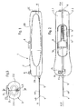
- Figures 1, 2 and 3 are respectively external views in plane, from above and from the side of an exemplary embodiment of the sampling according to the invention.
- FIG. 4 is an exploded perspective view of said device showing its different components.
- FIGS. 6A, 6B, 6C, 6D, 6E, 6F, 6G and 6H are views in section along the line I-I of FIGS. 5A, 5B, 5C, 5D, 5E, 5F, 5G and 5H showing the different stages of operation of the control of said device.
- FIGS. 7A, 7B, 7C, 7D and 7E are perspective views, delimited by a rectangular frame of said operating knob acting on the stops of the sliders in the positions occupied by the device in FIGS. 5A to 5E respectively.
- the sampling device 1 of a body tissue sample shown in Figures 1 to 3, comprises a similar gripping housing 2 to a handle and whose outer shape substantially parallelepiped rounded, anatomical, allowing the practitioner to grasp appropriately and easily use the device with one hand.
- the front trigger 8 and the rear trigger 9 of a firing trigger mechanism of said needle and cannula are accessible from the outside of the housing and are respectively provided on the top housing, near its front face 2A, and on its rear face 2C.
- the housing of gripping 2 consists of two half-shells 2.1, 2.2 assembled between them to define a median longitudinal plane P-P of said housing, and a inner housing 10 inside which are mounted the different components of the sampling device 1 which will be described below in FIGS. 4, 5A, 6A and 7A.
- the slide 12 with cannula 5 is at the front of the housing 2, while that the slider 11 with needle 4 is located behind, that is to say turned towards the back of the housing, its needle 4 through the cannula 5 and the slider associated 12 to the output of its distal tapered tip 4B of the cannula.
- Springs 14, 15 are also associated respectively with the slides being arranged along the longitudinal axis X-X of the sliders.
- the cannulated slide 12 abuts against a fixed front leg 2D housing under the action of the spring 15 disposed between the slider and a fixed intermediate leg 2E of the housing, and the needle slide 11 is pressed against the fixed intermediate leg 2E, on the other side, under the action spring 14 disposed between the slider and a third fixed rear leg 2F of the housing.
- These springs are compression type and identical. These three legs are for example protruding from the half-shell 2.1 of the housing, transversely at its longitudinal plane P-P.
- said slides 11, 12 occupy a forward position in the housing 2, for which the needle 4 and cannula 5 are in the initial rest position, unarmed, largely out front panel 2A housing.
- the slides 11, 12 cooperate, in their movement, with 2G guides from half-shells 2.1 and 2.2 and engaging in respective lateral grooves 11A, 12A thereof.
- the button control 6 makes it possible to bring the sliders 11 into the rear position, 12, against the respective springs 14, 15, rear position for which the needle 4 and cannula 5 are then in retracted position armed, ready for sampling, as will be seen later in look at Figure 5D.
- the latter are provided with respective stops 16, 17 which are transversely offset with respect to the other, and the control button comprises a lug 18 movable transversely, that is, perpendicular to the plane P-P, under the action of displacement means and which can act sequentially on the stops.
- the stop 17 is standing vertically at the rear end of the cannulated slide 12 and present, for example, an angled L-shape in which can engage the movable pin 18 associated with the control button 6.
- the other stop 16 is erected vertically on the slider 11 with needle, in being located substantially at the same height as the abutment 17 of the slider 12 (FIGS. 5A, 7A), but shifted transversely of said stop 17 ( Figures 6A, 7A).
- the stop 16 of the needle slide is also bent for a safe and reliable engagement of said pin 18. This last protrude vertically downward from said button 6 to just come to the level slides and it comes from a base 19 housed inside the button and mounted transversely sliding therein by a connection to slide 20.
- the means for moving the lug 18 advantageously comprise a spring 21 arranged transversely against a side wall 6A of the button and a recess 19A formed in the base, and a inclined ramp 22 provided inside the housing and secured to the half-shell 2.1 from which it comes.
- the spring 21 of the compression type ensures the passage of the lug 18 of a retracted position, for which the slider 12 is moved by its abutment 17 towards its rear position, at an extended position, for which the other slider 11 is moved backwards via its stop 16 transversely offset from that of the slide 12.
- the ramp 22 returns said pin 18 in the retracted position, compressing the spring 21, when returning to the initial position of the button 6.
- FIGS. 6A and 7A show in particular that the inclined ramp 22 ends with an end edge 22A parallel to the X-X axis, on which applies the lug in the initial position of the button, and which is advantageously located in the extension of the corresponding side 17A of the stop 17 in L.
- control button 6 is maintained in initial position by a tension spring 23 connecting it to the half-shell 2.1 of the housing and bringing it against the front edge 7A of the opening oblong 7 of said housing.
- each slide 11, 12 comprises, in this example embodiment, an elastically deformable longitudinal tab 11B, 12B terminated by a hook 11C, 12C, adapted to engage with a stop corresponding fixed 2J, 2H transversely protruding from the half-shell 2.1 of the housing.
- the trigger before 8 and the rear trigger 9 can be operated independently each other according to the preference of the practitioner, while being advantageously mechanically connected to each other to influence the means of blocking 11B, 11C, 2J - 12B, 12C, 2H in the rear position of the slides.
- the front trigger 8 is derived from a lever 8A pivoted about a 2K axis located in front of the half-shell and arranged orthogonally to the X-X axis or to the P-P longitudinal plane of the housing 2.
- the rear trigger 9 it is of the push-button type 9A with longitudinal displacement, with a return spring 9B provided therebetween and the rear face 2C of the housing, and provided with a protruding leg 9C longitudinally inside said housing.
- This tab 9C is intended for come into contact with the blocking means 11B, 11C to erase them and release the rear slide 11, which also comprises a longitudinal tab 11D, opposite to that 11B, to act on the locking means 12B, 12C of the slider 12 in the housing, as will be seen later.
- Swing lever 8A of the front trigger and the push button 9A of the rear trigger are connected by a rod or rod 24 current to the inside of the housing and engaging by its ends in corresponding holes 8B, 9E provided in the lever 8A and the tab 9C of the pushbutton.
- a rod or rod 24 current to the inside of the housing and engaging by its ends in corresponding holes 8B, 9E provided in the lever 8A and the tab 9C of the pushbutton.
- the trigger before 8 is slightly offset transversely to the longitudinal plane P-P housing 1.
- This transverse shift is a security for the trigger mechanism that can only be made active if the practitioner brings it back in the longitudinal plane P-P.
- this security is defined by a notch 2L extending transversely the opening 2M formed in the top of the housing for the passage of the lever 8A of the front trigger, which lever can slide transversely on its axis 2K to be brought into the slot 2L or out of it by the practitioner.
- This trigger before 8 (and, therefore, the trigger mechanism) is made operational only if the practitioner moves it transversely towards the longitudinal plane according to the arrow F3.
- sampling device 1 The operation of the sampling device 1 according to the invention will now be described.
- the arming of the device 1 is done with one hand and sequentially, by two successive movements towards the rear of the control button 6 which acts, at first, on the slider 12 with cannula 5 and, secondly, on the needle slide 11 4.
- the practitioner can then proceed with the sampling shot, as the show FIGS. 5F, 5G and 5H.
- the shot can be fired either with the trigger before 8, making pivoting its lever 8A according to the arrow F1 of FIG. 5F about the axis 2K, with the rear trigger 9, pushing the push-button forward 9A according to the arrow F2.
- the practitioner will have brought the trigger before 8 in the longitudinal plane P-P, acting for that on this according to the arrow F3 of Figures 2 and 3, which makes the lever slide 8A on its 2K axis and away from the notch 2L. Security is then erased and the triggering mechanism is made operational.
- FIG. 5F shows that the sloping end of the tab 9D 9C longitudinal pushbutton is applied on the hook 11C of the elastic tab 11B of the slider 11 to deform elastically and disengage the hook 11C from the corresponding fixed stop 2J.
- the triggers 8, 9 return to the initial position under the action of the return spring 9B.
- the practitioner then removes the needle and cannula device 1 of the patient.
Landscapes
- Health & Medical Sciences (AREA)
- Life Sciences & Earth Sciences (AREA)
- Surgery (AREA)
- Animal Behavior & Ethology (AREA)
- Biomedical Technology (AREA)
- Heart & Thoracic Surgery (AREA)
- Medical Informatics (AREA)
- Molecular Biology (AREA)
- Pathology (AREA)
- Engineering & Computer Science (AREA)
- General Health & Medical Sciences (AREA)
- Public Health (AREA)
- Veterinary Medicine (AREA)
- Infusion, Injection, And Reservoir Apparatuses (AREA)
- Measurement Of The Respiration, Hearing Ability, Form, And Blood Characteristics Of Living Organisms (AREA)
- Surgical Instruments (AREA)
Abstract
Description
- une aiguille dont l'extrémité distale forme un évidement apte à recevoir ledit échantillon ;
- une canule entourant coaxialement ladite aiguille, lesdites aiguille et canule pouvant coulisser l'une par rapport à l'autre ;
- des coulisseaux associés respectivement auxdites aiguille et canule ;
- des ressorts associés respectivement auxdits coulisseaux ;
- un boítier de préhension de forme allongée, définissant un logement interne à l'intérieur duquel sont agencés en série, selon un axe longitudinal dudit boítier, lesdits coulisseaux pouvant coulisser entre une position avant dans le boítier, pour laquelle lesdites aiguille et canule sont en position de repos, prêtes à être armées pour un tir de prélèvement, et une position arrière, pour laquelle lesdites aiguille et canule sont en position rétractée armée, prêtes pour ledit tir ;
- un bouton de commande pour amener en position arrière lesdits coulisseaux à l'encontre desdits ressorts respectifs ;
- des moyens de blocage desdits coulisseaux en position arrière ; et
- un mécanisme de déclenchement pour effacer lesdits moyens de blocage et entraíner, sous l'action desdits ressorts, le déplacement en position avant desdits coulisseaux et le tir de prélèvement desdites aiguille et canule.
- coulisseaux à aiguille et à canule en position repos ;
- premier déplacement du bouton de commande pour l'armement du coulisseau à canule ;
- retour du bouton de commande en position initiale ;
- second déplacement du bouton de commande pour l'armement du coulisseau à aiguille ;
- retour du bouton de commande en position initiale ;
- commande du tir par le mécanisme de déclenchement et action sur les moyens de blocage du coulisseau à aiguille ;
- sortie du coulisseau à aiguille et action sur les moyens de blocage du coulisseau à canule ; et
- sortie du coulisseau à canule.
- les coulisseaux 11, 12 occupent la position avant dans le boítier, en butée contre les pattes avant et intermédiaire respectives 2B, 2E, sous l'action des ressorts 14, 15, position pour laquelle les canule 5 et aiguille 4 sont en position initiale sortie, de repos ; la pointe biseautée de la canule 5 recouvrant l'évidement 4A de l'aiguille ;
- le bouton de commande 6 est en position initiale avant par l'action du ressort 23, contre le bord avant 7A de l'ouverture du boítier 2 ;
- l'ergot 18 se trouve en contact avec le bord d'extrémité latéral 22A de la rampe inclinée ; et
- le mécanisme de déclenchement 8, 9 est inactif.
Claims (13)
- Dispositif pour prélever des échantillons corporels, du type comportant :caractérisé en ce que lesdits coulisseaux (11, 12) comportent des butées (16, 17) qui sont transversalement décalées l'une par rapport à l'autre et en ce que ledit bouton de commande (6) comprend un ergot (18) mobile transversalement sous l'action de moyens de déplacement, et agissant séquentiellement sur lesdites butées décalées pour amener l'un après l'autre lesdits coulisseaux en position arrière.une aiguille (4) dont l'extrémité distale forme un évidement apte à recevoir ledit échantillon ;une canule (5) entourant coaxialement ladite aiguille, lesdites aiguille et canule pouvant coulisser l'une par rapport à l'autre ;des coulisseaux (11, 12) associés respectivement auxdites aiguille et canule ;des ressorts (14, 15) associés respectivement auxdits coulisseaux ;un boítier de préhension (2) de forme allongée, définissant un logement interne (10) à l'intérieur duquel sont agencés en série, selon un axe longitudinal dudit boítier, lesdits coulisseaux (11, 12) pouvant coulisser entre une position avant dans le boítier, pour laquelle lesdites aiguille (4) et canule (5) sont en position de repos, prêtes à être armées pour un tir de prélèvement, et une position arrière, pour laquelle lesdites aiguille et canule sont en position rétractée armée, prêtes pour ledit tir ;un bouton de commande (6) pour amener en position arrière lesdits coulisseaux à l'encontre desdits ressorts respectifs ;des moyens de blocage desdits coulisseaux (11, 12) en position arrière ; etun mécanisme de déclenchement (8, 9) pour effacer lesdits moyens de blocage et entraíner, sous l'action desdits ressorts, le déplacement en position avant desdits coulisseaux et le tir de prélèvement desdites aiguille et canule,
- Dispositif selon la revendication 1,
caractérisé en ce que lesdits moyens de déplacement comprennent un ressort (21) disposé transversalement entre ledit bouton (6) et ledit ergot (18) et permettant le passage de ce dernier d'une position rentrée pour laquelle l'un (11) desdits coulisseaux est déplacé en position arrière via sa butée (16), à une position sortie pour laquelle l'autre coulisseau (12) est déplacé en position arrière via sa butée décalée (17), et une rampe inclinée (22), prévue à l'intérieur dudit boítier et qui ramène ledit ergot de sa position sortie vers sa position rentrée, lors du retour en position initiale dudit bouton. - Dispositif selon la revendication 2,
caractérisé en ce que ladite rampe inclinée (22) se termine par un bord d'extrémité latéral (22A) sur lequel s'applique, en position initiale dudit bouton, ledit ergot (18) comprimant son ressort, et qui est situé au même niveau que la butée (16) du coulisseau (11) à déplacer en premier. - Dispositif selon l'une quelconque des revendications 1 à 3,
caractérisé en ce que ledit ergot (18) est lié audit bouton (6) par une liaison à glissière (20) et peut coulisser transversalement, via celle-ci, sous l'action des moyens de déplacement. - Dispositif selon l'une quelconque des revendications 1 à 4,
caractérisé en ce que ledit coulisseau (12) à canule et son ressort (15) sont situés du côté avant dudit boítier (2) et sont amenés en premier en position arrière, armée via ledit ergot, tandis que ledit coulisseau (11) à aiguille et son ressort (14) sont coaxialement situés du côté arrière et déplacés en second en position arrière, armée, le déplacement desdits coulisseaux et ressorts étant limité par des pattes fixes solidaires dudit boítier. - Dispositif selon l'une quelconque des revendications 1 à 5,
caractérisé en ce que ledit bouton de commande (6) est monté longitudinalement coulissant à travers une ouverture oblongue (7) dudit boítier et en ce qu'un ressort (23) disposé longitudinalement relie ledit boítier audit bouton pour rappeler spontanément ce dernier dans sa position initiale, contre le bord avant correspondant de ladite ouverture. - Dispositif selon l'une quelconque des revendications 1 à 6,
caractérisé en ce que lesdits moyens de blocage comportent au moins une patte à crochet élastiquement déformable (11B, 11C - 12B, 12C) issue de chaque coulisseau, et une butée fixe correspondante (2H-2J) prévue à l'intérieur dudit boítier et sur laquelle s'engage la patte à crochet du coulisseau correspondant quand celui-ci arrive en position arrière. - Dispositif selon l'une quelconque des revendications 1 à 7,
caractérisé en ce que ledit mécanisme de déclenchement dudit tir de prélèvement comporte, sur ledit boítier, une gâchette avant (8) et une gâchette arrière (9) actionnables indépendamment l'une de l'autre et agissant sur lesdits moyens de blocage. - Dispositif selon la revendication 8,
caractérisé en ce que lesdites gâchettes avant et arrière sont reliées mécaniquement entre elles par une tige de liaison (24) située à l'intérieur dudit boítier. - Dispositif selon l'une des revendications 8 et 9,
caractérisé en ce que ladite gâchette arrière (9) comprend un bouton-poussoir (9A) avec ressort de rappel (9B) et muni d'une patte (9C) agencée en saillie dans ledit boítier pour libérer lesdits moyens de blocage (11B, 11C) dudit coulisseau à aiguille, et en ce que ledit coulisseau à aiguille (11) est équipé d'une patte de déblocage (11D) agencée en saillie pour agir sur lesdits moyens de blocage (12B, 12C, 2H) dudit coulisseau (12) à canule, par suite de son déplacement vers la position avant. - Dispositif selon l'une quelconque des revendications 8 à 10,
caractérisé en ce que ladite gâchette avant (8) comprend un levier pivotant (8A) autour d'un axe (2K) dudit boítier orthogonal à son axe longitudinal, ladite tige de liaison (24) reliant ledit levier de la gâchette avant audit bouton-poussoir de la gâchette arrière. - Dispositif selon l'une quelconque des revendications 8 à 11,
caractérisé en ce qu'il comprend une sécurité pour rendre inopérationnel ledit mécanisme de déclenchement (8, 9), ladite sécurité consistant en une encoche (2L) ménagée dans ledit boítier et dans laquelle peut être reçue ladite gâchette avant (8) par suite d'un déplacement transversal. - Dispositif selon l'une quelconque des revendications 1 à 12,
caractérisé en ce que ledit boítier se compose de deux demi-coques assemblées entre elles le long d'un plan longitudinal.
Applications Claiming Priority (2)
| Application Number | Priority Date | Filing Date | Title |
|---|---|---|---|
| FR0212234A FR2845266B1 (fr) | 2002-10-03 | 2002-10-03 | Dispositif pour prelever un echantillon corporel |
| FR0212234 | 2002-10-03 |
Publications (2)
| Publication Number | Publication Date |
|---|---|
| EP1405600A1 true EP1405600A1 (fr) | 2004-04-07 |
| EP1405600B1 EP1405600B1 (fr) | 2009-07-15 |
Family
ID=31985414
Family Applications (1)
| Application Number | Title | Priority Date | Filing Date |
|---|---|---|---|
| EP03292285A Expired - Lifetime EP1405600B1 (fr) | 2002-10-03 | 2003-09-16 | Dispositif pour prélever un échantillon corporel |
Country Status (6)
| Country | Link |
|---|---|
| US (1) | US7153275B2 (fr) |
| EP (1) | EP1405600B1 (fr) |
| JP (1) | JP4195847B2 (fr) |
| DE (1) | DE60328347D1 (fr) |
| ES (1) | ES2329351T3 (fr) |
| FR (1) | FR2845266B1 (fr) |
Cited By (3)
| Publication number | Priority date | Publication date | Assignee | Title |
|---|---|---|---|---|
| CN104797200A (zh) * | 2012-11-21 | 2015-07-22 | C·R·巴德公司 | 芯针活检装置 |
| WO2016037192A1 (fr) * | 2014-09-05 | 2016-03-10 | Jj Dogs, Llc | Perfectionnements apportés à un dispositif de micro-biopsie au trocart |
| US11130004B2 (en) | 2005-11-10 | 2021-09-28 | Cianna Medical, Inc. | Brachytherapy apparatus and methods for using them |
Families Citing this family (90)
| Publication number | Priority date | Publication date | Assignee | Title |
|---|---|---|---|---|
| US6355021B1 (en) * | 1998-07-14 | 2002-03-12 | Maersk Medical A/S | Medical puncturing device |
| USD526409S1 (en) | 1998-07-14 | 2006-08-08 | Unomedical A/S | Medical puncturing device |
| US6830562B2 (en) * | 2001-09-27 | 2004-12-14 | Unomedical A/S | Injector device for placing a subcutaneous infusion set |
| ITTO20011228A1 (it) * | 2001-12-28 | 2003-06-28 | Cane Srl | Contenitore per ago monouso. |
| AU2003208296A1 (en) * | 2002-02-12 | 2003-09-04 | Unomedial A/S | Infusion device with needle shield |
| US7258680B2 (en) * | 2002-09-02 | 2007-08-21 | Unomedical A/S | Device for subcutaneous administration of a medicament to a patient |
| DK1556124T3 (da) * | 2002-09-02 | 2008-02-18 | Unomedical As | Apparatur og fremgangsmåde til justering af en infusionsslanges længde |
| US7115112B2 (en) * | 2002-09-02 | 2006-10-03 | Unomedical A/S | Device for subcutaneous administration of a medicament to a patient and tubing for same |
| US20040051019A1 (en) * | 2002-09-02 | 2004-03-18 | Mogensen Lasse Wesseltoft | Apparatus for and a method of adjusting the length of an infusion tube |
| EP2008690B1 (fr) | 2002-09-10 | 2013-11-06 | Cianna Medical, Inc. | Appareil de curiethérapie |
| DK200201823A (da) | 2002-11-26 | 2004-05-27 | Maersk Medical As | Forbindelsesstykke for en slangeforbindelse |
| US20040158202A1 (en) * | 2003-02-12 | 2004-08-12 | Soren Jensen | Cover |
| US7070580B2 (en) * | 2003-04-01 | 2006-07-04 | Unomedical A/S | Infusion device and an adhesive sheet material and a release liner |
| USD579541S1 (en) | 2003-10-15 | 2008-10-28 | Unomedical A/S | Medical insertion device |
| USD554253S1 (en) | 2003-10-15 | 2007-10-30 | Unomedical A/S | Medical infusion device |
| USD576267S1 (en) | 2003-10-15 | 2008-09-02 | Unomedical A/S | Medical infusion device |
| ATE424228T1 (de) | 2004-03-26 | 2009-03-15 | Unomedical As | Infusionsset |
| US8062250B2 (en) | 2004-08-10 | 2011-11-22 | Unomedical A/S | Cannula device |
| US7662082B2 (en) * | 2004-11-05 | 2010-02-16 | Theragenics Corporation | Expandable brachytherapy device |
| US7867199B2 (en) | 2004-12-10 | 2011-01-11 | Unomedical A/S | Inserter |
| US7470237B2 (en) * | 2005-01-10 | 2008-12-30 | Ethicon Endo-Surgery, Inc. | Biopsy instrument with improved needle penetration |
| US7985199B2 (en) | 2005-03-17 | 2011-07-26 | Unomedical A/S | Gateway system |
| CA2602169A1 (fr) * | 2005-03-21 | 2006-09-28 | Unomedical A/S | Tampon de montage, dispositif adhesif comprenant un tel tampon et procedes d'application de tels dispositifs sur un patient |
| ITMO20050143A1 (it) * | 2005-06-10 | 2006-12-11 | Hs Hospital Service Spa | Dispositivo per biopsia. |
| MX2007016062A (es) | 2005-06-28 | 2008-03-10 | Unomedical As | Empaquetamiento para juego de infusion y metodo para aplicar un juego de infusion. |
| JP4575257B2 (ja) * | 2005-09-06 | 2010-11-04 | オリンパスメディカルシステムズ株式会社 | 組織生検針装置 |
| ATE480278T1 (de) | 2005-09-12 | 2010-09-15 | Unomedical As | Einfürungssystem für ein infusionsset mit einem ersten und zweiten federeinheit |
| WO2007053823A2 (fr) | 2005-10-31 | 2007-05-10 | Biolucent, Inc. | Appareil de brachythérapie et ses méthodes d'utilisation |
| US7887476B2 (en) | 2005-11-10 | 2011-02-15 | Cianna Medical, Inc. | Helical brachytherapy apparatus and methods of using same |
| USD655807S1 (en) | 2005-12-09 | 2012-03-13 | Unomedical A/S | Medical device |
| DE602006006477D1 (de) | 2005-12-23 | 2009-06-04 | Unomedical As | Verabreichungsgerät |
| AU2007219546B8 (en) | 2006-02-28 | 2012-07-05 | Unomedical A/S | Inserter for infusion part and infusion part provided with needle protector |
| US7465278B2 (en) * | 2006-03-29 | 2008-12-16 | Ethicon Endo-Surgery, Inc. | Device for minimally invasive internal tissue removal |
| US20070232953A1 (en) * | 2006-03-31 | 2007-10-04 | Ethicon Endo-Surgery, Inc. | MRI biopsy device |
| JP5213851B2 (ja) | 2006-06-02 | 2013-06-19 | シアンナ・メディカル・インコーポレイテッド | 拡張可能な小線源療法装置 |
| WO2007140783A2 (fr) | 2006-06-07 | 2007-12-13 | Unomedical A/S | Appareil à insérer |
| KR20090028701A (ko) | 2006-06-09 | 2009-03-19 | 우노메디컬 에이/에스 | 장착 패드 |
| US7909842B2 (en) * | 2006-06-15 | 2011-03-22 | Abbott Diabetes Care Inc. | Lancing devices having depth adjustment assembly |
| RU2443436C2 (ru) | 2006-08-02 | 2012-02-27 | Уномедикал А/С | Канюльное и доставочное устройство |
| CA2665326C (fr) | 2006-10-08 | 2016-01-19 | Cianna Medical, Inc. | Appareil de curietherapie telescopique |
| EP1917990A1 (fr) | 2006-10-31 | 2008-05-07 | Unomedical A/S | Ensemble de perfusion |
| WO2008149850A1 (fr) | 2007-06-08 | 2008-12-11 | Konica Minolta Holdings, Inc. | Processus de production d'un élément d'affichage électrochimique et élément d'affichage électrochimique |
| EP2155311B1 (fr) | 2007-06-20 | 2013-01-02 | Unomedical A/S | Procédé et dispositif de fabrication d'un cathéter |
| EP2185224A1 (fr) | 2007-07-03 | 2010-05-19 | Unomedical A/S | Dispositif d'introduction présentant deux états d'équilibre stables |
| RU2010104457A (ru) * | 2007-07-10 | 2011-08-20 | Уномедикал А/С (Dk) | Устройство ввода с двумя пружинами |
| NZ582226A (en) | 2007-07-18 | 2011-12-22 | Unomedical As | Insertion device with a pivoting action from a first to a second position and longitudinal action to a third position in the direction of insertion. |
| EP2200677A1 (fr) | 2007-09-17 | 2010-06-30 | ICU Medical, Inc. | Dispositifs d'insertion pour dispositifs de perfusion |
| US8517907B2 (en) | 2007-12-16 | 2013-08-27 | Cianna Medical, Inc. | Expandable brachytherapy apparatus and methods for using them |
| RU2010137844A (ru) | 2008-02-13 | 2012-03-20 | Уномедикал А/С (Dk) | Уплотнение между канюльной частью и путем прохождения текучей среды |
| CA2715667A1 (fr) | 2008-02-20 | 2009-08-27 | Unomedical A/S | Dispositif d'insertion munie d'une piece mobile dans le sens horizontal |
| US8029526B2 (en) * | 2008-08-14 | 2011-10-04 | Abbott Diabetes Care Inc. | Cocking mechanism for lancing device |
| WO2010022103A1 (fr) | 2008-08-18 | 2010-02-25 | Cianna Medical, Inc. | Appareil de curiethéraphie, systèmes et procédés d'utilisation |
| CN102256657A (zh) | 2008-12-22 | 2011-11-23 | 犹诺医药有限公司 | 包括粘合垫的医疗器械 |
| JP2013500099A (ja) | 2009-07-30 | 2013-01-07 | ウノメディカル・アー/エス | 水平方向の可動部材を備えた挿入デバイス |
| CN102548598B (zh) | 2009-08-07 | 2014-09-17 | 犹诺医药有限公司 | 具有传感器和一个或多个插管的传送装置 |
| US8814775B2 (en) | 2010-03-18 | 2014-08-26 | Cianna Medical, Inc. | Expandable brachytherapy apparatus and methods for using them |
| CA2792138A1 (fr) | 2010-03-30 | 2011-10-06 | Unomedical A/S | Dispositif medical |
| ES2426246T3 (es) | 2010-07-16 | 2013-10-22 | Coloplast A/S | Dispositivo para tomar al menos una muestra de tejido |
| EP2407112B1 (fr) | 2010-07-16 | 2020-05-06 | Coloplast A/S | Dispositif de prelevement d'au moins un echantillon de tissu |
| US9883919B2 (en) | 2010-07-21 | 2018-02-06 | Cianna Medical, Inc. | Brachytherapy apparatus, systems, and methods for using them |
| EP2433663A1 (fr) | 2010-09-27 | 2012-03-28 | Unomedical A/S | Système d'insertion |
| EP2436412A1 (fr) | 2010-10-04 | 2012-04-04 | Unomedical A/S | Canule d'arroseur |
| US9067063B2 (en) | 2010-11-03 | 2015-06-30 | Cianna Medical, Inc. | Expandable brachytherapy apparatus and methods for using them |
| US8858465B2 (en) * | 2011-04-14 | 2014-10-14 | Devicor Medical Products, Inc. | Biopsy device with motorized needle firing |
| US20130023790A1 (en) * | 2011-07-19 | 2013-01-24 | Schaeffer Jeremy R | Biopsy device |
| ITBO20110467A1 (it) * | 2011-07-29 | 2013-01-30 | Biopsybell S R L | Dispositivo automatico monouso per biospie |
| EP2763723B1 (fr) | 2011-10-05 | 2016-04-13 | Unomedical A/S | Introducteur pour insertion simultanée de plusieurs éléments transcutanés |
| EP2583715A1 (fr) | 2011-10-19 | 2013-04-24 | Unomedical A/S | Système de tube de perfusion et procédé de fabrication |
| US9440051B2 (en) | 2011-10-27 | 2016-09-13 | Unomedical A/S | Inserter for a multiplicity of subcutaneous parts |
| WO2013107692A1 (fr) | 2012-01-16 | 2013-07-25 | Coloplast A/S | Dispositif pour le prélèvement d'au moins un échantillon de tissu |
| WO2013107693A1 (fr) | 2012-01-16 | 2013-07-25 | Coloplast A/S | Dispositif pour le prélèvement d'au moins un échantillon de tissu |
| EP2804536B1 (fr) * | 2012-01-16 | 2018-04-11 | Coloplast A/S | Dispositif pour le prélèvement d'au moins un échantillon de tissu |
| ES2808427T3 (es) | 2012-01-16 | 2021-02-26 | Coloplast As | Dispositivo para tomar al menos una muestra de un tejido |
| US20140378865A1 (en) * | 2012-01-16 | 2014-12-25 | Coloplast A/S | Device for Taking at Least One Sample of Tissue |
| USD735332S1 (en) | 2013-03-06 | 2015-07-28 | C. R. Bard, Inc. | Biopsy device |
| USD737440S1 (en) | 2013-03-07 | 2015-08-25 | C. R. Bard, Inc. | Biopsy device |
| USD735333S1 (en) | 2013-06-26 | 2015-07-28 | C. R. Bard, Inc. | Biopsy device |
| EP2862520A1 (fr) * | 2013-10-16 | 2015-04-22 | AprioMed AB | Dispositif de biopsie |
| CN105520756B (zh) * | 2014-09-29 | 2020-03-31 | 德昌电机(深圳)有限公司 | 医疗设备用驱动装置 |
| JP6239197B2 (ja) * | 2015-06-10 | 2017-11-29 | オリンパス株式会社 | 生検針 |
| ITUB20152694A1 (it) * | 2015-07-31 | 2017-01-31 | Pietro Musicco | Pistola automatica per biopsia |
| US10709429B2 (en) * | 2016-12-05 | 2020-07-14 | Argon Medical Devices Inc. | Biopsy device handle |
| WO2019232526A1 (fr) * | 2018-06-02 | 2019-12-05 | G.I. Windows, Inc. | Systèmes, dispositifs et procédés de distribution et de positionnement de dispositifs de compression d'anastomose magnétique |
| IT201800006731A1 (it) * | 2018-06-27 | 2019-12-27 | Dispositivo di prelievo di campioni di tessuto biologico | |
| WO2020028303A1 (fr) * | 2018-07-31 | 2020-02-06 | Devicor Medical Products, Inc. | Dispositif de biopsie à aiguille centrale pour collecter de multiples échantillons en une seule insertion |
| WO2020185961A1 (fr) * | 2019-03-11 | 2020-09-17 | MFr Technologies, Inc. | Dispositif de carottage de tissu |
| US12419620B2 (en) | 2019-08-22 | 2025-09-23 | Argon Medical Devices, Inc. | Core-severing cannula for biopsy devices |
| CN113499130B (zh) * | 2021-08-24 | 2024-09-10 | 中国人民解放军联勤保障部队第九〇〇医院 | 一种防刺伤胸腔内部器官的穿刺器 |
| CN113768550B (zh) * | 2021-09-18 | 2023-09-15 | 德林医疗科技(武汉)有限公司 | 一种活检针装置及其单次上膛击发机构 |
| CN116636883B (zh) * | 2023-04-06 | 2025-08-26 | 长沙汇顶医疗科技有限责任公司 | 一种一键连续击发全自动活检针 |
Citations (4)
| Publication number | Priority date | Publication date | Assignee | Title |
|---|---|---|---|---|
| EP0238461A1 (fr) * | 1986-02-19 | 1987-09-23 | C.R. Bard, Inc. | Dispositif pour prélever des échantillons de tissu |
| US4958625A (en) * | 1989-07-18 | 1990-09-25 | Boston Scientific Corporation | Biopsy needle instrument |
| US5842999A (en) * | 1996-07-31 | 1998-12-01 | C.R. Bard, Inc. | Automated tissue sampling device |
| US5951489A (en) * | 1997-01-09 | 1999-09-14 | Allegiance Healthcare Corporation | Biopsy surgical appliance |
Family Cites Families (3)
| Publication number | Priority date | Publication date | Assignee | Title |
|---|---|---|---|---|
| DE3924291C2 (de) | 1989-07-22 | 2000-07-13 | Bip Acquisition Company Inc | Biopsiekanäle zur Entnahme von Gewebeproben |
| IT1285597B1 (it) * | 1996-03-07 | 1998-06-18 | Gallini Srl | Dispositivo automatico ad ago per biopsia |
| US7022085B2 (en) * | 2002-11-20 | 2006-04-04 | Scimed Life Systems, Inc. | Medical instrument |
-
2002
- 2002-10-03 FR FR0212234A patent/FR2845266B1/fr not_active Expired - Fee Related
-
2003
- 2003-09-16 DE DE60328347T patent/DE60328347D1/de not_active Expired - Lifetime
- 2003-09-16 EP EP03292285A patent/EP1405600B1/fr not_active Expired - Lifetime
- 2003-09-16 ES ES03292285T patent/ES2329351T3/es not_active Expired - Lifetime
- 2003-09-25 US US10/669,432 patent/US7153275B2/en not_active Expired - Lifetime
- 2003-10-02 JP JP2003344606A patent/JP4195847B2/ja not_active Expired - Fee Related
Patent Citations (5)
| Publication number | Priority date | Publication date | Assignee | Title |
|---|---|---|---|---|
| EP0238461A1 (fr) * | 1986-02-19 | 1987-09-23 | C.R. Bard, Inc. | Dispositif pour prélever des échantillons de tissu |
| US4699154A (en) * | 1986-02-19 | 1987-10-13 | Radiplast Ab | Tissue sampling device |
| US4958625A (en) * | 1989-07-18 | 1990-09-25 | Boston Scientific Corporation | Biopsy needle instrument |
| US5842999A (en) * | 1996-07-31 | 1998-12-01 | C.R. Bard, Inc. | Automated tissue sampling device |
| US5951489A (en) * | 1997-01-09 | 1999-09-14 | Allegiance Healthcare Corporation | Biopsy surgical appliance |
Cited By (4)
| Publication number | Priority date | Publication date | Assignee | Title |
|---|---|---|---|---|
| US11130004B2 (en) | 2005-11-10 | 2021-09-28 | Cianna Medical, Inc. | Brachytherapy apparatus and methods for using them |
| CN104797200A (zh) * | 2012-11-21 | 2015-07-22 | C·R·巴德公司 | 芯针活检装置 |
| WO2016037192A1 (fr) * | 2014-09-05 | 2016-03-10 | Jj Dogs, Llc | Perfectionnements apportés à un dispositif de micro-biopsie au trocart |
| JP2017529983A (ja) * | 2014-09-05 | 2017-10-12 | ペイブ,エルエルシー | 完全コア生検装置のための改善 |
Also Published As
| Publication number | Publication date |
|---|---|
| ES2329351T3 (es) | 2009-11-25 |
| FR2845266B1 (fr) | 2004-12-17 |
| JP2004121852A (ja) | 2004-04-22 |
| EP1405600B1 (fr) | 2009-07-15 |
| DE60328347D1 (de) | 2009-08-27 |
| FR2845266A1 (fr) | 2004-04-09 |
| US7153275B2 (en) | 2006-12-26 |
| US20040068231A1 (en) | 2004-04-08 |
| JP4195847B2 (ja) | 2008-12-17 |
Similar Documents
| Publication | Publication Date | Title |
|---|---|---|
| EP1405600B1 (fr) | Dispositif pour prélever un échantillon corporel | |
| EP1850906B1 (fr) | Dispositif d'injection d'un implant solide ou semi-solide | |
| EP1827565B1 (fr) | Dispositif pour la retro-injection d'un implant | |
| KR100674398B1 (ko) | 분리형 커넥터를 구비한 란싱 디바이스 | |
| TWI266033B (en) | Gun system and accessory thereof | |
| EP1737529B1 (fr) | Dispositif pour l'introduction d'un catheter avec cage de securite anti-pique a lame flexible | |
| FR2498444A1 (fr) | Instrument d'agrafage chirurgical a jeter apres usage | |
| EP0329580B1 (fr) | Eplucheur à légumes ou à fruits | |
| FR2572946A1 (fr) | Vehicule jouet a pousser | |
| EP0781083B1 (fr) | Dispositif de guidage, d'entraínement et de verrouillage d'un tiroir d'équipement électrique ou électronique dans une armoire | |
| CA2261192A1 (fr) | Extracteur chirurgical | |
| JP5416108B2 (ja) | ランセット切開装置 | |
| KR20190083385A (ko) | 채혈기 | |
| FR2462145A1 (fr) | Dispositif de ligature de conduits tubulaires tels que des trompes de fallope | |
| FR2697434A1 (fr) | Dispositif pour actionner le poussoir d'une seringue en vue d'y créer une dépression, système et procédé en faisant application pour la mise en place temporaire d'un cathéter et/ou d'un fil guide. | |
| WO2000067644A1 (fr) | Appareil de distribution et de pose d'attaches chirurgicales en 'i' | |
| EP4424392B1 (fr) | Dispositif d'appui sur le sol comprenant un baton et une dragonne | |
| JP3118277U (ja) | 引出しスライドレールの自動開放装置 | |
| EP1615524B1 (fr) | Dispositif formant pince a epiler | |
| EP1586727B1 (fr) | Mécanisme d'ouverture/fermeture de portière de véhicule automobile | |
| EP0800189B1 (fr) | Dispositif d'actionnement pour appareil électrique tel que disjoncteur-moteur | |
| FR2720226A1 (fr) | Instrument du type fusil pour la neutralisation d'un poisson ferré. | |
| WO2007014904A1 (fr) | Pistolet à biopsie automatique | |
| FR2991220A1 (fr) | Appareil de fixation, par tir indirect, a securite de fonctionnement | |
| FR2956341A1 (fr) | Couteau de securite |
Legal Events
| Date | Code | Title | Description |
|---|---|---|---|
| PUAI | Public reference made under article 153(3) epc to a published international application that has entered the european phase |
Free format text: ORIGINAL CODE: 0009012 |
|
| AK | Designated contracting states |
Kind code of ref document: A1 Designated state(s): AT BE BG CH CY CZ DE DK EE ES FI FR GB GR HU IE IT LI LU MC NL PT RO SE SI SK TR |
|
| AX | Request for extension of the european patent |
Extension state: AL LT LV MK |
|
| 17P | Request for examination filed |
Effective date: 20040526 |
|
| AKX | Designation fees paid |
Designated state(s): DE ES GB IT |
|
| RAP1 | Party data changed (applicant data changed or rights of an application transferred) |
Owner name: COLOPLAST A/S |
|
| 17Q | First examination report despatched |
Effective date: 20080610 |
|
| GRAP | Despatch of communication of intention to grant a patent |
Free format text: ORIGINAL CODE: EPIDOSNIGR1 |
|
| GRAS | Grant fee paid |
Free format text: ORIGINAL CODE: EPIDOSNIGR3 |
|
| GRAA | (expected) grant |
Free format text: ORIGINAL CODE: 0009210 |
|
| AK | Designated contracting states |
Kind code of ref document: B1 Designated state(s): DE ES GB IT |
|
| REG | Reference to a national code |
Ref country code: GB Ref legal event code: FG4D Free format text: NOT ENGLISH |
|
| REF | Corresponds to: |
Ref document number: 60328347 Country of ref document: DE Date of ref document: 20090827 Kind code of ref document: P |
|
| REG | Reference to a national code |
Ref country code: ES Ref legal event code: FG2A Ref document number: 2329351 Country of ref document: ES Kind code of ref document: T3 |
|
| PLBE | No opposition filed within time limit |
Free format text: ORIGINAL CODE: 0009261 |
|
| STAA | Information on the status of an ep patent application or granted ep patent |
Free format text: STATUS: NO OPPOSITION FILED WITHIN TIME LIMIT |
|
| 26N | No opposition filed |
Effective date: 20100416 |
|
| PGFP | Annual fee paid to national office [announced via postgrant information from national office to epo] |
Ref country code: IT Payment date: 20100922 Year of fee payment: 8 |
|
| PGFP | Annual fee paid to national office [announced via postgrant information from national office to epo] |
Ref country code: ES Payment date: 20101018 Year of fee payment: 8 |
|
| PG25 | Lapsed in a contracting state [announced via postgrant information from national office to epo] |
Ref country code: IT Free format text: LAPSE BECAUSE OF NON-PAYMENT OF DUE FEES Effective date: 20110916 |
|
| REG | Reference to a national code |
Ref country code: ES Ref legal event code: FD2A Effective date: 20130418 |
|
| PG25 | Lapsed in a contracting state [announced via postgrant information from national office to epo] |
Ref country code: ES Free format text: LAPSE BECAUSE OF NON-PAYMENT OF DUE FEES Effective date: 20110917 |
|
| PGFP | Annual fee paid to national office [announced via postgrant information from national office to epo] |
Ref country code: GB Payment date: 20210927 Year of fee payment: 19 |
|
| PGFP | Annual fee paid to national office [announced via postgrant information from national office to epo] |
Ref country code: DE Payment date: 20220629 Year of fee payment: 20 |
|
| GBPC | Gb: european patent ceased through non-payment of renewal fee |
Effective date: 20220916 |
|
| REG | Reference to a national code |
Ref country code: DE Ref legal event code: R071 Ref document number: 60328347 Country of ref document: DE |
|
| PG25 | Lapsed in a contracting state [announced via postgrant information from national office to epo] |
Ref country code: GB Free format text: LAPSE BECAUSE OF NON-PAYMENT OF DUE FEES Effective date: 20220916 |