EP1406025B1 - Joint d'étanchéité à lèvres élastiques pour arbre rotatif - Google Patents
Joint d'étanchéité à lèvres élastiques pour arbre rotatif Download PDFInfo
- Publication number
- EP1406025B1 EP1406025B1 EP03021351A EP03021351A EP1406025B1 EP 1406025 B1 EP1406025 B1 EP 1406025B1 EP 03021351 A EP03021351 A EP 03021351A EP 03021351 A EP03021351 A EP 03021351A EP 1406025 B1 EP1406025 B1 EP 1406025B1
- Authority
- EP
- European Patent Office
- Prior art keywords
- seal
- sealing lip
- axial
- lip
- seal according
- Prior art date
- Legal status (The legal status is an assumption and is not a legal conclusion. Google has not performed a legal analysis and makes no representation as to the accuracy of the status listed.)
- Expired - Lifetime
Links
- 238000007789 sealing Methods 0.000 claims abstract description 221
- 239000013013 elastic material Substances 0.000 claims abstract description 6
- 238000005452 bending Methods 0.000 claims description 16
- 239000000314 lubricant Substances 0.000 claims description 16
- XLYOFNOQVPJJNP-UHFFFAOYSA-N water Substances O XLYOFNOQVPJJNP-UHFFFAOYSA-N 0.000 claims description 11
- 239000011248 coating agent Substances 0.000 claims description 8
- 238000000576 coating method Methods 0.000 claims description 8
- 238000003780 insertion Methods 0.000 claims description 8
- 230000037431 insertion Effects 0.000 claims description 8
- 230000002787 reinforcement Effects 0.000 claims description 7
- 229920001971 elastomer Polymers 0.000 claims description 6
- 239000000463 material Substances 0.000 claims description 6
- 239000003566 sealing material Substances 0.000 claims description 6
- 238000002485 combustion reaction Methods 0.000 claims description 5
- 239000000806 elastomer Substances 0.000 claims description 5
- 239000004810 polytetrafluoroethylene Substances 0.000 claims description 4
- 229920001343 polytetrafluoroethylene Polymers 0.000 claims description 4
- 229920006168 hydrated nitrile rubber Polymers 0.000 claims description 3
- 230000007704 transition Effects 0.000 claims description 3
- 238000000926 separation method Methods 0.000 claims description 2
- NBVXSUQYWXRMNV-UHFFFAOYSA-N fluoromethane Chemical compound FC NBVXSUQYWXRMNV-UHFFFAOYSA-N 0.000 claims 1
- 238000009434 installation Methods 0.000 description 8
- 238000005096 rolling process Methods 0.000 description 7
- 239000011324 bead Substances 0.000 description 3
- 230000000694 effects Effects 0.000 description 3
- 230000035515 penetration Effects 0.000 description 3
- 239000002826 coolant Substances 0.000 description 2
- 239000000498 cooling water Substances 0.000 description 2
- 238000010790 dilution Methods 0.000 description 2
- 239000012895 dilution Substances 0.000 description 2
- 239000004519 grease Substances 0.000 description 2
- 238000010438 heat treatment Methods 0.000 description 2
- 239000007788 liquid Substances 0.000 description 2
- 230000035945 sensitivity Effects 0.000 description 2
- 239000000243 solution Substances 0.000 description 2
- 235000012773 waffles Nutrition 0.000 description 2
- 238000010521 absorption reaction Methods 0.000 description 1
- 230000006978 adaptation Effects 0.000 description 1
- 230000002411 adverse Effects 0.000 description 1
- 230000001419 dependent effect Effects 0.000 description 1
- 230000001066 destructive effect Effects 0.000 description 1
- 230000001627 detrimental effect Effects 0.000 description 1
- 229920001973 fluoroelastomer Polymers 0.000 description 1
- 239000012535 impurity Substances 0.000 description 1
- 230000001050 lubricating effect Effects 0.000 description 1
- 238000005461 lubrication Methods 0.000 description 1
- 210000004072 lung Anatomy 0.000 description 1
- 230000013011 mating Effects 0.000 description 1
- 238000013021 overheating Methods 0.000 description 1
- 239000002245 particle Substances 0.000 description 1
- 230000008092 positive effect Effects 0.000 description 1
- 239000007787 solid Substances 0.000 description 1
Images


Classifications
-
- F—MECHANICAL ENGINEERING; LIGHTING; HEATING; WEAPONS; BLASTING
- F16—ENGINEERING ELEMENTS AND UNITS; GENERAL MEASURES FOR PRODUCING AND MAINTAINING EFFECTIVE FUNCTIONING OF MACHINES OR INSTALLATIONS; THERMAL INSULATION IN GENERAL
- F16C—SHAFTS; FLEXIBLE SHAFTS; ELEMENTS OR CRANKSHAFT MECHANISMS; ROTARY BODIES OTHER THAN GEARING ELEMENTS; BEARINGS
- F16C33/00—Parts of bearings; Special methods for making bearings or parts thereof
- F16C33/72—Sealings
- F16C33/76—Sealings of ball or roller bearings
- F16C33/78—Sealings of ball or roller bearings with a diaphragm, disc, or ring, with or without resilient members
- F16C33/784—Sealings of ball or roller bearings with a diaphragm, disc, or ring, with or without resilient members mounted to a groove in the inner surface of the outer race and extending toward the inner race
- F16C33/7843—Sealings of ball or roller bearings with a diaphragm, disc, or ring, with or without resilient members mounted to a groove in the inner surface of the outer race and extending toward the inner race with a single annular sealing disc
- F16C33/7853—Sealings of ball or roller bearings with a diaphragm, disc, or ring, with or without resilient members mounted to a groove in the inner surface of the outer race and extending toward the inner race with a single annular sealing disc with one or more sealing lips to contact the inner race
-
- F—MECHANICAL ENGINEERING; LIGHTING; HEATING; WEAPONS; BLASTING
- F16—ENGINEERING ELEMENTS AND UNITS; GENERAL MEASURES FOR PRODUCING AND MAINTAINING EFFECTIVE FUNCTIONING OF MACHINES OR INSTALLATIONS; THERMAL INSULATION IN GENERAL
- F16C—SHAFTS; FLEXIBLE SHAFTS; ELEMENTS OR CRANKSHAFT MECHANISMS; ROTARY BODIES OTHER THAN GEARING ELEMENTS; BEARINGS
- F16C33/00—Parts of bearings; Special methods for making bearings or parts thereof
- F16C33/72—Sealings
- F16C33/76—Sealings of ball or roller bearings
- F16C33/78—Sealings of ball or roller bearings with a diaphragm, disc, or ring, with or without resilient members
- F16C33/784—Sealings of ball or roller bearings with a diaphragm, disc, or ring, with or without resilient members mounted to a groove in the inner surface of the outer race and extending toward the inner race
- F16C33/7859—Sealings of ball or roller bearings with a diaphragm, disc, or ring, with or without resilient members mounted to a groove in the inner surface of the outer race and extending toward the inner race with a further sealing element
-
- F—MECHANICAL ENGINEERING; LIGHTING; HEATING; WEAPONS; BLASTING
- F16—ENGINEERING ELEMENTS AND UNITS; GENERAL MEASURES FOR PRODUCING AND MAINTAINING EFFECTIVE FUNCTIONING OF MACHINES OR INSTALLATIONS; THERMAL INSULATION IN GENERAL
- F16J—PISTONS; CYLINDERS; SEALINGS
- F16J15/00—Sealings
- F16J15/16—Sealings between relatively-moving surfaces
- F16J15/32—Sealings between relatively-moving surfaces with elastic sealings, e.g. O-rings
- F16J15/3248—Sealings between relatively-moving surfaces with elastic sealings, e.g. O-rings provided with casings or supports
- F16J15/3252—Sealings between relatively-moving surfaces with elastic sealings, e.g. O-rings provided with casings or supports with rigid casings or supports
- F16J15/3256—Sealings between relatively-moving surfaces with elastic sealings, e.g. O-rings provided with casings or supports with rigid casings or supports comprising two casing or support elements, one attached to each surface, e.g. cartridge or cassette seals
- F16J15/3264—Sealings between relatively-moving surfaces with elastic sealings, e.g. O-rings provided with casings or supports with rigid casings or supports comprising two casing or support elements, one attached to each surface, e.g. cartridge or cassette seals the elements being separable from each other
-
- F—MECHANICAL ENGINEERING; LIGHTING; HEATING; WEAPONS; BLASTING
- F16—ENGINEERING ELEMENTS AND UNITS; GENERAL MEASURES FOR PRODUCING AND MAINTAINING EFFECTIVE FUNCTIONING OF MACHINES OR INSTALLATIONS; THERMAL INSULATION IN GENERAL
- F16C—SHAFTS; FLEXIBLE SHAFTS; ELEMENTS OR CRANKSHAFT MECHANISMS; ROTARY BODIES OTHER THAN GEARING ELEMENTS; BEARINGS
- F16C2360/00—Engines or pumps
- F16C2360/42—Pumps with cylinders or pistons
Definitions
- the present invention relates to a seal assembly that transforms a seal formed as a shaft lip seal, and a bearing ring with a groove and a rotating shaft.
- the seal made of elastic material is intended for fluid-tight separation of pressure chambers , in particular used in roller bearings of water pumps for internal combustion engines.
- the shaft lip seal is arranged between two relatively moving components.
- the torsionally rigid, preferably in a groove, used seal forms a first radial sealing lip, which is followed by a second axial sealing lip.
- the radial, at least one sealing edge having sealing lip supported by a spring means is supported on the aligned in the direction of an axis of symmetry of the seal shaft.
- the additional axial sealing lip is supported in an installed position via at least one sealing edge on a contact surface aligned perpendicular to the axis of symmetry of the seal.
- a reinforcement is provided, which is preferably integrated in a radial section of the seal and is enclosed on at least one side by the elastic sealing material.
- a shaft lip seal with a previously mentioned structure is known, for example, from DE 38 43 337 A1.
- the axial sealing lip of this known seal is supported in the installed position with a large axial overlap on the contact surface of a centrifugal sleeve.
- the relatively short length of the axial sealing lip in conjunction with the large axial overlap between the axial lip and the contact surface leads to an increased contact pressure, combined with an excessively high overheating.
- the sealing lip in the support area "burn" can, which negatively affects the functionality of the seal.
- the invention is based on the object of designing a seal in order to reduce the sensitivity of the sealing lip cover regardless of the temperature and the speed of the cooperating with the sealing lips of the seal component.
- the axial sealing lip is in the untensioned, dead, not installed state of the seal, aligned with the axis of symmetry at an angle of attack of ⁇ 35 °.
- the axial sealing lip extends in the de-energized state of the seal over a length of ⁇ 1.4 mm.
- an installation position for the shaft lip seal is provided, in which adjusts an overlap of 0.05 to 0.55 mm between the axial sealing lip and the associated contact surface or sealing surface.
- the measures according to the invention effectively increase the sealing resistance of the axial sealing lip in the supporting region, which improves the function and the service life of the axial sealing lip and thus of the seal.
- a hardness of ⁇ 75 Shore A is additionally provided for the sealing material, which has a positive effect on the elasticity of the axial sealing lip.
- the axial sealing lip is spaced from the sealing edge provided with an angled portion.
- the additional bend of the axial lip causes a further increase in the elasticity.
- the additional bend can be aligned both radially outwards and radially inwards.
- ⁇ inclination angle
- the angle of inclination " ⁇ " for the angled section extends at an angle ⁇ 60 ° at right angles to the symmetry axis of the seal.
- the axial lip may have an end angled away from the axis of symmetry radially outwardly facing away portion.
- the angled end portion of the axial lip includes a pitch angle " ⁇ " ⁇ 40 °, based on a radially aligned to the axis of symmetry leg.
- the invention includes in the region of an angling, a transition between the angle of attack on the one hand and the pitch angle or the inclination angle of the axial seal on the other hand, an annular recess or groove.
- This recess which can also be referred to as a relief groove, can be provided both on the inside and on the outside of the axial seal.
- the groove arranged on the inside on the axial sealing lip can advantageously be used as a lubricant reservoir.
- the geometric design of the seal according to the invention further provides a defined wall thickness profile.
- the wall thickness tapers from the sealing edge of the radial sealing lip to the free end of ⁇ 0.9 to ⁇ 0.2 mm.
- Such a designed sealing lip represents an optimum between a sufficient strength or rigidity on the one hand and a desired high elasticity on the other hand.
- waffling is suitable as a structured contact surface.
- the waffle forms a geometric structure, which is preferably circular arc-like, introduced locally into the contact surface or which may alternatively be arranged protruding out of the contact surface.
- the reduced contact area reduces the heat input into the axial lip.
- the structured contact surface favors the absorption of lubricant and thus ensures a lubrication film required for the service life of the sealing lip between the sealing edge of the axial lip and the associated contact surface.
- the invention includes an axial sealing lip whose end face is provided with a structure. This measure also leads to a desired reduced contact surface of the axial lip with respect to the associated contact surface.
- a coating is furthermore provided at least in the contact region of the axial sealing lip with the associated contact surface.
- a PTFE coating of the sealing edge face or the free end of the axial lip is suitable.
- the contact surface also provided a PTFE coating.
- both the contact surface and the end face of the axial lip can be friction-reduced coated.
- the sealing lip is provided on the inside at the end face directed to the contact surface with swirl ribs.
- the arrangement of these spin ribs is such that a desired return of the lubricant sets, which moves in the direction of the sealing gap, which adjusts an improvement of the seal.
- a direction of rotation independent installation of the seal for this purpose, for example, an aligned in the direction of the axis of symmetry of the seal arrow structure, which ensures regardless of the direction of rotation always a return of the lubricant.
- the shaft lip seal according to the invention is advantageously associated in the installed state of a centrifugal sleeve, which together effectively seal an annular area between an outer roller bearing ring and a shaft.
- the centrifugal sleeve is fixed in position and rotationally fixed to the shaft and forms the contact surface for the axial sealing lip of the Welienlippendichtung.
- the invention includes a centrifugal sleeve which additionally comprises a cylindrical section.
- the lateral surface of the cylindrical, the shaft enclosing portion of the centrifugal sleeve forms a contact surface for the radial sealing lip and the radial board of the centrifugal sleeve, the contact surface for the axial sealing lip of the inventive shaft lip seal.
- the cylindrical portion of the centrifugal sleeve is provided at least on the outside with a circumferential insertion bevel.
- This measure simplifies a sequential installation of the components, seal and centrifugal sleeve, in which after assembly of the seal, the shaft including the associated centrifugal sleeve is inserted axially into the rolling bearing.
- the insertion bevel allows a non-destructive installation of the radial sealing lip, since it is radially expanded by an axial feed of the centrifugal sleeve by means of the insertion and can take without damage and risk of tearing, the mounting position on the lateral surface of the cylindrical portion of the centrifugal sleeve.
- the radial sealing lip and / or the axial sealing lip with two or more sealing edges.
- a sealing lip having a plurality of sealing edges effects a stepped, optimized seal.
- it makes sense to form the respective sealing lip so that the sealing edges are supported with different forces.
- the sealing edge which has a lower supporting force, to assume the function of a pre-seal which prevents the penetration of impurities or larger particles into the downstream sealing zone defined by the sealing edge and the contact surface and thus improves the sealing quality.
- the invention includes arranging the pre-seal so that it extends to the associated contact surface while maintaining a gap dimension.
- the gap is designed or defined so that the pre-lip prevents the penetration of grease into the gap, however, allows oil to enter, to form a lubricant film required for the life of the sliding arranged sealing lip.
- This structure is suitable, for example, for heavily loaded, rotating at high speeds waves and thus rolling bearings, for which a lubricant is provided as a lubricant, whereby the special sealing lip structure, consisting of a grinding and a non-abrasive sealing edge, the lubricant used, the oil for pressurizing the abrasive sealing lip can be withdrawn.
- the inventive design of the shaft lip seal further relates to the design of the spring means, which supports the non-positive support of the radial sealing lip.
- a spring means a hose spring is preferably provided whose diameter is "d" ⁇ 1.1 mm. This small diameter allows a space-optimized designed hose spring, and thus does not affect the design of the axial sealing lip according to the invention.
- the optimized diameter of the hose spring a low spring mass, which proves positive especially for installation situations in which the radial sealing lip is supported on a shaft which rotates at a high speed, which due to the low spring mass swinging and thus detrimental Lifting the sealing lip from the lateral surface of the shaft is omitted.
- the invention further includes as a spring means a radially biased, slotted snap ring.
- a spring means a radially biased, slotted snap ring.
- a snap ring with a rectangular profile which in the installed state radially aligned with the lateral surface of the shaft, only a small axial space in the region of the sealing edge of the radial sealing lip is required.
- an elastomer in particular HNBR is provided.
- a heat-resistant fluororubber such as FPM or HFC. Regardless of the aforementioned sealing materials, these have a hardness of ⁇ 75 Shore A.
- the shaft lip seal according to the invention is particularly suitable for sealing a roller bearing, which is intended for a water pump of an internal combustion engine.
- the seal according to the invention has the task of effectively sealing an annular region between a bearing ring enclosing the rolling bearing outside and the pump shaft.
- the seal arranged in a groove of the bearing ring lip seal is supported by the sealing edge of a radial sealing lip on the lateral surface of the shaft or a cylindrical portion of the arranged on the shaft centrifugal sleeve.
- the further axially aligned sealing lip of the seal according to the invention is slidably supported on a radial leg of the centrifugal sleeve or a contact surface of the shaft.
- the individual features of the characterizing part of claim 1, such as defined angle of attack of the axial sealing lip, increased length of the axial sealing lip and a concrete indication of an axial overlap, which defines the extent of the unstressed, stress-free sealing lip compared to the installation position, are preferably suitable for the application in a water pump.
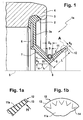
- the seal 1 shows a designed as a wave lip seal seal 1 a in a half section.
- the seal 1 a produced from an elastic material, preferably an elastomer, is positionally positioned with a bead 2 in a force-locking and form-fitting manner in a groove 3 of a bearing ring 4.
- the seal 1 a forms a radial portion which comprises a disk-like reinforcement 6 for stiffening.
- the reinforcement 6 is covered on at least one side by the elastic material of the seal 1 a.
- the seal 1 a forms a laterally staggered, in the direction of the symmetry axis 5 inclined radial sealing lip 7, the sealing edge 8 in the installed state of the seal 1 a sealingly on a lateral surface, preferably a rotating shaft, is supported.
- the sealing edge 8 is assigned as a spring means a hose spring 9, which is inserted into an annular groove 10 of the sealing lip 7, the radial support force of the sealing lip 7 increases.
- the radial sealing lip 7 is adjoined by an axial sealing lip 11a, which is aligned at an angle of attack " ⁇ " with respect to the axis of symmetry 5.
- the free end of the sealing lip 11 forms the sealing edge 12, which is sealingly supported in an installed position sealingly against a contact surface, a shaft shoulder or a separate component rotating with the shaft.
- the seal 1 a includes various measures to improve the elasticity of the axial sealing lip 11 a in particular.
- a defined position of the sealing lip 11a is provided in particular to the axis of symmetry 5 in an angle of attack " ⁇ ", which is aligned in an angle bracket " ⁇ " ⁇ 35 °.
- the axial sealing lip 11a extends over a length "L” of ⁇ 1.4 mm.
- the sealing lip 11a tapers continuously, starting from a dimension "S1" ⁇ 0.8 mm between the inner circumference of the hose spring 11 and the sealing edge 8 to the wall thickness "S2" ⁇ 0.2 mm at the free end of the sealing lip 11a.
- a space-optimized hose spring 9 or worm spring is further provided, the diameter of which is "D” ⁇ 1.3 mm.
- the tube spring 9 is inserted into an annular groove 10 whose "dimension""D o " exceeds the diameter dimension "D".
- FIG. 1a shows in an enlarged scale the detail "A", the free end of the axial sealing lip 11a.
- at least one end face 13 of the sealing edge 12 is structured, whereby the contact surface of the sealing edge 12 is reduced, associated with a reduced heat input from the contact surface in the sealing lip 11 a, which has an advantageous effect on the wear and the life of the seal 1 a.
- a friction-reducing coating for this purpose, for example, a PTFE coating is suitable.
- FIG. 1 b shows the view "H" according to FIG. 1 a and illustrates a structure 14 mounted on the inside of the axial sealing lip 11 a, designed as a alternating swirl.
- This designed as a V-shaped structure 14 improves the sealing quality of the axial sealing lip 11a by a lubricant that accumulates on the inside of the axial sealing lip 11a, when installed can not move unhindered radially outwards but undergoes a deflection.
- Figures 2 to 4 show the gaskets 1 b to 1 d, the structure of which largely coincides with the seal 1 a according to FIG. Corresponding components are therefore provided with the same reference numerals. The following descriptions therefore relate in particular to the differences from the seal 1 a.
- the seal 1b shown in FIG. 2 comprises the axial sealing lip 11b, which forms sections 15b, 16b.
- An angled section 16b which is inclined at an inclination angle " ⁇ " to the axis of symmetry 5, adjoins the first section 15b, which runs at the angle of attack " ⁇ " to the axis of symmetry 5.
- a bending joint 17b is formed between the sections 15b, 16b.
- the bending joint 17b has on the inside, on the axial sealing lip 11b a circumferential groove 18b, whereby a conscious material dilution of the sealing lip 11b sets, which improves the elasticity of the sealing lip 11b in particular those of the angled portion 16b in the installed state.
- FIG. 2 a shows the seal 1 b with a sealing lip 11 e, which is alternatively designed in FIG.
- the flexure hinge 17e does not include a fillet, all other features are consistent.
- the axial sealing lip 11c of the seal 1c comprises the sections 15c, 16c between which the bending joint 17c is provided.
- the bending joint 17c has a circumferential groove 18c arranged on the outside of the sealing lip 11c.
- the bending joint 17 c is preferably arranged so that in the uninstalled, dead state of the seal 1 c, the bending joint 17 c at a distance "Z 1 " from the sealing edge 8 of the radial sealing lip is, wherein the distance "Z 1 " ⁇ 0.5 of the distance "Z” corresponds, which indicates the axial distance between the sealing edge 8 and the end face 13 of the axial sealing lip 11c.
- Figure 3 includes further information.
- the inner diameter is advantageously "d” ⁇ 16 mm in the dead state of the seal 1c.
- the diameter dimension “d s ", which defines the inner diameter of the tube spring 9, is ⁇ 17 mm.
- the dimension “B” determining the seal width is ⁇ 3.2 mm.
- An overhang “b 1 " ⁇ 0.15 mm defines the axial distance between the reinforcement 6 and the bead 2.
- FIG. 4 shows the seal 1d, whose axial sealing lip 11d has an end section 16d which faces away from the symmetry axis 5 at a pitch angle "Y".
- the bending joint 11 d of the axial sealing lip 11 d is formed by a provided on the outside of the sealing lip 11 d circumferential groove 18 d.
- the seal 1a shows the seal 1a in the installed state, for sealing an annular gap, which adjusts between the bearing ring 4 and a rotating shaft 19, in particular a rotating pump shaft of a water pump.
- the seal 1a separates two pressure chambers, an intended for receiving the rolling elements 21 oil chamber 20 and a water chamber 22 which is acted upon by the cooling medium, in particular cooling water of an internal combustion engine.
- the sealing lips of the seal 1 a are assigned to a centrifugal sleeve 23, which is positioned on the shaft 19 and rotates with this component.
- the sealing edge 8 of the radial sealing lip 7 is supported non-positively, supported by the hose spring 9 on the lateral surface 24 of a cylindrical portion 25 of the centrifugal sleeve 23 from.
- the associated additional axial sealing lip 11 a of the seal 1 a is supported on a radial, perpendicular to the axis of symmetry 5 aligned portion 26 of the centrifugal sleeve 23 from.
- a defined axial overlap "X 2 " between the axial sealing lip 11 a and the radial bearing surface 27 of the section 26 of the centrifugal sleeve 23 is a defined mounting position, characterized by the dimension "X 1 " between the bearing ring 4 and the centrifugal sleeve 23 is provided.
- the determination of the axial overlap "X 2 " in conjunction with the constructive measures, which relate in particular to the axial sealing lip 11a, allows optimal contact of the sealing lip 11a on the centrifugal sleeve 23.
- the contact surface is at least partially structured in the area of the sealing lip support.
- a waffle 28 which has axially protruding from the contact surface 27 surveys, which can alternatively be introduced axially into the contact surface 27 is suitable.
- the thereby adjusting smaller contact area between the axial sealing lip 11a and the contact surface 27 reduces the friction and also allows the inclusion of lubricant or a lubricant that is used to build an oil film or a lubricant film between the contact surface 27 and the sealing edge 12 of the axial sealing lip 11a is required.
- a sequential installation is preferably provided, in which first the seal 1 a is inserted into the groove 3, before the centrifugal sleeve 23 is axially supplied.
- the cylindrical section 25 of the centrifugal sleeve 23 is provided with an insertion bevel 31 for this purpose.
- the under the " ⁇ " angle extending chamfer 31 is chosen so that it spreads the radial sealing lip 7 during assembly, so that they can move nondestructively on the lateral surface 24.
- the seal 1e according to Figure 6 is also shown in the installed state.
- the seal 1e is provided with two radial sealing lips 34, 35, which are axially spaced over sealing edges 36, 37 are supported directly on the lateral surface 39 of the shaft 19.
- To reinforce the supporting force is a radially biased, slotted snap ring 39 which is inserted into an annular groove of the seal 1 e.
- the axial sealing lip 40 is supported via the sealing edge 41 on the contact surface 42 of a centrifugal disc 43.
- the slinger 43 is positioned on the shaft 19 so that a defined axial overlap "X 2 " between the sealing edge 41 of the axial sealing lip 40 and the contact surface 42 sets by the slinger 43 at a distance "X 1 " to the bearing ring 4 is positioned on the shaft 19.
Landscapes
- Engineering & Computer Science (AREA)
- General Engineering & Computer Science (AREA)
- Mechanical Engineering (AREA)
- Sealing With Elastic Sealing Lips (AREA)
- Sealing Of Bearings (AREA)
- Glass Compositions (AREA)
- Sealing Devices (AREA)
Claims (26)
- Dispositif de joint d'étanchêité, qui comprend un (1a à 1e) joint d'étanchéité conçu comme un joint à lèvres pour arbre, ainsi qu'une bague de roulement (4) comportant une rainure (3) et un arbre rotatif (19), moyennant quoi le joint à lèvres pour arbre en matériau élastique est utilisé pour séparer de manière étanche des espaces pressurisés, notamment entre deux composants déplacés relativement l'un à l'autre et le joint d'étanchéité (1a à 1e) inséré dans une rainure (3) présente au moins une première lèvre d'étanchéité radiale (7,34,35), à laquelle au moins une deuxième lèvre d'étanchéité axiale (11a à 11d ; 40) est contiguë, la lèvre d'étanchéité (7,34,35) radiale, présentant au moins une arête d'étanchéité (8,36,37) étant ainsi soutenue par un moyen de ressort, sur lequel un arbre (19) orienté dans le sens de l'axe de symétrie (5) du joint d'étanchéité (1a à 1e) est appuyé et la lèvre d'étanchéité axiale (11a à 11d ; 40) est appuyée à une position de montage par au moins une arête d'étanchéité (12,41) sur une surface d'appui (27,42) orientée radialement par rapport à l'axe de symétrie (5) du joint d'étanchéité (1a à 1e) et moyennant quoi une armature (6) intégrée à une portion radiale du joint d'étanchéité (1a à 1d) est enclose au moins d'un côté par le matériau d'étanchéité élastique, caractérisé par la combinaison des caractéristiques suivantes :- la lèvre d'étanchéité axiale (11a à 11d; 40)est orientée dans un état non tensionné, non posé du joint d'étanchéité (1a à 1e) par rapport à son axe de symétrie (5) d'un angle d'attaque « α » ≤ 35° ;- en partant de l'arête d'étanchéité (8 ;36,37) de la lèvre d'étanchéitê radiale (7 ;34,35), la lèvre d'étanchéité axiale (11a à 11d; 40) s'étend à l'état non posé du joint d'étanchéité (1a à 1e) sur une longueur ≥ 1,4 mm;- dans une position de pose, la lèvre d'étanchéité axiale (11a à 11d ; 40) s'appuie par un recouvrement axial « X2 » de 0,05 à 0,55 mm sur la surface d'étanchéité, respectivement surface d'appui (27,42) correspondante ;- le matériau d'étanchéité du joint d'étanchéité (1a à 1e) présente une dureté ≤ 75 shore A.
- Joint d'étanchéité selon la revendication 1, dans lequel la lèvre d'étanchéité axiale (11b, 11c, 11d) présente une portion coudée (16b, 16c, 16d) espacée d'une distance « Z1 » par rapport à l'arête d'étanchéité (8) de la lèvre d'étanchéité radiale (7).
- Joint d'étanchéité selon la revendication 2, dans lequel la portion coudée (16b, 16c) est orientée vis-à-vis du reste de la lèvre d'étanchéité axiale (11b, 11c) d'un angle d'inclinaison « β » ≥ 60° par rapport à un pan s'étendant à angle droit de l'axe de symétrie (5).
- Joint d'étanchéité selon la revendication 2, dans lequel la portion d'extrémité (16d) de la lèvre d'étanchéité axiale (11d) s'étend d'un angle d'élévation « Y » de ≤ 40° à angle droit du pan orienté par rapport à l'axe de symétrie (5).
- Joint d'étanchéité selon la revendication 1, dont la lèvre d'étanchéité axiale (11a) présente un cours d'épaisseur de paroi, qui s'amincit de ≥ 0,8 mm à ≥ 0,2 mm à l'état non tensionné du joint d'étanchéité (1a) à partir de l'arête d'étanchéité (8) de la lèvre d'étanchéité radiale (7).
- Joint d'étanchéité selon la revendication 2, dont la lèvre d'étanchéité axiale (11b, 11c, 11d) forme un joint articulé de flexion (17b, 17c, 17d) au niveau d'un coudage, une transition entre l'angle d'attaque « α » d'une part et l'angle d'inclinaison « β », respectivement l'angle d'élévation « Y » d'autre part.
- Joint d'étanchéité selon la revendication 6, dans lequel le joint articulé de flexion (17b) présente une gorge creuse (18b) façonnée dans la direction du côté interne de la lèvre d'étanchéité axiale (11b) dans le sens de l'axe de symétrie (5) et les joints articulés de flexion (17c, 17d) présentent une gorge creuse (18c, 18d) disposée sur le côté externe de la lèvre d'étanchéité (11c, 11d).
- Joint d'étanchéité selon la revendication 6, dans lequel le joint articulé de flexion (17b, 17c, 17d) ne présente ni un rétrécissement du matériau, ni une gorge creuse.
- Joint d'étanchéité selon la revendication 6, dans lequel la gorge creuse (18b) est pourvue d'un réservoir de lubrifiant.
- Joint d'étanchéité selon la revendication 1, dans lequel l'arête d'étanchéité (12) de la lèvre d'étanchéité axiale (11a) du joint d'étanchéité (1a) est appuyée sur une surface d'appui (28) structurée, présentant notamment une gaufrure (28).
- Joint d'étanchéité selon la revendication 1, dans lequel la lèvre d'étanchéité axiale (11a) est appuyée au moyen d'une surface frontale structurée (13) et/ou d'une arête d'étanchéité structurée (12) sur une surface d'appui (27) plane ou structurée.
- Joint d'étanchéité selon la revendication 1, dans lequel l'arête d'étanchéité (12) de la lèvre d'étanchéité axiale (11a) présente à son extrémité un revêtement limitant la friction, notamment de PTFE.
- Joint d'étanchéité selon la revendication 1, dans lequel l'arête d'étanchéité (12) de la lèvre d'étanchéité axiale (11a) est appuyée sur une surface d'appui (27,42) revêtue au moins localement, respectivement partiellement d'un revêtement limitant la friction.
- Joint d'étanchéité selon la revendication 1, dans lequel la lèvre d'étanchéité (11a) présente une structure façonnée du côté interne dans la direction de la surface d'appui (27), respectivement de l'axe de symétrie (5), laquelle structure (14) est notamment conçue pour les deux sens de rotation.
- Joint d'étanchéité selon la revendication 1, dans lequel la lèvre d'étanchéité axiale (11a,40) du joint d'étanchéité (1a, 1e) coopère avec une douille centrifugeuse rotative (23) ou avec une bague centrifugeuse rotative (43).
- Joint d'étanchéité selon la revendication 15, dans lequel la douille centrifugeuse (23) et la bague centrifugeuse (43) sont fixées en position sur l'arbre rotatif (19).
- Joint d'étanchéité selon la revendication 15, dont la douille centrifugeuse (23) entoure l'arbre (19) par une portion cylindrique (25) et dont le bord radial forme une portion (26), sur la surface d'appui de laquelle (27) la lèvre d'étanchéité axiale (11a) du joint d'étanchéité (1a) est appuyée.
- Joint d'étanchéité selon la revendication 15, dans lequel la section cylindrique (25) de la douille centrifugeuse présente du côté frontal un biseau d'engagement (31) sur une surface de gaine (24), lequel biseau permet un montage séquentiel des composants joint d'étanchéité (1a) et douille centrifugeuse (23).
- Joint d'étanchéité selon la revendication 1, dans lequel la lèvre d'étanchéité radiale et/ou la lèvre d'étanchéité axiale présentent deux ou plusieurs arêtes d'étanchéité (36 ou 37).
- Joint d'étanchéité selon la revendication 1, dans lequel la lèvre d'étanchéité axiale (11a) du joint d'étanchéité (1a) inclut une pré-lèvre (29), qui s'étend à la position de pose du joint d'étanchéité (1a) jusqu'à un interstice (30) sur la surface d'appui (27).
- Joint d'étanchéité selon la revendication 1, qui comprend comme moyen de ressort un ressort manchon (9) au diamètre (D) entourant la lèvre d'étanchéité radiale (1a), lequel est inséré dans une rainure annulaire (10) du joint d'étanchéité (1a) présentant la dimension (D0), moyennant quoi le rapport de diamètre correspond à D0 /D ≥ 1,1.
- Joint d'étanchéité selon la revendication 21, dont le ressort manchon (9) présente un diamètre « D » ≤ 1,3 mm.
- Joint d'étanchéité selon la revendication 1, qui comprend comme moyen de ressort un ressort sauteur (39) fendu, prétensionné radialement, qui entoure la lèvre d'étanchéité radiale (34,35).
- Joint d'étanchéité selon la revendication 1, pour lequel un élastomère, notamment du HNBR est prévu comme matériau.
- Joint d'étanchéité selon la revendication 1, pour lequel un caoutchouc fluoré comme du FPM ou du FKW est prévu comme matériau.
- Joint d'étanchéité selon la revendication 1, qui est prévu afin d'isoler de manière étanche un roulement à billes conçu pour une pompe à eau d'un moteur, moyennant quoi le joint d'étanchéité (1a, 1e) inséré dans une rainure (3) ou un réceptacle cylindrique (44) de la bague de roulement (4) est appuyé par l'arête d'étanchéité (8,36,37) de la lèvre d'étanchéité radiale (7,34,35) directement sur l'arbre (19) ou la portion cylindrique (25) de la douille centrifugeuse (23) et l'arête d'étanchéité (12,41) de la lèvre d'étanchéité axiale (11a,40) du joint d'étanchéité (1a,1e) est appuyée sur la surface d'appui (27,42) orientée radialement de la douille centrifugeuse (23), respectivement de la bague centrifugeuse (43).
Applications Claiming Priority (2)
| Application Number | Priority Date | Filing Date | Title |
|---|---|---|---|
| DE10246398 | 2002-10-04 | ||
| DE10246398A DE10246398A1 (de) | 2002-10-04 | 2002-10-04 | Wellenlippendichtung |
Publications (3)
| Publication Number | Publication Date |
|---|---|
| EP1406025A2 EP1406025A2 (fr) | 2004-04-07 |
| EP1406025A3 EP1406025A3 (fr) | 2005-08-24 |
| EP1406025B1 true EP1406025B1 (fr) | 2007-01-03 |
Family
ID=31984393
Family Applications (1)
| Application Number | Title | Priority Date | Filing Date |
|---|---|---|---|
| EP03021351A Expired - Lifetime EP1406025B1 (fr) | 2002-10-04 | 2003-09-20 | Joint d'étanchéité à lèvres élastiques pour arbre rotatif |
Country Status (5)
| Country | Link |
|---|---|
| US (1) | US7066471B2 (fr) |
| EP (1) | EP1406025B1 (fr) |
| JP (1) | JP4934943B2 (fr) |
| AT (1) | ATE350594T1 (fr) |
| DE (2) | DE10246398A1 (fr) |
Families Citing this family (35)
| Publication number | Priority date | Publication date | Assignee | Title |
|---|---|---|---|---|
| DE102004037754A1 (de) * | 2004-08-04 | 2006-03-16 | Aktiebolaget Skf | Dichtungsanordnung, Fahrradtretlager und Fahrradnabe mit der Dichtungsanordnung |
| DE102004045014B4 (de) * | 2004-09-15 | 2007-06-28 | Ab Skf | Tretlager- oder Radnabenlageranordnung |
| DE102004049550B4 (de) * | 2004-10-12 | 2015-05-13 | Schaeffler Technologies AG & Co. KG | Dichtungsanordnung |
| ITTO20040728A1 (it) * | 2004-10-20 | 2005-01-20 | Rft Spa | Dispositivo di tenuta per cuscinetti |
| DE102004056599A1 (de) * | 2004-11-24 | 2006-06-01 | Volkswagen Ag | Anordnung zur Abdichtug von zwei fluidführenden Baugruppen |
| JP2006161917A (ja) * | 2004-12-06 | 2006-06-22 | Koyo Sealing Techno Co Ltd | 密封装置 |
| DE102004061384B3 (de) * | 2004-12-21 | 2006-03-30 | Federal-Mogul Sealing Systems Bretten Gmbh | Wälzlagerabdichtung |
| JP4807210B2 (ja) * | 2005-12-27 | 2011-11-02 | 株式会社デンソー | シール装置およびシール構造 |
| WO2007108018A1 (fr) * | 2006-03-20 | 2007-09-27 | Aktiebolaget Skf | Ensemble d'étanchéité annulaire, en particulier pour des moyeux de roue |
| DE102006044272A1 (de) * | 2006-09-20 | 2008-04-03 | Schaeffler Kg | Wälzlagerdichtung und Wälzlager |
| JP2008095919A (ja) * | 2006-10-16 | 2008-04-24 | Nok Corp | 密封装置 |
| US20100201078A1 (en) * | 2006-10-16 | 2010-08-12 | Nok Corporation | Sealing device |
| DE602007012207D1 (de) | 2007-03-21 | 2011-03-10 | Skf Ab | Ringförmige Versiegelungsanordnung zum Einsatz zwischen zwei relativ drehbaren Elementen, insbesondere einem Laugenbehälter und einer Drehwelle einer Waschmaschinentrommel |
| JP2009115110A (ja) * | 2007-11-01 | 2009-05-28 | Nok Corp | 密封装置 |
| DE102009006955A1 (de) | 2009-01-31 | 2010-08-05 | Schaeffler Technologies Gmbh & Co. Kg | Dichtungselement für ein Lager |
| US20110133412A1 (en) * | 2009-12-09 | 2011-06-09 | Schaeffler Technologies Gmbh & Co. Kg | Seal arrangement |
| EP2400189B1 (fr) * | 2010-06-25 | 2014-04-02 | Dichtungstechnik G. Bruss GmbH & Co. KG | Joint d'étanchéité d'arbre, utilisation d'un tel joint et son procédé de fabrication |
| DE102010051230A1 (de) * | 2010-11-12 | 2012-05-16 | Schaeffler Technologies Gmbh & Co. Kg | Abgedichtetes Wälzlager |
| WO2012152808A1 (fr) | 2011-05-12 | 2012-11-15 | Aktiebolaget Skf | Joint d'étanchéité à texture |
| ITTO20120307A1 (it) * | 2012-04-06 | 2013-10-07 | Skf Ab | Dispositivo anulare di tenuta |
| JP6271932B2 (ja) * | 2013-10-02 | 2018-01-31 | Nok株式会社 | オイルシール |
| JP6381232B2 (ja) * | 2014-02-28 | 2018-08-29 | 日本精工株式会社 | 転がり軸受 |
| EP3227071B1 (fr) * | 2014-12-02 | 2022-03-02 | Robert Bosch GmbH | Scie à table et méthode d'actionnement d'une scie à table |
| US20160273656A1 (en) * | 2015-03-19 | 2016-09-22 | GM Global Technology Operations LLC | Shaft seal system |
| CN106801745A (zh) * | 2015-11-25 | 2017-06-06 | 舍弗勒技术股份两合公司 | 轴承及用于轴承的密封结构 |
| WO2019004141A1 (fr) * | 2017-06-29 | 2019-01-03 | Nok株式会社 | Dispositif d'étanchéité |
| JP6947557B2 (ja) * | 2017-07-07 | 2021-10-13 | Nok株式会社 | 密封装置 |
| JP7203728B2 (ja) * | 2017-07-07 | 2023-01-13 | Nok株式会社 | 密封装置 |
| DE102017121542A1 (de) * | 2017-09-18 | 2019-03-21 | Schaeffler Technologies AG & Co. KG | Dichtungsanordnung eines Radlagers |
| WO2019194185A1 (fr) | 2018-04-06 | 2019-10-10 | Nok株式会社 | Dispositif d'étanchéité |
| DE102019103400A1 (de) * | 2019-02-12 | 2020-08-13 | Schaeffler Technologies AG & Co. KG | Optikmodul mit einer Lagereinrichtung für eine Detektionsvorrichtung sowie Detektionsvorrichtung mit dem Optikmodul |
| DE102020103261A1 (de) | 2020-02-10 | 2021-08-12 | Schaeffler Technologies AG & Co. KG | Axialwälzlager |
| CN111998001A (zh) * | 2020-07-13 | 2020-11-27 | 人本股份有限公司 | 轴连轴承密封组件 |
| EP3991918A1 (fr) * | 2020-10-28 | 2022-05-04 | Hilti Aktiengesellschaft | Géométrie d'étanchéité pour une machine-outil mobile |
| CN115823256A (zh) * | 2021-09-16 | 2023-03-21 | 舍弗勒技术股份两合公司 | 密封装置及其制造方法 |
Family Cites Families (21)
| Publication number | Priority date | Publication date | Assignee | Title |
|---|---|---|---|---|
| US3099454A (en) * | 1961-05-05 | 1963-07-30 | Victor Mfg & Gasket Co | Fluid seal |
| US3929340A (en) * | 1972-04-24 | 1975-12-30 | Chicago Rawhide Mfg Co | Seal with pumping action |
| US3822890A (en) * | 1973-01-15 | 1974-07-09 | Roulements Soc Nouvelle | Bearing seals |
| AT340216B (de) * | 1973-06-22 | 1977-12-12 | Burgmann Dichtungswerk Feodor | Dichtungsanordnung |
| WO1980001405A1 (fr) * | 1978-12-26 | 1980-07-10 | Towmotor Corp | Joint d'etancheite |
| US4527673A (en) * | 1982-09-16 | 1985-07-09 | Chicago Rawhide Manufacturing Company | Multi-purpose fluid seal for movement control dampers and the like |
| JPS6064367A (ja) * | 1983-09-19 | 1985-04-12 | Konishiroku Photo Ind Co Ltd | 画像記録装置 |
| US4699526A (en) * | 1985-08-01 | 1987-10-13 | Nok Corporation | Sealing device for bearings |
| IT1211622B (it) * | 1987-12-23 | 1989-11-03 | Riv Officine Di Villar Perosa | Schermo di tenuta in particolareper un cuscinetto di rotolamento avente un dispositivo di ancoraggio di tipo perfezionato |
| JPH03105769A (ja) * | 1989-09-20 | 1991-05-02 | Matsushita Electric Ind Co Ltd | 情報再生装置 |
| JPH0422653A (ja) * | 1990-05-18 | 1992-01-27 | Canon Inc | 印字装置 |
| JPH0979274A (ja) * | 1995-09-11 | 1997-03-25 | Koyo Seiko Co Ltd | オイルシ−ル装置 |
| JPH09287619A (ja) * | 1996-02-23 | 1997-11-04 | Nippon Seiko Kk | 密封装置付転がり軸受ユニット |
| DE19614649A1 (de) * | 1996-04-13 | 1997-10-16 | Fag Automobiltechnik Ag | Dichtung, insbesondere Wälzlagerdichtung |
| IT239743Y1 (it) * | 1996-05-17 | 2001-03-13 | Skf Ind Spa | Sistema di tenuta per organi meccnici accoppiati in rotazionerelativa. |
| IT1291208B1 (it) * | 1997-03-18 | 1998-12-29 | Skf Ind Spa | Complesso di tenuta multicontatto per organi meccanici accoppiati in rotazione relativa. |
| IT1303234B1 (it) * | 1998-08-18 | 2000-11-02 | Rft Spa | Complesso di tenuta, in particolare per alberi motore di veicoli. |
| ITMI20010963A1 (it) * | 2001-05-10 | 2002-11-10 | Rft Spa | Complesso di tenuta per organi meccanici relativamente rotanti |
| JP2003148628A (ja) * | 2001-11-09 | 2003-05-21 | Nsk Ltd | ゴムシール装置 |
| US7145904B2 (en) * | 2002-01-03 | 2006-12-05 | Integrated Device Technology, Inc. | Switch queue predictive protocol (SQPP) based packet switching technique |
| US6746018B2 (en) * | 2002-02-21 | 2004-06-08 | Emerson Power Transmission Manufacturing, L.P. | Shaft seal |
-
2002
- 2002-10-04 DE DE10246398A patent/DE10246398A1/de not_active Withdrawn
-
2003
- 2003-09-20 DE DE50306168T patent/DE50306168D1/de not_active Expired - Lifetime
- 2003-09-20 AT AT03021351T patent/ATE350594T1/de not_active IP Right Cessation
- 2003-09-20 EP EP03021351A patent/EP1406025B1/fr not_active Expired - Lifetime
- 2003-10-02 US US10/677,637 patent/US7066471B2/en not_active Expired - Lifetime
- 2003-10-06 JP JP2003347478A patent/JP4934943B2/ja not_active Expired - Fee Related
Also Published As
| Publication number | Publication date |
|---|---|
| JP4934943B2 (ja) | 2012-05-23 |
| US20040113366A1 (en) | 2004-06-17 |
| DE10246398A1 (de) | 2004-04-29 |
| EP1406025A2 (fr) | 2004-04-07 |
| ATE350594T1 (de) | 2007-01-15 |
| JP2004125176A (ja) | 2004-04-22 |
| US7066471B2 (en) | 2006-06-27 |
| DE50306168D1 (de) | 2007-02-15 |
| EP1406025A3 (fr) | 2005-08-24 |
Similar Documents
| Publication | Publication Date | Title |
|---|---|---|
| EP1406025A2 (fr) | Joint d'étanchéité à lèvres élastiques pour arbre rotatif | |
| DE102010062629A1 (de) | Dichtungsanordnung | |
| EP1585905B1 (fr) | Module d'etancheite pour un coussinet | |
| DE69529509T2 (de) | Metallische Flachdichtung | |
| DE19836986C2 (de) | Radialwellendichtring | |
| DE102018006945B3 (de) | Radialwellendichtung | |
| DE20121487U1 (de) | Wellendichtring | |
| EP3458746B1 (fr) | Ensemble à joint d'étanchéité rotatif comprenant un joint d'étanchéité rotatif pouvant être activé par la pression et joint d'étanchéité rotatif | |
| EP3014149A2 (fr) | Joint d'arbre radial | |
| EP0091983B1 (fr) | Cartouche d'étanchéité | |
| EP1902235B1 (fr) | Joint pour bossage de support d'un systeme de serrage | |
| EP2561255B1 (fr) | Bague collectrice d'étanchéité | |
| DE19709056B4 (de) | Abdichtung für ein Kupplungsausrücklager | |
| DE102012207745A1 (de) | Pendelrollenlager mit Dichtscheibe | |
| DE102010044427A1 (de) | Wellendichtung | |
| EP2665933B1 (fr) | Dispositif de refoulement de carburant pour un moteur à combustion interne | |
| DE3920482C2 (fr) | ||
| DE202005006553U1 (de) | Radialwellendichtring | |
| DE10118095B4 (de) | Abdichtung für ein Ausrücklager | |
| WO2003087625A1 (fr) | Dispositif tendeur | |
| DE102019006053B4 (de) | Radialwellendichtung | |
| DE2723041B2 (de) | Dichtung | |
| AT505273A1 (de) | Reparatursatz für kurbelwellenzapfen | |
| DE10021709A1 (de) | Kupplungsausrücklager | |
| DE10062983A1 (de) | Abdichtung für ein Lagerauge |
Legal Events
| Date | Code | Title | Description |
|---|---|---|---|
| PUAI | Public reference made under article 153(3) epc to a published international application that has entered the european phase |
Free format text: ORIGINAL CODE: 0009012 |
|
| 17P | Request for examination filed |
Effective date: 20030920 |
|
| AK | Designated contracting states |
Kind code of ref document: A2 Designated state(s): AT BE BG CH CY CZ DE DK EE ES FI FR GB GR HU IE IT LI LU MC NL PT RO SE SI SK TR |
|
| AX | Request for extension of the european patent |
Extension state: AL LT LV MK |
|
| PUAL | Search report despatched |
Free format text: ORIGINAL CODE: 0009013 |
|
| AK | Designated contracting states |
Kind code of ref document: A3 Designated state(s): AT BE BG CH CY CZ DE DK EE ES FI FR GB GR HU IE IT LI LU MC NL PT RO SE SI SK TR |
|
| AX | Request for extension of the european patent |
Extension state: AL LT LV MK |
|
| RAP1 | Party data changed (applicant data changed or rights of an application transferred) |
Owner name: SCHAEFFLER KG |
|
| AKX | Designation fees paid |
Designated state(s): AT BE BG CH CY CZ DE DK EE ES FI FR GB GR HU IE IT LI LU MC NL PT RO SE SI SK TR |
|
| GRAP | Despatch of communication of intention to grant a patent |
Free format text: ORIGINAL CODE: EPIDOSNIGR1 |
|
| GRAS | Grant fee paid |
Free format text: ORIGINAL CODE: EPIDOSNIGR3 |
|
| GRAA | (expected) grant |
Free format text: ORIGINAL CODE: 0009210 |
|
| AK | Designated contracting states |
Kind code of ref document: B1 Designated state(s): AT BE BG CH CY CZ DE DK EE ES FI FR GB GR HU IE IT LI LU MC NL PT RO SE SI SK TR |
|
| PG25 | Lapsed in a contracting state [announced via postgrant information from national office to epo] |
Ref country code: NL Free format text: LAPSE BECAUSE OF FAILURE TO SUBMIT A TRANSLATION OF THE DESCRIPTION OR TO PAY THE FEE WITHIN THE PRESCRIBED TIME-LIMIT Effective date: 20070103 Ref country code: SI Free format text: LAPSE BECAUSE OF FAILURE TO SUBMIT A TRANSLATION OF THE DESCRIPTION OR TO PAY THE FEE WITHIN THE PRESCRIBED TIME-LIMIT Effective date: 20070103 Ref country code: FI Free format text: LAPSE BECAUSE OF FAILURE TO SUBMIT A TRANSLATION OF THE DESCRIPTION OR TO PAY THE FEE WITHIN THE PRESCRIBED TIME-LIMIT Effective date: 20070103 Ref country code: IE Free format text: LAPSE BECAUSE OF FAILURE TO SUBMIT A TRANSLATION OF THE DESCRIPTION OR TO PAY THE FEE WITHIN THE PRESCRIBED TIME-LIMIT Effective date: 20070103 Ref country code: DK Free format text: LAPSE BECAUSE OF FAILURE TO SUBMIT A TRANSLATION OF THE DESCRIPTION OR TO PAY THE FEE WITHIN THE PRESCRIBED TIME-LIMIT Effective date: 20070103 |
|
| REG | Reference to a national code |
Ref country code: GB Ref legal event code: FG4D Free format text: NOT ENGLISH |
|
| REF | Corresponds to: |
Ref document number: 50306168 Country of ref document: DE Date of ref document: 20070215 Kind code of ref document: P |
|
| REG | Reference to a national code |
Ref country code: IE Ref legal event code: FG4D Free format text: LANGUAGE OF EP DOCUMENT: GERMAN |
|
| PG25 | Lapsed in a contracting state [announced via postgrant information from national office to epo] |
Ref country code: BG Free format text: LAPSE BECAUSE OF FAILURE TO SUBMIT A TRANSLATION OF THE DESCRIPTION OR TO PAY THE FEE WITHIN THE PRESCRIBED TIME-LIMIT Effective date: 20070403 Ref country code: SE Free format text: LAPSE BECAUSE OF FAILURE TO SUBMIT A TRANSLATION OF THE DESCRIPTION OR TO PAY THE FEE WITHIN THE PRESCRIBED TIME-LIMIT Effective date: 20070403 |
|
| GBT | Gb: translation of ep patent filed (gb section 77(6)(a)/1977) |
Effective date: 20070308 |
|
| PG25 | Lapsed in a contracting state [announced via postgrant information from national office to epo] |
Ref country code: ES Free format text: LAPSE BECAUSE OF FAILURE TO SUBMIT A TRANSLATION OF THE DESCRIPTION OR TO PAY THE FEE WITHIN THE PRESCRIBED TIME-LIMIT Effective date: 20070414 |
|
| PG25 | Lapsed in a contracting state [announced via postgrant information from national office to epo] |
Ref country code: PT Free format text: LAPSE BECAUSE OF FAILURE TO SUBMIT A TRANSLATION OF THE DESCRIPTION OR TO PAY THE FEE WITHIN THE PRESCRIBED TIME-LIMIT Effective date: 20070604 |
|
| ET | Fr: translation filed | ||
| NLV1 | Nl: lapsed or annulled due to failure to fulfill the requirements of art. 29p and 29m of the patents act | ||
| REG | Reference to a national code |
Ref country code: IE Ref legal event code: FD4D |
|
| PLBE | No opposition filed within time limit |
Free format text: ORIGINAL CODE: 0009261 |
|
| STAA | Information on the status of an ep patent application or granted ep patent |
Free format text: STATUS: NO OPPOSITION FILED WITHIN TIME LIMIT |
|
| PG25 | Lapsed in a contracting state [announced via postgrant information from national office to epo] |
Ref country code: SK Free format text: LAPSE BECAUSE OF FAILURE TO SUBMIT A TRANSLATION OF THE DESCRIPTION OR TO PAY THE FEE WITHIN THE PRESCRIBED TIME-LIMIT Effective date: 20070103 |
|
| 26N | No opposition filed |
Effective date: 20071005 |
|
| PG25 | Lapsed in a contracting state [announced via postgrant information from national office to epo] |
Ref country code: CZ Free format text: LAPSE BECAUSE OF FAILURE TO SUBMIT A TRANSLATION OF THE DESCRIPTION OR TO PAY THE FEE WITHIN THE PRESCRIBED TIME-LIMIT Effective date: 20070103 Ref country code: RO Free format text: LAPSE BECAUSE OF FAILURE TO SUBMIT A TRANSLATION OF THE DESCRIPTION OR TO PAY THE FEE WITHIN THE PRESCRIBED TIME-LIMIT Effective date: 20070103 |
|
| BERE | Be: lapsed |
Owner name: SCHAEFFLER K.G. Effective date: 20070930 |
|
| PG25 | Lapsed in a contracting state [announced via postgrant information from national office to epo] |
Ref country code: GR Free format text: LAPSE BECAUSE OF FAILURE TO SUBMIT A TRANSLATION OF THE DESCRIPTION OR TO PAY THE FEE WITHIN THE PRESCRIBED TIME-LIMIT Effective date: 20070404 Ref country code: MC Free format text: LAPSE BECAUSE OF NON-PAYMENT OF DUE FEES Effective date: 20070930 |
|
| REG | Reference to a national code |
Ref country code: CH Ref legal event code: PL |
|
| PG25 | Lapsed in a contracting state [announced via postgrant information from national office to epo] |
Ref country code: LI Free format text: LAPSE BECAUSE OF NON-PAYMENT OF DUE FEES Effective date: 20070930 Ref country code: CH Free format text: LAPSE BECAUSE OF NON-PAYMENT OF DUE FEES Effective date: 20070930 |
|
| PG25 | Lapsed in a contracting state [announced via postgrant information from national office to epo] |
Ref country code: BE Free format text: LAPSE BECAUSE OF NON-PAYMENT OF DUE FEES Effective date: 20070930 |
|
| PG25 | Lapsed in a contracting state [announced via postgrant information from national office to epo] |
Ref country code: AT Free format text: LAPSE BECAUSE OF NON-PAYMENT OF DUE FEES Effective date: 20070920 |
|
| PG25 | Lapsed in a contracting state [announced via postgrant information from national office to epo] |
Ref country code: EE Free format text: LAPSE BECAUSE OF FAILURE TO SUBMIT A TRANSLATION OF THE DESCRIPTION OR TO PAY THE FEE WITHIN THE PRESCRIBED TIME-LIMIT Effective date: 20070103 |
|
| PG25 | Lapsed in a contracting state [announced via postgrant information from national office to epo] |
Ref country code: CY Free format text: LAPSE BECAUSE OF FAILURE TO SUBMIT A TRANSLATION OF THE DESCRIPTION OR TO PAY THE FEE WITHIN THE PRESCRIBED TIME-LIMIT Effective date: 20070103 |
|
| PG25 | Lapsed in a contracting state [announced via postgrant information from national office to epo] |
Ref country code: LU Free format text: LAPSE BECAUSE OF NON-PAYMENT OF DUE FEES Effective date: 20070920 |
|
| PG25 | Lapsed in a contracting state [announced via postgrant information from national office to epo] |
Ref country code: TR Free format text: LAPSE BECAUSE OF FAILURE TO SUBMIT A TRANSLATION OF THE DESCRIPTION OR TO PAY THE FEE WITHIN THE PRESCRIBED TIME-LIMIT Effective date: 20070103 Ref country code: HU Free format text: LAPSE BECAUSE OF FAILURE TO SUBMIT A TRANSLATION OF THE DESCRIPTION OR TO PAY THE FEE WITHIN THE PRESCRIBED TIME-LIMIT Effective date: 20070704 |
|
| REG | Reference to a national code |
Ref country code: FR Ref legal event code: GC |
|
| REG | Reference to a national code |
Ref country code: GB Ref legal event code: 732E Free format text: REGISTERED BETWEEN 20091224 AND 20091230 |
|
| PGFP | Annual fee paid to national office [announced via postgrant information from national office to epo] |
Ref country code: IT Payment date: 20100930 Year of fee payment: 8 |
|
| PGFP | Annual fee paid to national office [announced via postgrant information from national office to epo] |
Ref country code: GB Payment date: 20110930 Year of fee payment: 9 |
|
| PGFP | Annual fee paid to national office [announced via postgrant information from national office to epo] |
Ref country code: FR Payment date: 20111012 Year of fee payment: 9 |
|
| REG | Reference to a national code |
Ref country code: GB Ref legal event code: 732E Free format text: REGISTERED BETWEEN 20120712 AND 20120718 |
|
| REG | Reference to a national code |
Ref country code: DE Ref legal event code: R081 Ref document number: 50306168 Country of ref document: DE Owner name: SCHAEFFLER TECHNOLOGIES AG & CO. KG, DE Free format text: FORMER OWNER: SCHAEFFLER TECHNOLOGIES GMBH & CO. KG, 91074 HERZOGENAURACH, DE Effective date: 20120828 Ref country code: DE Ref legal event code: R081 Ref document number: 50306168 Country of ref document: DE Owner name: SCHAEFFLER TECHNOLOGIES GMBH & CO. KG, DE Free format text: FORMER OWNER: SCHAEFFLER TECHNOLOGIES GMBH & CO. KG, 91074 HERZOGENAURACH, DE Effective date: 20120828 |
|
| REG | Reference to a national code |
Ref country code: FR Ref legal event code: TP Owner name: SCHAEFFLER TECHNOLOGIES AG & CO. KG, DE Effective date: 20121022 Ref country code: FR Ref legal event code: RG Effective date: 20121022 Ref country code: FR Ref legal event code: CD Owner name: SCHAEFFLER TECHNOLOGIES AG & CO. KG, DE Effective date: 20121022 Ref country code: FR Ref legal event code: CJ Effective date: 20121022 |
|
| GBPC | Gb: european patent ceased through non-payment of renewal fee |
Effective date: 20120920 |
|
| REG | Reference to a national code |
Ref country code: FR Ref legal event code: ST Effective date: 20130531 |
|
| PG25 | Lapsed in a contracting state [announced via postgrant information from national office to epo] |
Ref country code: GB Free format text: LAPSE BECAUSE OF NON-PAYMENT OF DUE FEES Effective date: 20120920 |
|
| PG25 | Lapsed in a contracting state [announced via postgrant information from national office to epo] |
Ref country code: IT Free format text: LAPSE BECAUSE OF NON-PAYMENT OF DUE FEES Effective date: 20120920 Ref country code: FR Free format text: LAPSE BECAUSE OF NON-PAYMENT OF DUE FEES Effective date: 20121001 |
|
| REG | Reference to a national code |
Ref country code: DE Ref legal event code: R081 Ref document number: 50306168 Country of ref document: DE Owner name: SCHAEFFLER TECHNOLOGIES GMBH & CO. KG, DE Free format text: FORMER OWNER: SCHAEFFLER TECHNOLOGIES AG & CO. KG, 91074 HERZOGENAURACH, DE Effective date: 20140213 Ref country code: DE Ref legal event code: R081 Ref document number: 50306168 Country of ref document: DE Owner name: SCHAEFFLER TECHNOLOGIES AG & CO. KG, DE Free format text: FORMER OWNER: SCHAEFFLER TECHNOLOGIES AG & CO. KG, 91074 HERZOGENAURACH, DE Effective date: 20140213 |
|
| PGFP | Annual fee paid to national office [announced via postgrant information from national office to epo] |
Ref country code: DE Payment date: 20141128 Year of fee payment: 12 |
|
| REG | Reference to a national code |
Ref country code: DE Ref legal event code: R081 Ref document number: 50306168 Country of ref document: DE Owner name: SCHAEFFLER TECHNOLOGIES AG & CO. KG, DE Free format text: FORMER OWNER: SCHAEFFLER TECHNOLOGIES GMBH & CO. KG, 91074 HERZOGENAURACH, DE Effective date: 20150127 |
|
| REG | Reference to a national code |
Ref country code: DE Ref legal event code: R119 Ref document number: 50306168 Country of ref document: DE |
|
| PG25 | Lapsed in a contracting state [announced via postgrant information from national office to epo] |
Ref country code: DE Free format text: LAPSE BECAUSE OF NON-PAYMENT OF DUE FEES Effective date: 20160401 |
|
| P01 | Opt-out of the competence of the unified patent court (upc) registered |
Effective date: 20230522 |