EP1406025A2 - Joint d'étanchéité à lèvres élastiques pour arbre rotatif - Google Patents
Joint d'étanchéité à lèvres élastiques pour arbre rotatif Download PDFInfo
- Publication number
- EP1406025A2 EP1406025A2 EP03021351A EP03021351A EP1406025A2 EP 1406025 A2 EP1406025 A2 EP 1406025A2 EP 03021351 A EP03021351 A EP 03021351A EP 03021351 A EP03021351 A EP 03021351A EP 1406025 A2 EP1406025 A2 EP 1406025A2
- Authority
- EP
- European Patent Office
- Prior art keywords
- seal
- sealing lip
- axial
- lip
- seal according
- Prior art date
- Legal status (The legal status is an assumption and is not a legal conclusion. Google has not performed a legal analysis and makes no representation as to the accuracy of the status listed.)
- Granted
Links
- 238000007789 sealing Methods 0.000 claims abstract description 220
- 239000013013 elastic material Substances 0.000 claims abstract description 6
- 239000000314 lubricant Substances 0.000 claims description 14
- XLYOFNOQVPJJNP-UHFFFAOYSA-N water Substances O XLYOFNOQVPJJNP-UHFFFAOYSA-N 0.000 claims description 10
- 239000011248 coating agent Substances 0.000 claims description 8
- 238000000576 coating method Methods 0.000 claims description 8
- 239000000463 material Substances 0.000 claims description 7
- 230000002787 reinforcement Effects 0.000 claims description 7
- 238000005452 bending Methods 0.000 claims description 6
- 239000003566 sealing material Substances 0.000 claims description 6
- 238000002485 combustion reaction Methods 0.000 claims description 5
- 229920001971 elastomer Polymers 0.000 claims description 4
- 239000000806 elastomer Substances 0.000 claims description 4
- 238000003780 insertion Methods 0.000 claims description 4
- 230000037431 insertion Effects 0.000 claims description 4
- 239000004810 polytetrafluoroethylene Substances 0.000 claims description 4
- 229920001343 polytetrafluoroethylene Polymers 0.000 claims description 4
- 235000012773 waffles Nutrition 0.000 claims description 4
- 229920006168 hydrated nitrile rubber Polymers 0.000 claims description 3
- 230000007704 transition Effects 0.000 claims description 3
- 229920001973 fluoroelastomer Polymers 0.000 claims description 2
- 238000000926 separation method Methods 0.000 claims description 2
- 241000283216 Phocidae Species 0.000 claims 43
- 238000009434 installation Methods 0.000 description 11
- 238000005096 rolling process Methods 0.000 description 8
- 239000011324 bead Substances 0.000 description 3
- 239000004519 grease Substances 0.000 description 3
- 239000002826 coolant Substances 0.000 description 2
- 239000000498 cooling water Substances 0.000 description 2
- 230000001066 destructive effect Effects 0.000 description 2
- 230000000694 effects Effects 0.000 description 2
- 238000010438 heat treatment Methods 0.000 description 2
- 239000007788 liquid Substances 0.000 description 2
- 230000001050 lubricating effect Effects 0.000 description 2
- 230000035945 sensitivity Effects 0.000 description 2
- 238000010521 absorption reaction Methods 0.000 description 1
- 230000006978 adaptation Effects 0.000 description 1
- 238000010276 construction Methods 0.000 description 1
- 239000000356 contaminant Substances 0.000 description 1
- 230000001419 dependent effect Effects 0.000 description 1
- 239000012530 fluid Substances 0.000 description 1
- 210000004072 lung Anatomy 0.000 description 1
- 230000013011 mating Effects 0.000 description 1
- 238000013021 overheating Methods 0.000 description 1
- 239000002245 particle Substances 0.000 description 1
- 230000035515 penetration Effects 0.000 description 1
- 230000008092 positive effect Effects 0.000 description 1
- 230000002265 prevention Effects 0.000 description 1
- 239000007787 solid Substances 0.000 description 1
- 230000003319 supportive effect Effects 0.000 description 1
Images




Classifications
-
- F—MECHANICAL ENGINEERING; LIGHTING; HEATING; WEAPONS; BLASTING
- F16—ENGINEERING ELEMENTS AND UNITS; GENERAL MEASURES FOR PRODUCING AND MAINTAINING EFFECTIVE FUNCTIONING OF MACHINES OR INSTALLATIONS; THERMAL INSULATION IN GENERAL
- F16C—SHAFTS; FLEXIBLE SHAFTS; ELEMENTS OR CRANKSHAFT MECHANISMS; ROTARY BODIES OTHER THAN GEARING ELEMENTS; BEARINGS
- F16C33/00—Parts of bearings; Special methods for making bearings or parts thereof
- F16C33/72—Sealings
- F16C33/76—Sealings of ball or roller bearings
- F16C33/78—Sealings of ball or roller bearings with a diaphragm, disc, or ring, with or without resilient members
- F16C33/784—Sealings of ball or roller bearings with a diaphragm, disc, or ring, with or without resilient members mounted to a groove in the inner surface of the outer race and extending toward the inner race
- F16C33/7843—Sealings of ball or roller bearings with a diaphragm, disc, or ring, with or without resilient members mounted to a groove in the inner surface of the outer race and extending toward the inner race with a single annular sealing disc
- F16C33/7853—Sealings of ball or roller bearings with a diaphragm, disc, or ring, with or without resilient members mounted to a groove in the inner surface of the outer race and extending toward the inner race with a single annular sealing disc with one or more sealing lips to contact the inner race
-
- F—MECHANICAL ENGINEERING; LIGHTING; HEATING; WEAPONS; BLASTING
- F16—ENGINEERING ELEMENTS AND UNITS; GENERAL MEASURES FOR PRODUCING AND MAINTAINING EFFECTIVE FUNCTIONING OF MACHINES OR INSTALLATIONS; THERMAL INSULATION IN GENERAL
- F16C—SHAFTS; FLEXIBLE SHAFTS; ELEMENTS OR CRANKSHAFT MECHANISMS; ROTARY BODIES OTHER THAN GEARING ELEMENTS; BEARINGS
- F16C33/00—Parts of bearings; Special methods for making bearings or parts thereof
- F16C33/72—Sealings
- F16C33/76—Sealings of ball or roller bearings
- F16C33/78—Sealings of ball or roller bearings with a diaphragm, disc, or ring, with or without resilient members
- F16C33/784—Sealings of ball or roller bearings with a diaphragm, disc, or ring, with or without resilient members mounted to a groove in the inner surface of the outer race and extending toward the inner race
- F16C33/7859—Sealings of ball or roller bearings with a diaphragm, disc, or ring, with or without resilient members mounted to a groove in the inner surface of the outer race and extending toward the inner race with a further sealing element
-
- F—MECHANICAL ENGINEERING; LIGHTING; HEATING; WEAPONS; BLASTING
- F16—ENGINEERING ELEMENTS AND UNITS; GENERAL MEASURES FOR PRODUCING AND MAINTAINING EFFECTIVE FUNCTIONING OF MACHINES OR INSTALLATIONS; THERMAL INSULATION IN GENERAL
- F16J—PISTONS; CYLINDERS; SEALINGS
- F16J15/00—Sealings
- F16J15/16—Sealings between relatively-moving surfaces
- F16J15/32—Sealings between relatively-moving surfaces with elastic sealings, e.g. O-rings
- F16J15/3248—Sealings between relatively-moving surfaces with elastic sealings, e.g. O-rings provided with casings or supports
- F16J15/3252—Sealings between relatively-moving surfaces with elastic sealings, e.g. O-rings provided with casings or supports with rigid casings or supports
- F16J15/3256—Sealings between relatively-moving surfaces with elastic sealings, e.g. O-rings provided with casings or supports with rigid casings or supports comprising two casing or support elements, one attached to each surface, e.g. cartridge or cassette seals
- F16J15/3264—Sealings between relatively-moving surfaces with elastic sealings, e.g. O-rings provided with casings or supports with rigid casings or supports comprising two casing or support elements, one attached to each surface, e.g. cartridge or cassette seals the elements being separable from each other
-
- F—MECHANICAL ENGINEERING; LIGHTING; HEATING; WEAPONS; BLASTING
- F16—ENGINEERING ELEMENTS AND UNITS; GENERAL MEASURES FOR PRODUCING AND MAINTAINING EFFECTIVE FUNCTIONING OF MACHINES OR INSTALLATIONS; THERMAL INSULATION IN GENERAL
- F16C—SHAFTS; FLEXIBLE SHAFTS; ELEMENTS OR CRANKSHAFT MECHANISMS; ROTARY BODIES OTHER THAN GEARING ELEMENTS; BEARINGS
- F16C2360/00—Engines or pumps
- F16C2360/42—Pumps with cylinders or pistons
Definitions
- the present invention relates to a lip seal, a Seal made of elastic material to seal or fluid densities Separation of pressure rooms, especially used in rolling bearings of water pumps for internal combustion engines.
- the shaft lip seal is between two components moved relative to each other.
- the torsionally rigid, preferably in a groove, the seal used forms a first radial sealing lip, to which a second axial sealing lip connects.
- the other axial sealing lip is in an installed position over at least one sealing edge on a perpendicular to the Axis of symmetry of the seal aligned bearing surface supported.
- Reinforcement of the shaft lip seal is provided, preferably integrated in a radial section of the seal and at least is enclosed on one side by the elastic sealing material.
- a shaft lip seal with a construction mentioned above is for example known from DE 38 43 337 A1.
- the axial sealing lip of this known In the installation position, the seal is supported with a large axial overlap on the contact surface of a centrifugal sleeve.
- the relatively short length of the axial Sealing lip in connection with the large axial overlap between the Axial lip and the contact surface leads to an increased contact force with an impermissibly high overheating.
- there is a lot of wear whereby the sealing lip can "burn" in the support area, reducing the functionality of the seal negatively influenced.
- the invention lies in the The underlying task is to design a seal to increase the sensitivity of the Sealing lip coverage regardless of the temperature and speed of the to reduce the component interacting with the sealing lips of the seal.
- the axial sealing lip is in the untensioned, stress-free, not installed state of the seal, to the axis of symmetry in an angle of attack of ⁇ 35 °.
- the axial sealing lip extends in the stress-free Condition of the seal over a length of ⁇ 1.4 mm.
- There is also an installation position provided for the shaft lip seal in which between the axial sealing lip and the associated contact surface or sealing surface Overlap is set from 0.05 to 0.55 mm.
- the measures according to the invention effectively increase the wear resistance of the axial sealing lip in the support area, which affects the function and life of the axial Sealing lip and thus the seal improved.
- Supporting this goal is additionally a hardness of ⁇ 75 Shore A is provided for the sealing material, which has a positive effect on the elasticity of the axial sealing lip.
- the axial sealing lip is spaced apart provide an angled section to the sealing edge.
- the additional angling of the axial lip causes a further increase in Elasticity.
- the additional bend can be both radial be oriented outwards as well as radially inwards.
- For axial lips with an additional one that is angled radially inwards relative to the rest of the sealing lip Section offers a tilt angle " ⁇ " of ⁇ 60 ° provided.
- the angle of inclination " ⁇ " for the angled section runs thereby at an angle ⁇ 60 ° perpendicular to the symmetry axis of the seal.
- the axial lip can be angled at the end from the axis of symmetry radially outward facing section.
- the the angled end section of the axial lip closes an angle of inclination " ⁇ " ⁇ 40 °, based on a radially aligned to the axis of symmetry Leg.
- the elasticity of the axial sealing lip increases improve includes the invention in the area of an angling, one Transition between the angle of attack on the one hand and the pitch angle or the angle of inclination of the axial seal, on the other hand, an annular Recess or fillet.
- This can also be called a relief groove Recess can be made both on the inside and on the outside the axial seal can be provided.
- This poses a conscious one Material thinning of the axial lip, to form a flexible joint, whereby a flexible end portion of the axial lip is advantageously set. This results in an optimal adaptation of the axial sealing lip on the associated contact surface, without exceeding a permissible support force.
- the axial sealing lip Fillet can advantageously be used as a lubricant reservoir. It enables the geometric shape, in particular a semicircular shape Fillet that solid lubricant parts remain in the fillet. oil shares the lubricant, however, get radially outwards, d. H. in the support zone the axial sealing lip or its sealing edge and thus ensure a required oil film between the sealing edge and the associated contact surface.
- the geometric design of the seal according to the invention continues to be seen a defined wall thickness profile.
- the wall thickness In the de-energized state of the Sealing tapers the wall thickness starting from the sealing edge of the radial Sealing lip up to the free end from ⁇ 0.9 to ⁇ 0.2 mm.
- One of those designed sealing lip represents an optimum between sufficient strength or stiffness on the one hand and a desired high elasticity on the other represents.
- a waffle As a structured investment area a waffle is suitable for this.
- the waffle forms a geometric structure, preferably circular, locally in the contact surface is introduced or alternatively protruding from the contact surface can be arranged.
- the reduced contact area reduces the heat input in the axial lip.
- the structured investment area favors the absorption of lubricant and thus guarantees a lifetime the lubricating film between the sealing edge the axial lip and the associated contact surface.
- the invention includes an axial one Sealing lip, the end face of which is provided with a structure. This too Measure leads to a desired reduced contact area of the axial lip compared to the associated contact surface.
- a coating is at least in the contact area the axial sealing lip is provided with the associated contact surface.
- a PTFE coating on the sealing edge face is particularly suitable or the free end of the axial lip.
- the contact surface is also provided with a PTFE coating.
- both the contact surface and the end face of the axial lip be coated to reduce friction.
- the axial sealing lip To increase the sealing security of the axial sealing lip, it is on the inside Provide swirl ribs on the end zone facing the contact surface.
- the These swirl ribs are arranged so that there is a desired return of the lubricant that moves in the direction of the sealing gap, which results in an improvement in the seal. It offers advantageous to provide the sealing lip with an alternating twist, which is independent of the direction of rotation Installation of the seal allows. This is suitable, for example an aligned in the direction of the axis of symmetry of the seal Arrow structure, which is always a feedback of the regardless of the direction of rotation Ensures lubricant.
- the shaft lip seal according to the invention is advantageous when installed assigned a centrifugal sleeve, which together form an annular Area between an outer bearing ring and a shaft effective caulk.
- the centrifuge sleeve is fixed in position and rotated on the shaft forms the contact surface for the axial sealing lip of the Welienlippe seal.
- the invention includes Centrifugal sleeve, which additionally comprises a cylindrical portion.
- the cylindrical section of the centrifugal sleeve is advantageously at least on the outside provided with a circumferential lead-in chamfer.
- This measure is simplified sequential installation of components, seals and centrifuge sleeve, in which after mounting the seal, the shaft including the associated Centrifugal sleeve is inserted axially into the rolling bearing.
- the lead-in chamfer enables a non-destructive assembly of the radial sealing lip, as this an axial feed of the centrifugal sleeve radially by means of the insertion bevel is expanded and without damage and risk of tearing, the installation position on the lateral surface of the cylindrical section of the centrifuge sleeve can take.
- an outside chamfer it offers itself, the cylindrical section at the front with an inner circumferential Chamfer, a radius or a chamfer to provide the To simplify assembly of the slinger on the shaft.
- the sealing effect of the shaft lip seal according to the invention It is also possible to improve the radial sealing lip and / or to provide the axial sealing lip with two or more sealing edges.
- One more Sealing lip with sealing edges results in a stepped, optimized seal.
- This measure enables the sealing edge, which has a lower supporting force, to function a pre-seal that prevents the ingress of contaminants or larger particles in the downstream, from the sealing edge and the Contact surface defined sealing zone prevents and thus the sealing quality improved.
- the invention includes arranging the pre-seal so that this while maintaining a gap dimension up to the associated contact surface extends.
- the gap dimension is designed or defined so that the fore lip prevents grease from entering the gap, on the other hand, allows an oil entry to form one for the life of the lubricating film required for grinding.
- This structure is suitable, for example, for heavily used, rotating at high speeds Shafts and thus roller bearings, for which a grease acts as a lubricant is provided, whereby the special sealing lip structure, consisting of a grinding and a non-grinding sealing edge, the used Lubricant removed the oil to act on the sliding sealing lip can be.
- the design of the shaft lip seal according to the invention continues to relate on the design of the spring means that the non-positive support the radial sealing lip supports.
- a hose spring is preferred as the spring means provided, the diameter "d" ⁇ 1.1 mm. This little one Diameter enables a space-optimized tubular spring, and consequently not the design of the axial sealing lip according to the invention affected.
- the optimized diameter of the A small spring mass which is particularly useful for installation situations proves positive, where the radial sealing lip on a shaft is supported, which rotates at a high speed, which due to the low spring mass a swinging and thus disadvantageous lifting of the Sealing lip from the outer surface of the shaft is omitted.
- the invention also closes as a spring means a radially preloaded, slotted snap ring. It is suitable for this in particular a snap ring with a rectangular profile, which in the built Condition aligned radially to the lateral surface of the shaft, only one small axial installation space in the area of the sealing edge of the radial sealing lip needed.
- an elastomer in particular HNBR, is provided for the shaft lip seal.
- Elastomer is also a heat-resistant fluororubber, such as FPM or FKW. Regardless of the sealing materials mentioned above they have a hardness of ⁇ 75 Shore A.
- the shaft lip seal according to the invention is particularly suitable for Sealing a rolling bearing used for a water pump of an internal combustion engine is determined.
- the seal according to the invention has the task an annular area between an outside surrounding the rolling bearing Seal the bearing ring and the pump shaft effectively.
- shaft lip seal supports with the sealing edge of a radial sealing lip on the outer surface of the shaft or a cylindrical section of the centrifugal sleeve arranged on the shaft from.
- the further axially aligned sealing lip of the invention Seal is on a radial leg of the centrifuge sleeve or a contact surface supported by the shaft.
- the individual characteristics of the characteristic Part of claim 1 as defined angle of attack of the axial Sealing lip, increased length of the axial sealing lip and a specific one Specification of an axial overlap that is the measure of the unstressed, tensionless Sealing lip defined in comparison to the installation position are preferred for use in a water pump.
- FIG. 1 shows a seal 1a designed as a shaft lip seal in one Half section.
- the one made of an elastic material, preferably one Elastomeric seal 1 a is non-positively and positively with a bead 2 positioned in a groove 3 of a bearing ring 4.
- the seal 1 a forms a radial section which is used for stiffening a reinforcement 6 designed like a disc.
- the reinforcement is 6 covered at least on one side by the elastic material of the seal 1 a.
- the seal 1 a forms a side offset radial sealing lip 7 inclined in the direction of the axis of symmetry 5, whose sealing edge 8 sealing in the installed state of the seal 1 a Shell surface, preferably a rotating shaft, is supported.
- the sealing edge 8 is associated with a hose spring 9 as a spring means, which in an annular groove 10 of the sealing lip 7 used, the radial support force of the sealing lip 7 increases.
- An axial sealing lip 11a adjoins the radial sealing lip 7 is aligned at an angle of attack " ⁇ " to the axis of symmetry 5.
- the free The end of the sealing lip 11 forms the sealing edge 12, which seals in an installed position on a contact surface, a shaft shoulder or a separate one with the Shaft rotating component is supported sealingly.
- the seal 1 a includes various measures to improve the elasticity, in particular of the axial sealing lip 11 a.
- a defined position of the sealing lip 11a is provided at an angle of attack " ⁇ ", which is oriented at an angle of contact " ⁇ " ⁇ 35 °.
- the axial sealing lip 11a extends over a length "L” of ⁇ 1.4 mm.
- the sealing lip 11a tapers continuously starting from a dimension "S 1 " ⁇ 0.8 mm between the inner circumference of the tube spring 11 and the sealing edge 8 to the wall thickness "S 2 " ⁇ 0.2 mm at the free end of the sealing lip 11a.
- a space-optimized tube spring 9 or worm spring is further provided, the diameter of which is “D” ⁇ 1.3 mm.
- the tube spring 9 is inserted into an annular groove 10, the dimension "D o " exceeds the diameter dimension "D".
- a relatively soft sealing material for example an elastomer such as HNBR of ⁇ 75 Shore A, enable a defined, tightly tolerated axial overlap between the axial sealing lip 11a and an associated contact surface, as explained in more detail in FIG. 5.
- Figure 1 a shows on an enlarged scale the detail "A", the free end the axial sealing lip 11a. Thereafter, at least one end face 13 is the Structured sealing edge 12, whereby the contact surface of the sealing edge 12 reduced, combined with a reduced heat input from the contact surface in the sealing lip 11a, which is advantageous to the wear and tear Life of the seal 1 a affects.
- a friction-reducing coating it is appropriate to provide this area with a friction-reducing coating.
- a PTFE coating is suitable.
- FIG. 1 b shows the view “H” according to FIG. 1 a and illustrates one structure 14 attached to the inside of the axial sealing lip 11a as an alternating twist.
- This structure 14, which is designed as a V-shape, is improved the sealing quality of the axial sealing lip 11a by adding a lubricant that is accumulates on the inside of the axial sealing lip 11a, in the installed state cannot move radially outward unhindered but one Experiences redirection.
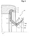
- FIG. 2 to 4 show the seals 1b to 1d, their structure largely coincides with the seal 1 a according to FIG. 1.
- Matching Components are therefore provided with the same reference numbers. The following Descriptions therefore refer in particular to the differences from Seal 1 a.
- the seal 1b shown in Figure 2 includes the axial sealing lip 11b, the Forms sections 15b, 16b. At the first section 15b, which is in the angle of attack " ⁇ " runs to the axis of symmetry 5, closes an angled one Section 16b, which is at an angle of inclination “ ⁇ ” to the axis of symmetry 5 is inclined. A bending joint is formed between the sections 15b, 16b 17b.
- the flexible joint 17b has on the inside, on the axial sealing lip 11b a circumferential groove 18b, whereby a deliberate Material thinning of the sealing lip 11 b sets, which in the installed state the elasticity of the sealing lip 11 b in particular that of the angled section 16b improved.
- the seal 1b is designed with an alternative to that in FIG Sealing lip 11 e shown.
- the flexure 17e does not include a fillet, all of them other characteristics are the same.
- the axial sealing lip 11c of the seal 1c comprises the sections 15c, 16c between which the flexible joint 17c is provided.
- the flexible joint 17c has a circumferential groove 18c arranged on the outside of the sealing lip 11c.
- the flexible joint 17c is preferably arranged such that the flexible joint 17c is at a distance "Z 1 " from the sealing edge 8 of the radial sealing lip in the non-installed, stress-free state of the seal 1c, the distance "Z 1 " ⁇ 0.5 Distance "Z” corresponds, which indicates the axial distance between the sealing edge 8 and the end face 13 of the axial sealing lip 11c.
- FIG. 3 contains further information on the design of the seal 1c.
- the inside diameter is advantageously "d” ⁇ 16 mm in the de-energized state of the seal 1c.
- the diameter dimension “d s ", which defines the inner diameter of the tube spring 9, is ⁇ 17 mm.
- the dimension “B” determining the seal width is Dicht 3.2 mm.
- a protrusion dimension "b 1 " ⁇ 0.15 mm defines the axial distance between the reinforcement 6 and the bead 2.
- FIG. 4 shows the seal 1d, the axial sealing lip 11d of which is an end section 16d, which has a pitch angle "Y" from the axis of symmetry 5 is turned away.
- the flexure 11 d of the axial sealing lip 11 d is thereby by a circumferential provided on the outside of the sealing lip 11 d Groove 18d formed.
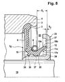
- FIG. 5 shows the seal 1a in the installed state, for sealing a Annular gap, which is between the bearing ring 4 and a rotating Shaft 19, in particular a rotating pump shaft of a water pump, established.
- the seal 1a separates two pressure chambers, one for receiving the rolling elements 21 determined oil space 20 and a water space 22, the Cooling medium, in particular cooling water of an internal combustion engine is.
- the sealing lips of the seal 1 a are assigned to a centrifugal sleeve 23, which is positioned on the shaft 19 and rotates with this component.
- the sealing edge 8 of the radial sealing lip 7 is non-positively supported by the tubular spring 9 on the outer surface 24 of a cylindrical Section 25 of the centrifugal sleeve 23.
- the associated additional axial sealing lip 11a of the seal 1a is supported on a radial axis perpendicular to the axis of symmetry 5 aligned section 26 of the centrifugal sleeve 23.
- a defined installation position characterized by the dimension "X 1 ", is provided between the bearing ring 4 and the centrifugal sleeve 23.
- the determination of the axial overlap "X 2 " in connection with the constructive measures, which relate in particular to the axial sealing lip 11a, enables the sealing lip 11a to optimally bear against the centrifugal sleeve 23.
- the contact surface is at least partially structured in the area of the sealing lip support.
- a waffle 28 is suitable, for example, which has elevations protruding axially from the contact surface 27, which alternatively can also be introduced axially into the contact surface 27.
- the resulting reduced contact area between the axial sealing lip 11a and the contact surface 27 reduces the friction and further enables the inclusion of lubricant or a lubricant that builds up an oil film or a lubricant film between the contact surface 27 and the sealing edge 12 of the axial sealing lip 11a is required.
- the seal 1 a and Centrifugal sleeve 23 is preferably provided for a sequential installation which first the seal 1 a is inserted into the groove 3 before the centrifuge sleeve 23 is fed axially.
- the radial sealing lip 7 is the cylindrical portion 25 of the Centrifugal sleeve 23 is provided with an insertion bevel 31.
- the under the " ⁇ " Angular insertion bevel 31 is selected so that it is during assembly the radial sealing lip 7 spreads so that it is non-destructive to the Shell surface 24 can move.
- the lead-in chamfer 31 offers it is the cylindrical section 25 of the centrifugal sleeve 23 on the end face to be provided with an inner radius 32 which allows the installation of the centrifuge sleeve 23 simplified to the shaft 19.
- the seal 1e according to Figure 6 is also shown in the installed state.
- the seal 1e is provided with two radial sealing lips 34, 35, which are supported axially spaced apart by sealing edges 36, 37 directly on the lateral surface 39 of the shaft 19.
- a radially preloaded, slotted snap ring 39 which is inserted into an annular groove in the seal 1 e, serves to increase the supporting force.
- the axial sealing lip 40 is supported on the contact surface 42 of a centrifugal disc 43 via the sealing edge 41.
- the centrifugal disc 43 is positioned on the shaft 19 such that a defined axial overlap "X 2 " between the sealing edge 41 of the axial sealing lip 40 and the contact surface 42 is established by the centrifugal disc 43 at a distance "X 1 " to the bearing ring 4 is positioned on the shaft 19.
Landscapes
- Engineering & Computer Science (AREA)
- General Engineering & Computer Science (AREA)
- Mechanical Engineering (AREA)
- Sealing With Elastic Sealing Lips (AREA)
- Sealing Of Bearings (AREA)
- Glass Compositions (AREA)
- Sealing Devices (AREA)
Applications Claiming Priority (2)
| Application Number | Priority Date | Filing Date | Title |
|---|---|---|---|
| DE10246398A DE10246398A1 (de) | 2002-10-04 | 2002-10-04 | Wellenlippendichtung |
| DE10246398 | 2002-10-04 |
Publications (3)
| Publication Number | Publication Date |
|---|---|
| EP1406025A2 true EP1406025A2 (fr) | 2004-04-07 |
| EP1406025A3 EP1406025A3 (fr) | 2005-08-24 |
| EP1406025B1 EP1406025B1 (fr) | 2007-01-03 |
Family
ID=31984393
Family Applications (1)
| Application Number | Title | Priority Date | Filing Date |
|---|---|---|---|
| EP03021351A Expired - Lifetime EP1406025B1 (fr) | 2002-10-04 | 2003-09-20 | Joint d'étanchéité à lèvres élastiques pour arbre rotatif |
Country Status (5)
| Country | Link |
|---|---|
| US (1) | US7066471B2 (fr) |
| EP (1) | EP1406025B1 (fr) |
| JP (1) | JP4934943B2 (fr) |
| AT (1) | ATE350594T1 (fr) |
| DE (2) | DE10246398A1 (fr) |
Cited By (4)
| Publication number | Priority date | Publication date | Assignee | Title |
|---|---|---|---|---|
| DE102004037754A1 (de) * | 2004-08-04 | 2006-03-16 | Aktiebolaget Skf | Dichtungsanordnung, Fahrradtretlager und Fahrradnabe mit der Dichtungsanordnung |
| EP1972713A1 (fr) * | 2007-03-21 | 2008-09-24 | Aktiebolaget SKF | Ensemble de sceau annulaire pour insertion entre deux éléments relativement rotatifs, en particulier une cuve et un arbre de rotation du tambour d'un lave-linge |
| ITTO20120307A1 (it) * | 2012-04-06 | 2013-10-07 | Skf Ab | Dispositivo anulare di tenuta |
| CN110892181A (zh) * | 2017-07-07 | 2020-03-17 | Nok株式会社 | 密封装置 |
Families Citing this family (31)
| Publication number | Priority date | Publication date | Assignee | Title |
|---|---|---|---|---|
| DE102004045014B4 (de) * | 2004-09-15 | 2007-06-28 | Ab Skf | Tretlager- oder Radnabenlageranordnung |
| DE102004049550B4 (de) * | 2004-10-12 | 2015-05-13 | Schaeffler Technologies AG & Co. KG | Dichtungsanordnung |
| ITTO20040728A1 (it) * | 2004-10-20 | 2005-01-20 | Rft Spa | Dispositivo di tenuta per cuscinetti |
| DE102004056599A1 (de) * | 2004-11-24 | 2006-06-01 | Volkswagen Ag | Anordnung zur Abdichtug von zwei fluidführenden Baugruppen |
| JP2006161917A (ja) * | 2004-12-06 | 2006-06-22 | Koyo Sealing Techno Co Ltd | 密封装置 |
| DE102004061384B3 (de) * | 2004-12-21 | 2006-03-30 | Federal-Mogul Sealing Systems Bretten Gmbh | Wälzlagerabdichtung |
| JP4807210B2 (ja) * | 2005-12-27 | 2011-11-02 | 株式会社デンソー | シール装置およびシール構造 |
| EP1994294B1 (fr) * | 2006-03-20 | 2010-05-05 | Aktiebolaget SKF | Ensemble d'etancheite annulaire, en particulier pour des moyeux de roue |
| DE102006044272A1 (de) * | 2006-09-20 | 2008-04-03 | Schaeffler Kg | Wälzlagerdichtung und Wälzlager |
| JP2008095919A (ja) * | 2006-10-16 | 2008-04-24 | Nok Corp | 密封装置 |
| CN101517286A (zh) * | 2006-10-16 | 2009-08-26 | Nok株式会社 | 密封装置 |
| JP2009115110A (ja) * | 2007-11-01 | 2009-05-28 | Nok Corp | 密封装置 |
| DE102009006955A1 (de) | 2009-01-31 | 2010-08-05 | Schaeffler Technologies Gmbh & Co. Kg | Dichtungselement für ein Lager |
| DE102010062629A1 (de) * | 2009-12-09 | 2011-06-16 | Schaeffler Technologies Gmbh & Co. Kg | Dichtungsanordnung |
| EP2400189B1 (fr) * | 2010-06-25 | 2014-04-02 | Dichtungstechnik G. Bruss GmbH & Co. KG | Joint d'étanchéité d'arbre, utilisation d'un tel joint et son procédé de fabrication |
| DE102010051230A1 (de) * | 2010-11-12 | 2012-05-16 | Schaeffler Technologies Gmbh & Co. Kg | Abgedichtetes Wälzlager |
| WO2012152808A1 (fr) | 2011-05-12 | 2012-11-15 | Aktiebolaget Skf | Joint d'étanchéité à texture |
| JP6271932B2 (ja) * | 2013-10-02 | 2018-01-31 | Nok株式会社 | オイルシール |
| JP6381232B2 (ja) * | 2014-02-28 | 2018-08-29 | 日本精工株式会社 | 転がり軸受 |
| WO2016089764A1 (fr) * | 2014-12-02 | 2016-06-09 | Robert Bosch Gmbh | Protection de joint et lubrifiant dans un outil électrique à entraînement par vis sans fin |
| US20160273656A1 (en) * | 2015-03-19 | 2016-09-22 | GM Global Technology Operations LLC | Shaft seal system |
| CN106801745A (zh) * | 2015-11-25 | 2017-06-06 | 舍弗勒技术股份两合公司 | 轴承及用于轴承的密封结构 |
| JPWO2019004141A1 (ja) * | 2017-06-29 | 2020-04-30 | Nok株式会社 | 密封装置 |
| JP6947557B2 (ja) * | 2017-07-07 | 2021-10-13 | Nok株式会社 | 密封装置 |
| DE102017121542A1 (de) * | 2017-09-18 | 2019-03-21 | Schaeffler Technologies AG & Co. KG | Dichtungsanordnung eines Radlagers |
| EP3779246B1 (fr) * | 2018-04-06 | 2025-05-14 | NOK Corporation | Dispositif d'étanchéité |
| DE102019103400A1 (de) * | 2019-02-12 | 2020-08-13 | Schaeffler Technologies AG & Co. KG | Optikmodul mit einer Lagereinrichtung für eine Detektionsvorrichtung sowie Detektionsvorrichtung mit dem Optikmodul |
| DE102020103261A1 (de) | 2020-02-10 | 2021-08-12 | Schaeffler Technologies AG & Co. KG | Axialwälzlager |
| CN111998001A (zh) * | 2020-07-13 | 2020-11-27 | 人本股份有限公司 | 轴连轴承密封组件 |
| EP3991918A1 (fr) * | 2020-10-28 | 2022-05-04 | Hilti Aktiengesellschaft | Géométrie d'étanchéité pour une machine-outil mobile |
| CN115823256A (zh) * | 2021-09-16 | 2023-03-21 | 舍弗勒技术股份两合公司 | 密封装置及其制造方法 |
Family Cites Families (21)
| Publication number | Priority date | Publication date | Assignee | Title |
|---|---|---|---|---|
| US3099454A (en) * | 1961-05-05 | 1963-07-30 | Victor Mfg & Gasket Co | Fluid seal |
| US3929340A (en) * | 1972-04-24 | 1975-12-30 | Chicago Rawhide Mfg Co | Seal with pumping action |
| US3822890A (en) * | 1973-01-15 | 1974-07-09 | Roulements Soc Nouvelle | Bearing seals |
| AT340216B (de) * | 1973-06-22 | 1977-12-12 | Burgmann Dichtungswerk Feodor | Dichtungsanordnung |
| EP0020364B1 (fr) * | 1978-12-26 | 1983-02-23 | Towmotor Corporation | Joint d'etancheite |
| US4527673A (en) * | 1982-09-16 | 1985-07-09 | Chicago Rawhide Manufacturing Company | Multi-purpose fluid seal for movement control dampers and the like |
| JPS6064367A (ja) * | 1983-09-19 | 1985-04-12 | Konishiroku Photo Ind Co Ltd | 画像記録装置 |
| US4699526A (en) * | 1985-08-01 | 1987-10-13 | Nok Corporation | Sealing device for bearings |
| IT1211622B (it) * | 1987-12-23 | 1989-11-03 | Riv Officine Di Villar Perosa | Schermo di tenuta in particolareper un cuscinetto di rotolamento avente un dispositivo di ancoraggio di tipo perfezionato |
| JPH03105769A (ja) * | 1989-09-20 | 1991-05-02 | Matsushita Electric Ind Co Ltd | 情報再生装置 |
| JPH0422653A (ja) * | 1990-05-18 | 1992-01-27 | Canon Inc | 印字装置 |
| JPH0979274A (ja) * | 1995-09-11 | 1997-03-25 | Koyo Seiko Co Ltd | オイルシ−ル装置 |
| JPH09287619A (ja) * | 1996-02-23 | 1997-11-04 | Nippon Seiko Kk | 密封装置付転がり軸受ユニット |
| DE19614649A1 (de) * | 1996-04-13 | 1997-10-16 | Fag Automobiltechnik Ag | Dichtung, insbesondere Wälzlagerdichtung |
| IT239743Y1 (it) * | 1996-05-17 | 2001-03-13 | Skf Ind Spa | Sistema di tenuta per organi meccnici accoppiati in rotazionerelativa. |
| IT1291208B1 (it) * | 1997-03-18 | 1998-12-29 | Skf Ind Spa | Complesso di tenuta multicontatto per organi meccanici accoppiati in rotazione relativa. |
| IT1303234B1 (it) * | 1998-08-18 | 2000-11-02 | Rft Spa | Complesso di tenuta, in particolare per alberi motore di veicoli. |
| ITMI20010963A1 (it) * | 2001-05-10 | 2002-11-10 | Rft Spa | Complesso di tenuta per organi meccanici relativamente rotanti |
| JP2003148628A (ja) * | 2001-11-09 | 2003-05-21 | Nsk Ltd | ゴムシール装置 |
| US7145904B2 (en) * | 2002-01-03 | 2006-12-05 | Integrated Device Technology, Inc. | Switch queue predictive protocol (SQPP) based packet switching technique |
| US6746018B2 (en) * | 2002-02-21 | 2004-06-08 | Emerson Power Transmission Manufacturing, L.P. | Shaft seal |
-
2002
- 2002-10-04 DE DE10246398A patent/DE10246398A1/de not_active Withdrawn
-
2003
- 2003-09-20 AT AT03021351T patent/ATE350594T1/de not_active IP Right Cessation
- 2003-09-20 EP EP03021351A patent/EP1406025B1/fr not_active Expired - Lifetime
- 2003-09-20 DE DE50306168T patent/DE50306168D1/de not_active Expired - Lifetime
- 2003-10-02 US US10/677,637 patent/US7066471B2/en not_active Expired - Lifetime
- 2003-10-06 JP JP2003347478A patent/JP4934943B2/ja not_active Expired - Fee Related
Cited By (6)
| Publication number | Priority date | Publication date | Assignee | Title |
|---|---|---|---|---|
| DE102004037754A1 (de) * | 2004-08-04 | 2006-03-16 | Aktiebolaget Skf | Dichtungsanordnung, Fahrradtretlager und Fahrradnabe mit der Dichtungsanordnung |
| EP1972713A1 (fr) * | 2007-03-21 | 2008-09-24 | Aktiebolaget SKF | Ensemble de sceau annulaire pour insertion entre deux éléments relativement rotatifs, en particulier une cuve et un arbre de rotation du tambour d'un lave-linge |
| US7926814B2 (en) | 2007-03-21 | 2011-04-19 | Aktiebolaget Skf | Annular seal assembly for insertion between two relatively rotatable members and method for its use |
| ITTO20120307A1 (it) * | 2012-04-06 | 2013-10-07 | Skf Ab | Dispositivo anulare di tenuta |
| EP2647752A1 (fr) * | 2012-04-06 | 2013-10-09 | Aktiebolaget SKF | Dispositif d'étanchéité annulaire |
| CN110892181A (zh) * | 2017-07-07 | 2020-03-17 | Nok株式会社 | 密封装置 |
Also Published As
| Publication number | Publication date |
|---|---|
| JP4934943B2 (ja) | 2012-05-23 |
| US20040113366A1 (en) | 2004-06-17 |
| DE10246398A1 (de) | 2004-04-29 |
| ATE350594T1 (de) | 2007-01-15 |
| JP2004125176A (ja) | 2004-04-22 |
| EP1406025B1 (fr) | 2007-01-03 |
| US7066471B2 (en) | 2006-06-27 |
| EP1406025A3 (fr) | 2005-08-24 |
| DE50306168D1 (de) | 2007-02-15 |
Similar Documents
| Publication | Publication Date | Title |
|---|---|---|
| EP1406025A2 (fr) | Joint d'étanchéité à lèvres élastiques pour arbre rotatif | |
| DE3874538T2 (de) | Radialwellendichtungsring mit rippen, die ein mitdrehen verhindern. | |
| EP1585905B1 (fr) | Module d'etancheite pour un coussinet | |
| DE4412132C5 (de) | Abdichtung für eine Gelenkkreuzbüchse | |
| EP0213543A2 (fr) | Palier à cage divisée pour barres stabilisatrices ou similaires dans des véhicules automoteurs | |
| EP2817539B1 (fr) | Joint radial d'arbre | |
| WO2008138698A1 (fr) | Unité de construction radiale avec roulement à aiguilles | |
| EP3458746B1 (fr) | Ensemble à joint d'étanchéité rotatif comprenant un joint d'étanchéité rotatif pouvant être activé par la pression et joint d'étanchéité rotatif | |
| DE102011078840A1 (de) | Pendelrollenlager mit Dichtungsanordnung sowie Flossenstabilisator mit dem Pendelrollenlager | |
| DE102018006945B3 (de) | Radialwellendichtung | |
| EP0091983B1 (fr) | Cartouche d'étanchéité | |
| EP0289498A1 (fr) | Joints d'etancheite aux liquides pour elements de machines effectuant des mouvements relatifs rotatifs et axiaux | |
| DE19925895A1 (de) | Kreuzgelenk für eine Kardangelenkanordnung | |
| EP2561255B1 (fr) | Bague collectrice d'étanchéité | |
| DE102012207745A1 (de) | Pendelrollenlager mit Dichtscheibe | |
| DE4018796C2 (fr) | ||
| DE3920482C2 (fr) | ||
| EP4226061B1 (fr) | Agencement d'étanchéité pour roulements de roue et ensemble roulement de roue doté d'agencement d'étanchéité | |
| DE19510761A1 (de) | Anlaufscheibe für Gelenkkreuzbüchsen | |
| DE102006031774A1 (de) | Torsionsschwingungsdämpfer, insbesondere Zweimassenschwungrad zwischen der Brennkraftmaschine und dem Getriebe eines Kraftfahrzeuges | |
| DE10062983A1 (de) | Abdichtung für ein Lagerauge | |
| DE2723041B2 (de) | Dichtung | |
| DE10252433A1 (de) | Abdichtung für eine Lagerbüchse | |
| DE3336863A1 (de) | Radialwellendichtring | |
| DE102005012239B4 (de) | Gelenklageranordnung |
Legal Events
| Date | Code | Title | Description |
|---|---|---|---|
| PUAI | Public reference made under article 153(3) epc to a published international application that has entered the european phase |
Free format text: ORIGINAL CODE: 0009012 |
|
| 17P | Request for examination filed |
Effective date: 20030920 |
|
| AK | Designated contracting states |
Kind code of ref document: A2 Designated state(s): AT BE BG CH CY CZ DE DK EE ES FI FR GB GR HU IE IT LI LU MC NL PT RO SE SI SK TR |
|
| AX | Request for extension of the european patent |
Extension state: AL LT LV MK |
|
| PUAL | Search report despatched |
Free format text: ORIGINAL CODE: 0009013 |
|
| AK | Designated contracting states |
Kind code of ref document: A3 Designated state(s): AT BE BG CH CY CZ DE DK EE ES FI FR GB GR HU IE IT LI LU MC NL PT RO SE SI SK TR |
|
| AX | Request for extension of the european patent |
Extension state: AL LT LV MK |
|
| RAP1 | Party data changed (applicant data changed or rights of an application transferred) |
Owner name: SCHAEFFLER KG |
|
| AKX | Designation fees paid |
Designated state(s): AT BE BG CH CY CZ DE DK EE ES FI FR GB GR HU IE IT LI LU MC NL PT RO SE SI SK TR |
|
| GRAP | Despatch of communication of intention to grant a patent |
Free format text: ORIGINAL CODE: EPIDOSNIGR1 |
|
| GRAS | Grant fee paid |
Free format text: ORIGINAL CODE: EPIDOSNIGR3 |
|
| GRAA | (expected) grant |
Free format text: ORIGINAL CODE: 0009210 |
|
| AK | Designated contracting states |
Kind code of ref document: B1 Designated state(s): AT BE BG CH CY CZ DE DK EE ES FI FR GB GR HU IE IT LI LU MC NL PT RO SE SI SK TR |
|
| PG25 | Lapsed in a contracting state [announced via postgrant information from national office to epo] |
Ref country code: NL Free format text: LAPSE BECAUSE OF FAILURE TO SUBMIT A TRANSLATION OF THE DESCRIPTION OR TO PAY THE FEE WITHIN THE PRESCRIBED TIME-LIMIT Effective date: 20070103 Ref country code: SI Free format text: LAPSE BECAUSE OF FAILURE TO SUBMIT A TRANSLATION OF THE DESCRIPTION OR TO PAY THE FEE WITHIN THE PRESCRIBED TIME-LIMIT Effective date: 20070103 Ref country code: FI Free format text: LAPSE BECAUSE OF FAILURE TO SUBMIT A TRANSLATION OF THE DESCRIPTION OR TO PAY THE FEE WITHIN THE PRESCRIBED TIME-LIMIT Effective date: 20070103 Ref country code: IE Free format text: LAPSE BECAUSE OF FAILURE TO SUBMIT A TRANSLATION OF THE DESCRIPTION OR TO PAY THE FEE WITHIN THE PRESCRIBED TIME-LIMIT Effective date: 20070103 Ref country code: DK Free format text: LAPSE BECAUSE OF FAILURE TO SUBMIT A TRANSLATION OF THE DESCRIPTION OR TO PAY THE FEE WITHIN THE PRESCRIBED TIME-LIMIT Effective date: 20070103 |
|
| REG | Reference to a national code |
Ref country code: GB Ref legal event code: FG4D Free format text: NOT ENGLISH |
|
| REF | Corresponds to: |
Ref document number: 50306168 Country of ref document: DE Date of ref document: 20070215 Kind code of ref document: P |
|
| REG | Reference to a national code |
Ref country code: IE Ref legal event code: FG4D Free format text: LANGUAGE OF EP DOCUMENT: GERMAN |
|
| PG25 | Lapsed in a contracting state [announced via postgrant information from national office to epo] |
Ref country code: BG Free format text: LAPSE BECAUSE OF FAILURE TO SUBMIT A TRANSLATION OF THE DESCRIPTION OR TO PAY THE FEE WITHIN THE PRESCRIBED TIME-LIMIT Effective date: 20070403 Ref country code: SE Free format text: LAPSE BECAUSE OF FAILURE TO SUBMIT A TRANSLATION OF THE DESCRIPTION OR TO PAY THE FEE WITHIN THE PRESCRIBED TIME-LIMIT Effective date: 20070403 |
|
| GBT | Gb: translation of ep patent filed (gb section 77(6)(a)/1977) |
Effective date: 20070308 |
|
| PG25 | Lapsed in a contracting state [announced via postgrant information from national office to epo] |
Ref country code: ES Free format text: LAPSE BECAUSE OF FAILURE TO SUBMIT A TRANSLATION OF THE DESCRIPTION OR TO PAY THE FEE WITHIN THE PRESCRIBED TIME-LIMIT Effective date: 20070414 |
|
| PG25 | Lapsed in a contracting state [announced via postgrant information from national office to epo] |
Ref country code: PT Free format text: LAPSE BECAUSE OF FAILURE TO SUBMIT A TRANSLATION OF THE DESCRIPTION OR TO PAY THE FEE WITHIN THE PRESCRIBED TIME-LIMIT Effective date: 20070604 |
|
| ET | Fr: translation filed | ||
| NLV1 | Nl: lapsed or annulled due to failure to fulfill the requirements of art. 29p and 29m of the patents act | ||
| REG | Reference to a national code |
Ref country code: IE Ref legal event code: FD4D |
|
| PLBE | No opposition filed within time limit |
Free format text: ORIGINAL CODE: 0009261 |
|
| STAA | Information on the status of an ep patent application or granted ep patent |
Free format text: STATUS: NO OPPOSITION FILED WITHIN TIME LIMIT |
|
| PG25 | Lapsed in a contracting state [announced via postgrant information from national office to epo] |
Ref country code: SK Free format text: LAPSE BECAUSE OF FAILURE TO SUBMIT A TRANSLATION OF THE DESCRIPTION OR TO PAY THE FEE WITHIN THE PRESCRIBED TIME-LIMIT Effective date: 20070103 |
|
| 26N | No opposition filed |
Effective date: 20071005 |
|
| PG25 | Lapsed in a contracting state [announced via postgrant information from national office to epo] |
Ref country code: CZ Free format text: LAPSE BECAUSE OF FAILURE TO SUBMIT A TRANSLATION OF THE DESCRIPTION OR TO PAY THE FEE WITHIN THE PRESCRIBED TIME-LIMIT Effective date: 20070103 Ref country code: RO Free format text: LAPSE BECAUSE OF FAILURE TO SUBMIT A TRANSLATION OF THE DESCRIPTION OR TO PAY THE FEE WITHIN THE PRESCRIBED TIME-LIMIT Effective date: 20070103 |
|
| BERE | Be: lapsed |
Owner name: SCHAEFFLER K.G. Effective date: 20070930 |
|
| PG25 | Lapsed in a contracting state [announced via postgrant information from national office to epo] |
Ref country code: GR Free format text: LAPSE BECAUSE OF FAILURE TO SUBMIT A TRANSLATION OF THE DESCRIPTION OR TO PAY THE FEE WITHIN THE PRESCRIBED TIME-LIMIT Effective date: 20070404 Ref country code: MC Free format text: LAPSE BECAUSE OF NON-PAYMENT OF DUE FEES Effective date: 20070930 |
|
| REG | Reference to a national code |
Ref country code: CH Ref legal event code: PL |
|
| PG25 | Lapsed in a contracting state [announced via postgrant information from national office to epo] |
Ref country code: LI Free format text: LAPSE BECAUSE OF NON-PAYMENT OF DUE FEES Effective date: 20070930 Ref country code: CH Free format text: LAPSE BECAUSE OF NON-PAYMENT OF DUE FEES Effective date: 20070930 |
|
| PG25 | Lapsed in a contracting state [announced via postgrant information from national office to epo] |
Ref country code: BE Free format text: LAPSE BECAUSE OF NON-PAYMENT OF DUE FEES Effective date: 20070930 |
|
| PG25 | Lapsed in a contracting state [announced via postgrant information from national office to epo] |
Ref country code: AT Free format text: LAPSE BECAUSE OF NON-PAYMENT OF DUE FEES Effective date: 20070920 |
|
| PG25 | Lapsed in a contracting state [announced via postgrant information from national office to epo] |
Ref country code: EE Free format text: LAPSE BECAUSE OF FAILURE TO SUBMIT A TRANSLATION OF THE DESCRIPTION OR TO PAY THE FEE WITHIN THE PRESCRIBED TIME-LIMIT Effective date: 20070103 |
|
| PG25 | Lapsed in a contracting state [announced via postgrant information from national office to epo] |
Ref country code: CY Free format text: LAPSE BECAUSE OF FAILURE TO SUBMIT A TRANSLATION OF THE DESCRIPTION OR TO PAY THE FEE WITHIN THE PRESCRIBED TIME-LIMIT Effective date: 20070103 |
|
| PG25 | Lapsed in a contracting state [announced via postgrant information from national office to epo] |
Ref country code: LU Free format text: LAPSE BECAUSE OF NON-PAYMENT OF DUE FEES Effective date: 20070920 |
|
| PG25 | Lapsed in a contracting state [announced via postgrant information from national office to epo] |
Ref country code: TR Free format text: LAPSE BECAUSE OF FAILURE TO SUBMIT A TRANSLATION OF THE DESCRIPTION OR TO PAY THE FEE WITHIN THE PRESCRIBED TIME-LIMIT Effective date: 20070103 Ref country code: HU Free format text: LAPSE BECAUSE OF FAILURE TO SUBMIT A TRANSLATION OF THE DESCRIPTION OR TO PAY THE FEE WITHIN THE PRESCRIBED TIME-LIMIT Effective date: 20070704 |
|
| REG | Reference to a national code |
Ref country code: FR Ref legal event code: GC |
|
| REG | Reference to a national code |
Ref country code: GB Ref legal event code: 732E Free format text: REGISTERED BETWEEN 20091224 AND 20091230 |
|
| PGFP | Annual fee paid to national office [announced via postgrant information from national office to epo] |
Ref country code: IT Payment date: 20100930 Year of fee payment: 8 |
|
| PGFP | Annual fee paid to national office [announced via postgrant information from national office to epo] |
Ref country code: GB Payment date: 20110930 Year of fee payment: 9 |
|
| PGFP | Annual fee paid to national office [announced via postgrant information from national office to epo] |
Ref country code: FR Payment date: 20111012 Year of fee payment: 9 |
|
| REG | Reference to a national code |
Ref country code: GB Ref legal event code: 732E Free format text: REGISTERED BETWEEN 20120712 AND 20120718 |
|
| REG | Reference to a national code |
Ref country code: DE Ref legal event code: R081 Ref document number: 50306168 Country of ref document: DE Owner name: SCHAEFFLER TECHNOLOGIES AG & CO. KG, DE Free format text: FORMER OWNER: SCHAEFFLER TECHNOLOGIES GMBH & CO. KG, 91074 HERZOGENAURACH, DE Effective date: 20120828 Ref country code: DE Ref legal event code: R081 Ref document number: 50306168 Country of ref document: DE Owner name: SCHAEFFLER TECHNOLOGIES GMBH & CO. KG, DE Free format text: FORMER OWNER: SCHAEFFLER TECHNOLOGIES GMBH & CO. KG, 91074 HERZOGENAURACH, DE Effective date: 20120828 |
|
| REG | Reference to a national code |
Ref country code: FR Ref legal event code: TP Owner name: SCHAEFFLER TECHNOLOGIES AG & CO. KG, DE Effective date: 20121022 Ref country code: FR Ref legal event code: RG Effective date: 20121022 Ref country code: FR Ref legal event code: CD Owner name: SCHAEFFLER TECHNOLOGIES AG & CO. KG, DE Effective date: 20121022 Ref country code: FR Ref legal event code: CJ Effective date: 20121022 |
|
| GBPC | Gb: european patent ceased through non-payment of renewal fee |
Effective date: 20120920 |
|
| REG | Reference to a national code |
Ref country code: FR Ref legal event code: ST Effective date: 20130531 |
|
| PG25 | Lapsed in a contracting state [announced via postgrant information from national office to epo] |
Ref country code: GB Free format text: LAPSE BECAUSE OF NON-PAYMENT OF DUE FEES Effective date: 20120920 |
|
| PG25 | Lapsed in a contracting state [announced via postgrant information from national office to epo] |
Ref country code: IT Free format text: LAPSE BECAUSE OF NON-PAYMENT OF DUE FEES Effective date: 20120920 Ref country code: FR Free format text: LAPSE BECAUSE OF NON-PAYMENT OF DUE FEES Effective date: 20121001 |
|
| REG | Reference to a national code |
Ref country code: DE Ref legal event code: R081 Ref document number: 50306168 Country of ref document: DE Owner name: SCHAEFFLER TECHNOLOGIES GMBH & CO. KG, DE Free format text: FORMER OWNER: SCHAEFFLER TECHNOLOGIES AG & CO. KG, 91074 HERZOGENAURACH, DE Effective date: 20140213 Ref country code: DE Ref legal event code: R081 Ref document number: 50306168 Country of ref document: DE Owner name: SCHAEFFLER TECHNOLOGIES AG & CO. KG, DE Free format text: FORMER OWNER: SCHAEFFLER TECHNOLOGIES AG & CO. KG, 91074 HERZOGENAURACH, DE Effective date: 20140213 |
|
| PGFP | Annual fee paid to national office [announced via postgrant information from national office to epo] |
Ref country code: DE Payment date: 20141128 Year of fee payment: 12 |
|
| REG | Reference to a national code |
Ref country code: DE Ref legal event code: R081 Ref document number: 50306168 Country of ref document: DE Owner name: SCHAEFFLER TECHNOLOGIES AG & CO. KG, DE Free format text: FORMER OWNER: SCHAEFFLER TECHNOLOGIES GMBH & CO. KG, 91074 HERZOGENAURACH, DE Effective date: 20150127 |
|
| REG | Reference to a national code |
Ref country code: DE Ref legal event code: R119 Ref document number: 50306168 Country of ref document: DE |
|
| PG25 | Lapsed in a contracting state [announced via postgrant information from national office to epo] |
Ref country code: DE Free format text: LAPSE BECAUSE OF NON-PAYMENT OF DUE FEES Effective date: 20160401 |
|
| P01 | Opt-out of the competence of the unified patent court (upc) registered |
Effective date: 20230522 |