EP1406110A1 - Strahlteilender oder polarisierender Kubus und Herstellungsverfahren - Google Patents
Strahlteilender oder polarisierender Kubus und Herstellungsverfahren Download PDFInfo
- Publication number
- EP1406110A1 EP1406110A1 EP20030022272 EP03022272A EP1406110A1 EP 1406110 A1 EP1406110 A1 EP 1406110A1 EP 20030022272 EP20030022272 EP 20030022272 EP 03022272 A EP03022272 A EP 03022272A EP 1406110 A1 EP1406110 A1 EP 1406110A1
- Authority
- EP
- European Patent Office
- Prior art keywords
- prism
- coating
- cube
- contact layer
- uncoated
- Prior art date
- Legal status (The legal status is an assumption and is not a legal conclusion. Google has not performed a legal analysis and makes no representation as to the accuracy of the status listed.)
- Granted
Links
- 238000004519 manufacturing process Methods 0.000 title claims description 5
- VYPSYNLAJGMNEJ-UHFFFAOYSA-N Silicium dioxide Chemical group O=[Si]=O VYPSYNLAJGMNEJ-UHFFFAOYSA-N 0.000 claims abstract description 31
- 230000003287 optical effect Effects 0.000 claims abstract description 24
- 239000000377 silicon dioxide Substances 0.000 claims abstract description 11
- 239000005350 fused silica glass Substances 0.000 claims abstract description 9
- 229910052681 coesite Inorganic materials 0.000 claims abstract 4
- 229910052906 cristobalite Inorganic materials 0.000 claims abstract 4
- 229910052682 stishovite Inorganic materials 0.000 claims abstract 4
- 229910052905 tridymite Inorganic materials 0.000 claims abstract 4
- 238000000576 coating method Methods 0.000 claims description 47
- 238000000034 method Methods 0.000 claims description 44
- 239000011248 coating agent Substances 0.000 claims description 32
- 230000008878 coupling Effects 0.000 claims description 4
- 238000010168 coupling process Methods 0.000 claims description 4
- 238000005859 coupling reaction Methods 0.000 claims description 4
- 238000005566 electron beam evaporation Methods 0.000 claims description 4
- 230000008020 evaporation Effects 0.000 claims description 4
- 238000001704 evaporation Methods 0.000 claims description 4
- 239000011521 glass Substances 0.000 claims description 3
- 238000001659 ion-beam spectroscopy Methods 0.000 claims description 3
- 238000001755 magnetron sputter deposition Methods 0.000 claims description 2
- 238000004544 sputter deposition Methods 0.000 claims 3
- 239000000463 material Substances 0.000 abstract description 16
- WUKWITHWXAAZEY-UHFFFAOYSA-L calcium difluoride Chemical compound [F-].[F-].[Ca+2] WUKWITHWXAAZEY-UHFFFAOYSA-L 0.000 abstract description 4
- 229910001634 calcium fluoride Inorganic materials 0.000 abstract description 3
- 239000010410 layer Substances 0.000 abstract 3
- 239000011247 coating layer Substances 0.000 abstract 1
- 238000000151 deposition Methods 0.000 description 6
- 230000008021 deposition Effects 0.000 description 3
- 238000005137 deposition process Methods 0.000 description 2
- 238000010894 electron beam technology Methods 0.000 description 2
- 238000001459 lithography Methods 0.000 description 2
- ORUIBWPALBXDOA-UHFFFAOYSA-L magnesium fluoride Chemical compound [F-].[F-].[Mg+2] ORUIBWPALBXDOA-UHFFFAOYSA-L 0.000 description 2
- 229910001635 magnesium fluoride Inorganic materials 0.000 description 2
- 239000002994 raw material Substances 0.000 description 2
- 235000012239 silicon dioxide Nutrition 0.000 description 2
- XRADHEAKQRNYQQ-UHFFFAOYSA-K trifluoroneodymium Chemical compound F[Nd](F)F XRADHEAKQRNYQQ-UHFFFAOYSA-K 0.000 description 2
- KLZUFWVZNOTSEM-UHFFFAOYSA-K Aluminium flouride Chemical compound F[Al](F)F KLZUFWVZNOTSEM-UHFFFAOYSA-K 0.000 description 1
- KRHYYFGTRYWZRS-UHFFFAOYSA-M Fluoride anion Chemical compound [F-] KRHYYFGTRYWZRS-UHFFFAOYSA-M 0.000 description 1
- 238000010521 absorption reaction Methods 0.000 description 1
- 150000001875 compounds Chemical class 0.000 description 1
- 230000007613 environmental effect Effects 0.000 description 1
- 239000000203 mixture Substances 0.000 description 1
- 230000010287 polarization Effects 0.000 description 1
- 238000002310 reflectometry Methods 0.000 description 1
- 239000000758 substrate Substances 0.000 description 1
- TYIZUJNEZNBXRS-UHFFFAOYSA-K trifluorogadolinium Chemical compound F[Gd](F)F TYIZUJNEZNBXRS-UHFFFAOYSA-K 0.000 description 1
Images


Classifications
-
- C—CHEMISTRY; METALLURGY
- C03—GLASS; MINERAL OR SLAG WOOL
- C03C—CHEMICAL COMPOSITION OF GLASSES, GLAZES OR VITREOUS ENAMELS; SURFACE TREATMENT OF GLASS; SURFACE TREATMENT OF FIBRES OR FILAMENTS MADE FROM GLASS, MINERALS OR SLAGS; JOINING GLASS TO GLASS OR OTHER MATERIALS
- C03C27/00—Joining pieces of glass to pieces of other inorganic material; Joining glass to glass other than by fusing
-
- G—PHYSICS
- G02—OPTICS
- G02B—OPTICAL ELEMENTS, SYSTEMS OR APPARATUS
- G02B27/00—Optical systems or apparatus not provided for by any of the groups G02B1/00 - G02B26/00, G02B30/00
- G02B27/10—Beam splitting or combining systems
- G02B27/14—Beam splitting or combining systems operating by reflection only
- G02B27/142—Coating structures, e.g. thin films multilayers
-
- G—PHYSICS
- G02—OPTICS
- G02B—OPTICAL ELEMENTS, SYSTEMS OR APPARATUS
- G02B27/00—Optical systems or apparatus not provided for by any of the groups G02B1/00 - G02B26/00, G02B30/00
- G02B27/28—Optical systems or apparatus not provided for by any of the groups G02B1/00 - G02B26/00, G02B30/00 for polarising
- G02B27/283—Optical systems or apparatus not provided for by any of the groups G02B1/00 - G02B26/00, G02B30/00 for polarising used for beam splitting or combining
Definitions
- the present invention relates to a cube and method of making same.
- a prism with a coating e.g., a dielectric stack
- a coating e.g., a dielectric stack
- Many parameters must be taken into consideration when optically contacting the prisms to ensure they remain bonded and that they have a certain amount of optical compatibility. Being compatible ensures the lowest amount of reflection occurs when light travels between the bonded surfaces. Problems with adherence and reflection are more common with cubes manufactured for systems using shorter wavelengths of light (e.g., vacuum ultra violet (VUV) and deep ultra violet (DUV) light).
- VUV vacuum ultra violet
- DUV deep ultra violet
- An embodiment of the present invention provides a method of making a cube.
- the method includes the steps of performing a multi-layer coating process to form a multi-layer coating on a prism, performing a contact layer coating process to form a contact layer coating on top of the multi-layer coating, and coupling the prism to an uncoated prism.
- the contacting layer coating process includes the step of forming a silicon dioxide (SiO 2 ) or fused silica layer as the contact layer.
- Another embodiment of the present invention provides a cube including an uncoated prism and a coated prism coupled to the uncoated prism.
- the coated prism includes a first coating section having a multi-layered coating and a second coating section formed on top of the first coating section.
- the second coating section has a contact layer coating, which can be a SiO 2 or fused silica coating.
- An advantage of the cube made by the process according to embodiments of the present invention is that it allows for secure bonding between an uncoated and coated prism though use of the contact layer, while still providing high throughput and low reflection between bonded surfaces.
- FIG. 1 shows an exemplary environment in which a cube according to embodiments of the present invention is used.
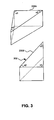
- FIG. 2 shows a perspective view of an exemplary cube formed by two prisms according to embodiments of the present invention.
- FIGS. 3 is an exploded view showing the two prisms used to form the cube of FIG. 2.
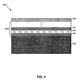
- FIG. 4 is a cross-section of a portion of one of the two prisms in FIGS. 2-3.
- FIG. 5 shows an exemplary vacuum chamber used during part of a process that forms a cube according to embodiments of the present invention.
- FIG. 6 shows a flow chart depicting method steps for a process used to form a cube according to embodiments of the present invention.
- FIG. 7 shows a more detailed flow chart depicting method steps used during the process of FIG. 6.
- Embodiments of the present invention provide a cube used to perform optical functions in a system, such as beam splitting or polarizing, or both, that is manufactured by optically contacting a coated prism with an uncoated prism.
- the coated prism includes a dielectric stack having alternating layers of high and low index of refraction materials.
- a contacting layer is deposited on the dielectric stack.
- the contacting layer can be fused silica or silicon dioxide (SiO 2 ), which have natural compatibility with the calcium fluoride (CaF 2 ) materials that make up the uncoated prism.
- FIG. 1 A system 100 utilizing a cube 102 manufactured according to embodiments of the present invention is shown in FIG. 1.
- the system 100 includes a laser 104 that emits light through a beam conditioner 106, a reticle 108, and projection optics 110. After passing through the projection optics 110, the light is reflected by a portion of the cube 102 towards a reflector 112.
- the reflector 112 reflects the light back through the cube 102 and through wafer group optics 114 onto a wafer 116 to write a pattern on the wafer 116.
- any system requiring the cube 102 to perform various optical functions falls within the scope of the embodiments of the present invention.
- the cube 102 is formed by coupling a coated optical element 200A to an uncoated optical element 200B according to an embodiment of the present invention.
- a surface 300 of prism 200A and a surface 302 of prism 200B are coupled together during an optical contacting process, which is discussed in more detail below.
- optical element 200A can be uncoated and optical element 200B can be coated.
- the optical elements 200 are prisms made from CaF 2 with similar dimensions, although other embodiments utilize prisms 200 of different dimensions and compositions.
- one of the prisms 200A has a dielectric stack 400 deposited onto a main body 402 of the prism 200A.
- the dielectric stack 400 includes multiple and alternating layers of high 404 and low 406 index of refraction materials. These layers 404 and 406 are deposited onto the main body 402 of the prism 200 during a multi-layer coating process 604, discussed in more detail below.
- the dielectric stack 400 can contain a plurality (e.g., 20-50) of layers having with each layer being 500 mm - 2 micron thick, depending on the environment in which the cube 102 is used.
- the high index of refraction material is gadolinium fluoride (GdF 3 ) or lanthium fluoride (LaF 3 ) and the low index of refraction material is magnesium fluoride (MgF 3 ).
- the high index of refraction material is neodymium fluoride (NdF 3 ) and the low index of refraction material is aluminum fluoride (AlF 3 ).
- other materials with the same properties as those described above can be used.
- a contact layer 408 is deposited on top of the dielectric stack 400 during a contact layer depositing process 606, discussed in more detail below.
- the contact layer 408 can be a fused silica or SiO 2 layer.
- the contact layer 408 is a naturally compatible material with the CaF 2 material of the uncoated prism 200B. This allows for secure glass-to-glass bonding between the two prisms 200, while ensuring there is little to no interface reflection.
- the vacuum chamber 500 includes a coating nest 502 that holds the prism 200 during deposition operations.
- a sputter device 504 e.g., sputter gun
- a electron beam device 506 e.g., electron beam gun
- other deposition devices can be used to form the cube 102.
- FIG. 6 shows a method 600 for forming the cube 102 according to embodiments of the present invention.
- the prisms 200A-B which are received from a manufacturer in raw material form, are processed.
- a multi-layer coating process is performed to build the dielectric stack 400 on the main body 402 of the coated prism 200A.
- a contact layer coating process is performed that deposits a contact layer 408 on the dielectric stack 400.
- an optical contacting process is performed that couples the coated prism 200A to the uncoated prism 200B.
- the method 600 ends at step 610.
- FIG. 7 shows more detailed method steps for method 600 according to embodiments of the present invention.
- the prisms 200A-B are receive in as raw material at step 700.
- the prisms 200A-B are polished until they conform to end-user specified parameters (e.g., wavelength, dimensions, etc.).
- the prisms 200A-B are cleaned at step 704 and inspected at step 706 to ensure they meet the end-user specifications.
- the prism 200A that will become a coated prism is placed in the vacuum chamber 500 at step 708.
- a multi-layer coating process is performed at step 710.
- alternating deposition of a layer of high index of refraction material 404 and a layer of low index of refraction material 406 forms the dielectric stack 400.
- the deposition process can be performed by electron beam evaporation, ion beam sputtering, resistance source evaporation, or any other known deposition method.
- the coated prism 200A is cooled at step 721 and inspected at step 714.
- the coated prism 200A is again placed in the vacuum chamber 500 at step 716.
- a contacting layer 408 e.g., a fused silica or SiO 2 layer
- the specific process used to deposit the contacting layer 408 is chosen based on the end use of the cube 102. In embodiments when an end-user's system will be using light in the 157 nm range, the contact layer 408 is deposited with a magnetron sputtering process or an ion beam sputtering process.
- the coated prism 200A is cooled at step 720 and inspected at step 722.
- coated prism 200A can remain in vacuum chamber 500 after multi-layer coating process 604.
- contact layer forming process 606 can be immediately performed without any intervening steps.
- the prisms 200A-B are prepared (e.g., cleaned and positioned) at step 724.
- the prisms 200A-B are optically contacted to securely bond surfaces 300 and 302 together. In some embodiments this is accomplished through glass-to-glass bonding. In other embodiments, other bonding techniques can be used.
Landscapes
- Physics & Mathematics (AREA)
- General Physics & Mathematics (AREA)
- Optics & Photonics (AREA)
- Chemical & Material Sciences (AREA)
- Engineering & Computer Science (AREA)
- General Chemical & Material Sciences (AREA)
- Life Sciences & Earth Sciences (AREA)
- Chemical Kinetics & Catalysis (AREA)
- Ceramic Engineering (AREA)
- Geochemistry & Mineralogy (AREA)
- Materials Engineering (AREA)
- Organic Chemistry (AREA)
- Optical Elements Other Than Lenses (AREA)
- Polarising Elements (AREA)
- Optical Filters (AREA)
- Surface Treatment Of Optical Elements (AREA)
- Physical Vapour Deposition (AREA)
Applications Claiming Priority (2)
| Application Number | Priority Date | Filing Date | Title |
|---|---|---|---|
| US260308 | 2002-10-01 | ||
| US10/260,308 US6824654B2 (en) | 2002-10-01 | 2002-10-01 | Method of making a cube |
Publications (2)
| Publication Number | Publication Date |
|---|---|
| EP1406110A1 true EP1406110A1 (de) | 2004-04-07 |
| EP1406110B1 EP1406110B1 (de) | 2010-12-29 |
Family
ID=31993528
Family Applications (1)
| Application Number | Title | Priority Date | Filing Date |
|---|---|---|---|
| EP03022272A Expired - Lifetime EP1406110B1 (de) | 2002-10-01 | 2003-10-01 | Strahlteilender oder polarisierender Kubus und Herstellungsverfahren |
Country Status (8)
| Country | Link |
|---|---|
| US (2) | US6824654B2 (de) |
| EP (1) | EP1406110B1 (de) |
| JP (1) | JP2004126585A (de) |
| KR (1) | KR100609794B1 (de) |
| CN (1) | CN1329751C (de) |
| DE (1) | DE60335511D1 (de) |
| SG (1) | SG105589A1 (de) |
| TW (1) | TWI278663B (de) |
Cited By (5)
| Publication number | Priority date | Publication date | Assignee | Title |
|---|---|---|---|---|
| EP1705512A1 (de) * | 2005-03-22 | 2006-09-27 | Seiko Epson Corporation | Optisches Produkt und Herstellungsverfahren dafür |
| WO2007075516A3 (en) * | 2005-12-19 | 2007-08-30 | Eastman Kodak Co | Method of making a polarizer plate |
| US7593004B2 (en) | 2005-06-02 | 2009-09-22 | Eastman Kodak Company | Touchscreen with conductive layer comprising carbon nanotubes |
| US8867130B1 (en) | 2010-07-22 | 2014-10-21 | Vuv Analytics, Inc. | Polarization device for vacuum ultraviolet or shorter wavelengths |
| US10338040B2 (en) | 2012-10-18 | 2019-07-02 | Vuv Analytics, Inc. | Vacuum ultraviolet absorption spectroscopy system and method |
Families Citing this family (6)
| Publication number | Priority date | Publication date | Assignee | Title |
|---|---|---|---|---|
| CN100406920C (zh) * | 2005-03-22 | 2008-07-30 | 精工爱普生株式会社 | 光学制品及光学制品的制造方法 |
| CN102116917B (zh) * | 2011-01-19 | 2012-06-27 | 四川欧瑞特光电科技有限公司 | 一种光学元件的光胶方法及其在角锥阵列中实施的方法 |
| CN105676408B (zh) * | 2016-03-14 | 2018-03-02 | 中国科学院西安光学精密机械研究所 | 用于棱镜胶合的支撑结构及胶合工艺 |
| US10677767B2 (en) | 2018-06-12 | 2020-06-09 | Vuv Analytics, Inc. | Vacuum ultraviolet absorption spectroscopy system and method |
| EP4112161A1 (de) | 2020-02-27 | 2023-01-04 | Unitika Ltd. | Filter zur wasserreinigung |
| US12535408B2 (en) | 2024-04-16 | 2026-01-27 | Vuv Analytics, Inc. | Spectroscopy systems and methods for analyzing liquids at vacuum ultraviolet (VUV) wavelengths |
Citations (5)
| Publication number | Priority date | Publication date | Assignee | Title |
|---|---|---|---|---|
| DE1203978B (de) * | 1962-03-23 | 1965-10-28 | Zeiss Carl Fa | Spektralpolarimeter |
| US3704934A (en) * | 1971-08-16 | 1972-12-05 | Union Carbide Corp | Laser polarizing beam splitter |
| US4733926A (en) * | 1986-11-10 | 1988-03-29 | Lockheed Missiles & Space Company, Inc. | Infrared polarizing beamsplitter |
| US5339441A (en) * | 1992-07-02 | 1994-08-16 | Advanced Intervention Systems, Inc. | Polarizing device with optically contacted thin film interface for high power density ultraviolet light |
| WO2001063342A1 (en) * | 2000-02-24 | 2001-08-30 | Asml Us, Inc. | Ultraviolet polarization beam splitter for microlithography |
Family Cites Families (19)
| Publication number | Priority date | Publication date | Assignee | Title |
|---|---|---|---|---|
| GB191301869A (en) * | 1909-03-22 | 1913-03-20 | Zeiss Carl | Improvements in Optical Squares |
| US3559090A (en) * | 1968-10-08 | 1971-01-26 | Bausch & Lomb | Polarization free beam divider |
| DE3206040A1 (de) * | 1982-02-19 | 1983-09-01 | Siemens AG, 1000 Berlin und 8000 München | Reflexionsfreier optischer polarisator mit einem prisma |
| US4627688A (en) * | 1983-07-01 | 1986-12-09 | Sano Kiko Co., Ltd. | Beam splitter |
| JPS6064304A (ja) | 1983-09-19 | 1985-04-12 | Nitto Koki Kk | 無偏光ビ−ムスプリッタ− |
| JP2594902B2 (ja) * | 1985-02-15 | 1997-03-26 | 株式会社日立製作所 | テレビジョンカメラの補正方法 |
| US5725626A (en) * | 1986-06-18 | 1998-03-10 | Canon Kabushiki Kaisha | Method for manufacturing an optical element by bonding a plurality of elements |
| JPS63299591A (ja) * | 1987-05-29 | 1988-12-07 | Matsushita Electric Ind Co Ltd | 色分解光学系 |
| JPH0223301A (ja) * | 1988-07-12 | 1990-01-25 | Toyo Commun Equip Co Ltd | 光学部品の接着力強化構造 |
| US5400179A (en) * | 1992-02-18 | 1995-03-21 | Asahi Kogaku Kogyo Kabushiki Kaisha | Optical multilayer thin film and beam splitter |
| DE69315484T2 (de) * | 1992-06-23 | 1998-06-04 | Koninkl Philips Electronics Nv | Polarisationsempfindlicher Strahlteiler, Methode zur Herstellung eines solchen und magneto-optische Abtastvorrichtung mit einem solchen Strahlteiler |
| JPH07110961A (ja) * | 1993-10-14 | 1995-04-25 | Sony Corp | 接合プリズム |
| CN1067118C (zh) * | 1994-07-08 | 2001-06-13 | 松下电器产业株式会社 | 磁控管溅射装置 |
| JPH095518A (ja) * | 1995-06-19 | 1997-01-10 | Nikon Corp | 偏光ビームスプリッター及びその製造方法 |
| JPH09243808A (ja) * | 1996-03-14 | 1997-09-19 | Olympus Optical Co Ltd | ビームスプリッター |
| TW304232B (en) * | 1996-11-23 | 1997-05-01 | Ind Tech Res Inst | The wide band polarizer with multi-layers film |
| JPH11264904A (ja) * | 1998-03-17 | 1999-09-28 | Nikon Corp | プリズム型光学素子 |
| US20020005990A1 (en) * | 2000-07-11 | 2002-01-17 | Nikon Corporation | Optical element formed with optical thin film and exposure apparatus |
| US6710351B2 (en) * | 2001-09-18 | 2004-03-23 | Euv, Llc | EUV mirror based absolute incident flux detector |
-
2002
- 2002-10-01 US US10/260,308 patent/US6824654B2/en not_active Expired - Lifetime
-
2003
- 2003-09-24 TW TW092126382A patent/TWI278663B/zh not_active IP Right Cessation
- 2003-09-29 CN CNB031601715A patent/CN1329751C/zh not_active Expired - Fee Related
- 2003-09-30 JP JP2003341559A patent/JP2004126585A/ja active Pending
- 2003-09-30 KR KR1020030067772A patent/KR100609794B1/ko not_active Expired - Fee Related
- 2003-10-01 DE DE60335511T patent/DE60335511D1/de not_active Expired - Lifetime
- 2003-10-01 EP EP03022272A patent/EP1406110B1/de not_active Expired - Lifetime
- 2003-10-01 SG SG200305771A patent/SG105589A1/en unknown
-
2004
- 2004-03-25 US US10/808,360 patent/US20040179260A1/en not_active Abandoned
Patent Citations (5)
| Publication number | Priority date | Publication date | Assignee | Title |
|---|---|---|---|---|
| DE1203978B (de) * | 1962-03-23 | 1965-10-28 | Zeiss Carl Fa | Spektralpolarimeter |
| US3704934A (en) * | 1971-08-16 | 1972-12-05 | Union Carbide Corp | Laser polarizing beam splitter |
| US4733926A (en) * | 1986-11-10 | 1988-03-29 | Lockheed Missiles & Space Company, Inc. | Infrared polarizing beamsplitter |
| US5339441A (en) * | 1992-07-02 | 1994-08-16 | Advanced Intervention Systems, Inc. | Polarizing device with optically contacted thin film interface for high power density ultraviolet light |
| WO2001063342A1 (en) * | 2000-02-24 | 2001-08-30 | Asml Us, Inc. | Ultraviolet polarization beam splitter for microlithography |
Cited By (6)
| Publication number | Priority date | Publication date | Assignee | Title |
|---|---|---|---|---|
| EP1705512A1 (de) * | 2005-03-22 | 2006-09-27 | Seiko Epson Corporation | Optisches Produkt und Herstellungsverfahren dafür |
| US7684120B2 (en) | 2005-03-22 | 2010-03-23 | Seiko Epson Corporation | Optical product and method of manufacturing the optical product |
| US7593004B2 (en) | 2005-06-02 | 2009-09-22 | Eastman Kodak Company | Touchscreen with conductive layer comprising carbon nanotubes |
| WO2007075516A3 (en) * | 2005-12-19 | 2007-08-30 | Eastman Kodak Co | Method of making a polarizer plate |
| US8867130B1 (en) | 2010-07-22 | 2014-10-21 | Vuv Analytics, Inc. | Polarization device for vacuum ultraviolet or shorter wavelengths |
| US10338040B2 (en) | 2012-10-18 | 2019-07-02 | Vuv Analytics, Inc. | Vacuum ultraviolet absorption spectroscopy system and method |
Also Published As
| Publication number | Publication date |
|---|---|
| EP1406110B1 (de) | 2010-12-29 |
| US6824654B2 (en) | 2004-11-30 |
| KR100609794B1 (ko) | 2006-08-09 |
| DE60335511D1 (de) | 2011-02-10 |
| TWI278663B (en) | 2007-04-11 |
| TW200407562A (en) | 2004-05-16 |
| US20040061116A1 (en) | 2004-04-01 |
| US20040179260A1 (en) | 2004-09-16 |
| CN1514260A (zh) | 2004-07-21 |
| JP2004126585A (ja) | 2004-04-22 |
| KR20040030333A (ko) | 2004-04-09 |
| CN1329751C (zh) | 2007-08-01 |
| SG105589A1 (en) | 2004-08-27 |
Similar Documents
| Publication | Publication Date | Title |
|---|---|---|
| US6824654B2 (en) | Method of making a cube | |
| US5850309A (en) | Mirror for high-intensity ultraviolet light beam | |
| US5993898A (en) | Fabrication method and structure for multilayer optical anti-reflection coating, and optical component and optical system using multilayer optical anti-reflection coating | |
| JP4161387B2 (ja) | 多層反射防止膜 | |
| US5963365A (en) | three layer anti-reflective coating for optical substrate | |
| US20120212830A1 (en) | Nonpolarizing beam splitter | |
| JP3221770B2 (ja) | プラスチック光学部品の反射防止膜 | |
| JP3799696B2 (ja) | エキシマレーザー用ミラー | |
| JP4793259B2 (ja) | 反射鏡 | |
| US6472087B1 (en) | Antireflection film, optical element with antireflection film, and production method of the antireflection film | |
| JPH095518A (ja) | 偏光ビームスプリッター及びその製造方法 | |
| JP2002267803A (ja) | 反射防止膜及び光学部品 | |
| CN112526656A (zh) | 一种四方位消偏振分光棱镜及其制备方法 | |
| JPH10253802A (ja) | 反射防止膜 | |
| JPH077124B2 (ja) | 反射防止膜 | |
| JPH11167003A (ja) | 2波長反射防止膜 | |
| JP2004279495A (ja) | ビームスプリッタおよび光学測定機 | |
| JPWO2008133136A1 (ja) | 反射鏡 | |
| JP2000357654A (ja) | 反射防止膜、光学素子、露光装置、及び電子物品 | |
| JP2001074903A (ja) | 反射防止膜及び光学素子 | |
| EP0994368A2 (de) | Antireflektionsschichten, optische Elementen und diese vewendendes, verkleinerndes Projektionsbelichtungssystem | |
| JPH05264802A (ja) | 多層反射防止膜 | |
| JP3113371B2 (ja) | 多層反射防止膜 | |
| JP2004085975A (ja) | 酸化物多層膜光学素子およびその製造方法 | |
| JP2928784B2 (ja) | 多層膜反射鏡 |
Legal Events
| Date | Code | Title | Description |
|---|---|---|---|
| PUAI | Public reference made under article 153(3) epc to a published international application that has entered the european phase |
Free format text: ORIGINAL CODE: 0009012 |
|
| AK | Designated contracting states |
Kind code of ref document: A1 Designated state(s): AT BE BG CH CY CZ DE DK EE ES FI FR GB GR HU IE IT LI LU MC NL PT RO SE SI SK TR |
|
| AX | Request for extension of the european patent |
Extension state: AL LT LV MK |
|
| RAP1 | Party data changed (applicant data changed or rights of an application transferred) |
Owner name: ASML HOLDING N.V. |
|
| 17P | Request for examination filed |
Effective date: 20040601 |
|
| 17Q | First examination report despatched |
Effective date: 20041029 |
|
| AKX | Designation fees paid |
Designated state(s): DE FR GB IT NL |
|
| GRAP | Despatch of communication of intention to grant a patent |
Free format text: ORIGINAL CODE: EPIDOSNIGR1 |
|
| GRAS | Grant fee paid |
Free format text: ORIGINAL CODE: EPIDOSNIGR3 |
|
| GRAA | (expected) grant |
Free format text: ORIGINAL CODE: 0009210 |
|
| AK | Designated contracting states |
Kind code of ref document: B1 Designated state(s): DE FR GB IT NL |
|
| REG | Reference to a national code |
Ref country code: GB Ref legal event code: FG4D |
|
| REF | Corresponds to: |
Ref document number: 60335511 Country of ref document: DE Date of ref document: 20110210 Kind code of ref document: P |
|
| REG | Reference to a national code |
Ref country code: DE Ref legal event code: R096 Ref document number: 60335511 Country of ref document: DE Effective date: 20110210 |
|
| REG | Reference to a national code |
Ref country code: NL Ref legal event code: VDEP Effective date: 20101229 |
|
| PG25 | Lapsed in a contracting state [announced via postgrant information from national office to epo] |
Ref country code: NL Free format text: LAPSE BECAUSE OF FAILURE TO SUBMIT A TRANSLATION OF THE DESCRIPTION OR TO PAY THE FEE WITHIN THE PRESCRIBED TIME-LIMIT Effective date: 20101229 |
|
| PLBE | No opposition filed within time limit |
Free format text: ORIGINAL CODE: 0009261 |
|
| STAA | Information on the status of an ep patent application or granted ep patent |
Free format text: STATUS: NO OPPOSITION FILED WITHIN TIME LIMIT |
|
| 26N | No opposition filed |
Effective date: 20110930 |
|
| REG | Reference to a national code |
Ref country code: DE Ref legal event code: R097 Ref document number: 60335511 Country of ref document: DE Effective date: 20110930 |
|
| PG25 | Lapsed in a contracting state [announced via postgrant information from national office to epo] |
Ref country code: IT Free format text: LAPSE BECAUSE OF FAILURE TO SUBMIT A TRANSLATION OF THE DESCRIPTION OR TO PAY THE FEE WITHIN THE PRESCRIBED TIME-LIMIT Effective date: 20101229 |
|
| GBPC | Gb: european patent ceased through non-payment of renewal fee |
Effective date: 20111001 |
|
| PG25 | Lapsed in a contracting state [announced via postgrant information from national office to epo] |
Ref country code: GB Free format text: LAPSE BECAUSE OF NON-PAYMENT OF DUE FEES Effective date: 20111001 |
|
| REG | Reference to a national code |
Ref country code: FR Ref legal event code: PLFP Year of fee payment: 13 |
|
| REG | Reference to a national code |
Ref country code: FR Ref legal event code: PLFP Year of fee payment: 14 |
|
| PGFP | Annual fee paid to national office [announced via postgrant information from national office to epo] |
Ref country code: FR Payment date: 20161020 Year of fee payment: 14 Ref country code: DE Payment date: 20161020 Year of fee payment: 14 |
|
| REG | Reference to a national code |
Ref country code: DE Ref legal event code: R119 Ref document number: 60335511 Country of ref document: DE |
|
| REG | Reference to a national code |
Ref country code: FR Ref legal event code: ST Effective date: 20180629 |
|
| PG25 | Lapsed in a contracting state [announced via postgrant information from national office to epo] |
Ref country code: DE Free format text: LAPSE BECAUSE OF NON-PAYMENT OF DUE FEES Effective date: 20180501 |
|
| PG25 | Lapsed in a contracting state [announced via postgrant information from national office to epo] |
Ref country code: FR Free format text: LAPSE BECAUSE OF NON-PAYMENT OF DUE FEES Effective date: 20171031 |