EP1406253A1 - Optisches informationsaufzeichnungsmedium, originalplatte für das optische informationsaufzeichnungsmedium und verfahren zur herstellung der originalplatte - Google Patents
Optisches informationsaufzeichnungsmedium, originalplatte für das optische informationsaufzeichnungsmedium und verfahren zur herstellung der originalplatte Download PDFInfo
- Publication number
- EP1406253A1 EP1406253A1 EP02741348A EP02741348A EP1406253A1 EP 1406253 A1 EP1406253 A1 EP 1406253A1 EP 02741348 A EP02741348 A EP 02741348A EP 02741348 A EP02741348 A EP 02741348A EP 1406253 A1 EP1406253 A1 EP 1406253A1
- Authority
- EP
- European Patent Office
- Prior art keywords
- groove
- recording medium
- land
- optical information
- information recording
- Prior art date
- Legal status (The legal status is an assumption and is not a legal conclusion. Google has not performed a legal analysis and makes no representation as to the accuracy of the status listed.)
- Granted
Links
Images


Classifications
-
- G—PHYSICS
- G11—INFORMATION STORAGE
- G11B—INFORMATION STORAGE BASED ON RELATIVE MOVEMENT BETWEEN RECORD CARRIER AND TRANSDUCER
- G11B7/00—Recording or reproducing by optical means, e.g. recording using a thermal beam of optical radiation by modifying optical properties or the physical structure, reproducing using an optical beam at lower power by sensing optical properties; Record carriers therefor
- G11B7/24—Record carriers characterised by shape, structure or physical properties, or by the selection of the material
- G11B7/2407—Tracks or pits; Shape, structure or physical properties thereof
- G11B7/24073—Tracks
-
- G—PHYSICS
- G11—INFORMATION STORAGE
- G11B—INFORMATION STORAGE BASED ON RELATIVE MOVEMENT BETWEEN RECORD CARRIER AND TRANSDUCER
- G11B7/00—Recording or reproducing by optical means, e.g. recording using a thermal beam of optical radiation by modifying optical properties or the physical structure, reproducing using an optical beam at lower power by sensing optical properties; Record carriers therefor
- G11B7/24—Record carriers characterised by shape, structure or physical properties, or by the selection of the material
- G11B7/26—Apparatus or processes specially adapted for the manufacture of record carriers
- G11B7/261—Preparing a master, e.g. exposing photoresist, electroforming
-
- G—PHYSICS
- G11—INFORMATION STORAGE
- G11B—INFORMATION STORAGE BASED ON RELATIVE MOVEMENT BETWEEN RECORD CARRIER AND TRANSDUCER
- G11B11/00—Recording on or reproducing from the same record carrier wherein for these two operations the methods are covered by different main groups of groups G11B3/00 - G11B7/00 or by different subgroups of group G11B9/00; Record carriers therefor
- G11B11/10—Recording on or reproducing from the same record carrier wherein for these two operations the methods are covered by different main groups of groups G11B3/00 - G11B7/00 or by different subgroups of group G11B9/00; Record carriers therefor using recording by magnetic means or other means for magnetisation or demagnetisation of a record carrier, e.g. light induced spin magnetisation; Demagnetisation by thermal or stress means in the presence or not of an orienting magnetic field
- G11B11/105—Recording on or reproducing from the same record carrier wherein for these two operations the methods are covered by different main groups of groups G11B3/00 - G11B7/00 or by different subgroups of group G11B9/00; Record carriers therefor using recording by magnetic means or other means for magnetisation or demagnetisation of a record carrier, e.g. light induced spin magnetisation; Demagnetisation by thermal or stress means in the presence or not of an orienting magnetic field using a beam of light or a magnetic field for recording by change of magnetisation and a beam of light for reproducing, i.e. magneto-optical, e.g. light-induced thermomagnetic recording, spin magnetisation recording, Kerr or Faraday effect reproducing
-
- G—PHYSICS
- G11—INFORMATION STORAGE
- G11B—INFORMATION STORAGE BASED ON RELATIVE MOVEMENT BETWEEN RECORD CARRIER AND TRANSDUCER
- G11B11/00—Recording on or reproducing from the same record carrier wherein for these two operations the methods are covered by different main groups of groups G11B3/00 - G11B7/00 or by different subgroups of group G11B9/00; Record carriers therefor
- G11B11/10—Recording on or reproducing from the same record carrier wherein for these two operations the methods are covered by different main groups of groups G11B3/00 - G11B7/00 or by different subgroups of group G11B9/00; Record carriers therefor using recording by magnetic means or other means for magnetisation or demagnetisation of a record carrier, e.g. light induced spin magnetisation; Demagnetisation by thermal or stress means in the presence or not of an orienting magnetic field
- G11B11/105—Recording on or reproducing from the same record carrier wherein for these two operations the methods are covered by different main groups of groups G11B3/00 - G11B7/00 or by different subgroups of group G11B9/00; Record carriers therefor using recording by magnetic means or other means for magnetisation or demagnetisation of a record carrier, e.g. light induced spin magnetisation; Demagnetisation by thermal or stress means in the presence or not of an orienting magnetic field using a beam of light or a magnetic field for recording by change of magnetisation and a beam of light for reproducing, i.e. magneto-optical, e.g. light-induced thermomagnetic recording, spin magnetisation recording, Kerr or Faraday effect reproducing
- G11B11/10582—Record carriers characterised by the selection of the material or by the structure or form
-
- G—PHYSICS
- G11—INFORMATION STORAGE
- G11B—INFORMATION STORAGE BASED ON RELATIVE MOVEMENT BETWEEN RECORD CARRIER AND TRANSDUCER
- G11B11/00—Recording on or reproducing from the same record carrier wherein for these two operations the methods are covered by different main groups of groups G11B3/00 - G11B7/00 or by different subgroups of group G11B9/00; Record carriers therefor
- G11B11/10—Recording on or reproducing from the same record carrier wherein for these two operations the methods are covered by different main groups of groups G11B3/00 - G11B7/00 or by different subgroups of group G11B9/00; Record carriers therefor using recording by magnetic means or other means for magnetisation or demagnetisation of a record carrier, e.g. light induced spin magnetisation; Demagnetisation by thermal or stress means in the presence or not of an orienting magnetic field
- G11B11/105—Recording on or reproducing from the same record carrier wherein for these two operations the methods are covered by different main groups of groups G11B3/00 - G11B7/00 or by different subgroups of group G11B9/00; Record carriers therefor using recording by magnetic means or other means for magnetisation or demagnetisation of a record carrier, e.g. light induced spin magnetisation; Demagnetisation by thermal or stress means in the presence or not of an orienting magnetic field using a beam of light or a magnetic field for recording by change of magnetisation and a beam of light for reproducing, i.e. magneto-optical, e.g. light-induced thermomagnetic recording, spin magnetisation recording, Kerr or Faraday effect reproducing
- G11B11/10582—Record carriers characterised by the selection of the material or by the structure or form
- G11B11/10584—Record carriers characterised by the selection of the material or by the structure or form characterised by the form, e.g. comprising mechanical protection elements
-
- G—PHYSICS
- G11—INFORMATION STORAGE
- G11B—INFORMATION STORAGE BASED ON RELATIVE MOVEMENT BETWEEN RECORD CARRIER AND TRANSDUCER
- G11B11/00—Recording on or reproducing from the same record carrier wherein for these two operations the methods are covered by different main groups of groups G11B3/00 - G11B7/00 or by different subgroups of group G11B9/00; Record carriers therefor
- G11B11/10—Recording on or reproducing from the same record carrier wherein for these two operations the methods are covered by different main groups of groups G11B3/00 - G11B7/00 or by different subgroups of group G11B9/00; Record carriers therefor using recording by magnetic means or other means for magnetisation or demagnetisation of a record carrier, e.g. light induced spin magnetisation; Demagnetisation by thermal or stress means in the presence or not of an orienting magnetic field
- G11B11/105—Recording on or reproducing from the same record carrier wherein for these two operations the methods are covered by different main groups of groups G11B3/00 - G11B7/00 or by different subgroups of group G11B9/00; Record carriers therefor using recording by magnetic means or other means for magnetisation or demagnetisation of a record carrier, e.g. light induced spin magnetisation; Demagnetisation by thermal or stress means in the presence or not of an orienting magnetic field using a beam of light or a magnetic field for recording by change of magnetisation and a beam of light for reproducing, i.e. magneto-optical, e.g. light-induced thermomagnetic recording, spin magnetisation recording, Kerr or Faraday effect reproducing
- G11B11/10582—Record carriers characterised by the selection of the material or by the structure or form
- G11B11/10586—Record carriers characterised by the selection of the material or by the structure or form characterised by the selection of the material
-
- G—PHYSICS
- G11—INFORMATION STORAGE
- G11B—INFORMATION STORAGE BASED ON RELATIVE MOVEMENT BETWEEN RECORD CARRIER AND TRANSDUCER
- G11B7/00—Recording or reproducing by optical means, e.g. recording using a thermal beam of optical radiation by modifying optical properties or the physical structure, reproducing using an optical beam at lower power by sensing optical properties; Record carriers therefor
- G11B7/007—Arrangement of the information on the record carrier, e.g. form of tracks, actual track shape, e.g. wobbled, or cross-section, e.g. v-shaped; Sequential information structures, e.g. sectoring or header formats within a track
-
- G—PHYSICS
- G11—INFORMATION STORAGE
- G11B—INFORMATION STORAGE BASED ON RELATIVE MOVEMENT BETWEEN RECORD CARRIER AND TRANSDUCER
- G11B7/00—Recording or reproducing by optical means, e.g. recording using a thermal beam of optical radiation by modifying optical properties or the physical structure, reproducing using an optical beam at lower power by sensing optical properties; Record carriers therefor
- G11B7/007—Arrangement of the information on the record carrier, e.g. form of tracks, actual track shape, e.g. wobbled, or cross-section, e.g. v-shaped; Sequential information structures, e.g. sectoring or header formats within a track
- G11B7/00718—Groove and land recording, i.e. user data recorded both in the grooves and on the lands
-
- G—PHYSICS
- G11—INFORMATION STORAGE
- G11B—INFORMATION STORAGE BASED ON RELATIVE MOVEMENT BETWEEN RECORD CARRIER AND TRANSDUCER
- G11B7/00—Recording or reproducing by optical means, e.g. recording using a thermal beam of optical radiation by modifying optical properties or the physical structure, reproducing using an optical beam at lower power by sensing optical properties; Record carriers therefor
- G11B7/24—Record carriers characterised by shape, structure or physical properties, or by the selection of the material
- G11B7/2407—Tracks or pits; Shape, structure or physical properties thereof
- G11B7/24073—Tracks
- G11B7/24076—Cross sectional shape in the radial direction of a disc, e.g. asymmetrical cross sectional shape
-
- G—PHYSICS
- G11—INFORMATION STORAGE
- G11B—INFORMATION STORAGE BASED ON RELATIVE MOVEMENT BETWEEN RECORD CARRIER AND TRANSDUCER
- G11B7/00—Recording or reproducing by optical means, e.g. recording using a thermal beam of optical radiation by modifying optical properties or the physical structure, reproducing using an optical beam at lower power by sensing optical properties; Record carriers therefor
- G11B7/24—Record carriers characterised by shape, structure or physical properties, or by the selection of the material
- G11B7/26—Apparatus or processes specially adapted for the manufacture of record carriers
Definitions
- the present invention relates to an optical information recording medium, and more specifically, to an optical information recording medium including both a land and a groove as a recording track.
- An optical information recording medium (hereafter, abbreviated as an optical disc), which is rewritable and removable, has been widely used as a file storage for a personal computer.
- various techniques to increase a recording capacity have been developed.
- As a method of increasing the recording capacity there is a method of increasing a recording density in a radial direction and a circumferential direction.
- CNR Carrier to Noise Ratio
- a jitter or a crosstalk which indicates a single signal quality of each of the land and the groove.
- an influence of a crosstalk between signals recorded on tracks adjacent to each other, namely, from the groove adjacent to the land, or a crosstalk from a signal recorded on the land adjacent to the groove is induced.
- MSR Magnetically Induced Super Resolution
- the crosstalk and the jitter in both tracks of the land and the groove and the magnetic property of the MSR provide the relation of trade-off. Since there is neither a design technique that simultaneously satisfies all of them, nor an optimal design technique, this problem is difficult to be solved.
- the crosstalk is considered to be related to an inclination angle between the land and the groove
- the jitter and the magnetic property of the MSR are considered to be caused by arithmetic average roughness on a land surface and a groove surface, and a shape of the pattern.
- the optimal combination of them or a controllable parameter has not been achieved yet.
- the present invention is proposed in view of the above-mentioned circumstances and, therefore, an object of the present invention is to provide an optical information recording medium which includes both a land and a groove as a recording track and has a high signal quality.
- the above-mentioned subject can be attained throug an optical information recording medium, an original disc of an optical information recording medium and a method of manufacturing the same, according to a preferred embodiment of the present invention, which will be described below.
- the manufacturing method of the original disc for the optical information recording medium noted in the above mentioned (3) is characterized in that a plasma generation gas at the plasma etching process step is Ar, N 2 , He or O 2 .
- a difference between the arithmetic average roughness (Ra) on the land surface and the groove surface is desired to be 0.2 nm or less. Due to the manufacturing method of the original disc for the optical information recording medium as mentioned above, it is possible to arrange the arithmetic average roughness on the land surface and the groove surface under good balance, and also possible to manufacture the original disc for the optical information recording medium to duplicate the optical information recording medium having the optimum signal quality property.
- An optical information recording medium (hereafter, abbreviated as an optical disc) according to a preferred embodiment of the present invention is designed so as to include both of a groove (a trench) and a land as a recording track on a substrate and radiate a laser light from a erasability side of the substrate and then carry out a recording and a reproduction.
- the optical disc according to a preferred embodiment of the present invention is not limited to an embodiment and an implementation. That is, the optical disc according to a preferred embodiment of the present invention can be applied to an optical disc in which a groove and a land are formed as a recording track on a substrate.
- the optical disc according to a preferred embodiment of the present invention can be applied to an optical disc in which a groove and a land are formed as a recording track on a substrate.
- it may be an optical disc dedicated to a reproduction, in which a predetermined finely concave convex pattern corresponding to a recording signal is formed on a signal recording layer, or an optical disc of a phase change type or utilizing pigment or the like.
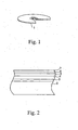
- Fig. 1 is a partial cut perspective view of an optical information recording medium 1 (hereafter, abbreviated as an optical disc) according to a preferred embodiment of the present invention.
- the optical disc 1 according to a preferred embodiment of the present invention is designed so as to enable a recording signal to be recorded and reproduced a plurality of times. For example, it is accommodated in a disc cartridge (not shown) and detachably used for a recording/reproducing apparatus (not shown).
- the optical disc 1 is designed such that a first dielectric layer 3, a signal recording/reproducing layer 4, a second dielectric layer 5, a thermally diffusing layer 6 and a protective layer 7 are sequentially laminated on a transparent disc substrate 2.
- the signal recording/reproducing layer 4 is composed of a reproducing layer, a middle layer and a recording layer.
- the optical disc 1 is configured such that the recording signal is recorded and reproduced along the grooves 2a and the lands 2b.
- a recording track through which the recording signal is recorded and reproduced is formed along the groove 2a.
- the signal recording on both of the groove and the land is done, in the transparent disc substrate 2 according to a preferred embodiment of the present invention.
- Fig. 4 is a view schematic showing an enlarged section of the land-groove shape of Fig. 3.
- Ra L and Ra G indicate a arithmetic average roughness on a land surface and a arithmetic average roughness on a groove surface, respectively.
- An inclination angle ⁇ of a groove side is an angle between the groove side and a horizontal surface of the transparent disc substrate 2.
- the inclination angle ⁇ of the groove side is 25° or more
- the arithmetic average roughness Ra L on the land surface and the arithmetic average roughness on the groove surface Ra G are both between 0.2 and 0.7 nm.
- the arithmetic average roughness (Ra) is the value in which only a standard length (l) is extracted from a roughness curve in a direction of its average line, and the absolute values of deviations from the average line of the extracted portion to a measurement curve are totaled and averaged. It is calculated from the following equation.
- the reproduction of information was done by using the Magnetically Induced Super Resolution (MSR).
- MSR Magnetically Induced Super Resolution
- the optical disc 1 was formed by sequentially forming the first dielectric layer 3, the signal recording/reproducing layer 4, the second dielectric layer 5, the thermally diffusing layer 6 and the protective layer 7 on the transparent disc substrate 2 having the above-mentioned configuration by using a typical method, as shown in Fig. 2.
- the first dielectric layer 3, the signal recording/reproducing layer 4, the second dielectric layer 5 and the thermally diffusing layer 6 were' formed by using a sputtering method
- the protective layer 7 was formed by using a spin coating method.
- the substrate was defined as 1.2 mm
- the first dielectric layer 3 (SiN) was defined as 80 nm.
- the signal recording/reproducing layer 4 is composed of the reproducing layer (GdFeCo) 40 nm, the middle layer (GdFe) 30 nm and the recording layer (TbFeCo) 50 nm.
- the second dielectric layer 5 (SiN) was defined as 20 nm
- the thermally diffusing layer 6 (AlTi) was defined as 10 nm
- the protective layer 7 (ultraviolet curing resin) was defined as 10 ⁇ m.
- the signal recording/reproducing layer 4 constituting the optical disc 1 includes an optically magnetically recording layer in this embodiment.
- the optically magnetically recording layer may be formed as a single layer, or may be formed as a multiple-layer structure. Also, the concave convex shapes of the grooves 2a and the lands 2b in the transparent disc substrate 2 are transferred to the signal recording/reproducing layer 4.
- the disc substrate having the arithmetic average roughness on the land surface and the groove surface and the inclination angle of the groove side as shown in a table 1 was used to carry out an experiment to evaluate the jitters, the erasability and the power margin properties, as indicated by the graphs in Figs. 5 to 7. The experiment was done under the condition of the same film configurations.
- the comparative example 2 was the conventional product.
- Sample Arithmetic average roughness of land surface Arithmetic average roughness of groove surface Inclination angle of groove side surface
- Example of embodiment 1 0.6nm 0.55nm 25°
- Comparative example 1 0.7nm 0.65nm 19°
- Comparative example 2 0.8nm 0.4nm 40°
- Fig. 5 shows the jitters in the respective examples
- Fig. 6 shows the erasability
- Fig. 7 shows the power margin properties.
- the power margin property indicates a level of difficulty of occurrence of crosstalk.
- a wavelength of a reading laser light is 650 nm
- NA Numerical Aperture
- a line velocity is 7.5 m per second.
- steps 1, 2 may be done by replacement by the following steps 1', 2' in which the land and the groove are respectively exchanged at the respective steps.
- steps 1, 2 may be done by replacement by the following steps 1', 2' in which the land and the groove are respectively exchanged at the respective steps.
- steps 1, 2, 3 and 5 may be done by replacement by the following steps 1', 2', 3' and 5' in which the land and the groove are respectively exchanged at the respective steps.
- the improvement of the arithmetic average roughness on the land surface leads to a good balance to the arithmetic average roughness on the groove surface.
- Fig. 7 shows the power margin property and indicates the resistance against the crosstalk.
- the inclination angle ⁇ of the groove side it may be typically inferred that as it becomes gentler, the crosstalk is increased to thereby drop the reading performance, namely, reduce the power margin.
- the power margin is kept without any deterioration. Then, it is said that the balance between both of the land and the groove is kept.
- the inclination angle of the groove side in the comparative example 1 is 19°, the power margin is largely deteriorated.
- the control of the shapes of the groove and the land on the substrate enables the crosstalk, the jitter and the magnetic property in the tracks of both of the land and the groove to be simultaneously satisfied, which was difficult with the conventional techniques.
- the optical information recording medium 1 can be produced by using the transparent disc substrate 2 having the above-mentioned shape.
- this disc substrate can be obtained by manufacturing and using an original disc of an optical information recording medium, which will be described below. This is because even the shape (the inclination angle and the arithmetic average roughness) of the optical disc after it is molded is similar to a stamper (original disc).
- the manufacturing method of the original disc for the optical information recording medium is the manufacturing method of the original disc for the optical information recording medium, which transfers and produces a substrate for the optical information recording medium that has both a land and a groove as a recording track. It is characterized by including: a step of producing the shapes of the land and the groove on an original disc material surface; and a step of performing a plasma etching process on the original disc material surface, on which the shapes of the land and the groove are formed, and setting an inclination angle of an original disc surface corresponding to the groove side to 25° or more and 40° or less, and then setting both of the arithmetic average roughness (Ra) on the original disc surfaces corresponding to the land surface and the groove surface to 0.2 to 0.7 nm.
- Ra arithmetic average roughness
- a surface of a glass plate 10 serving as a source to produce an original disc is polished and washed (Fig. 8A), and a resist 11 is applied on the surface of the glass plate 10 (Fig. 8B).
- a surface of the resist 11 is exposed and cut through a laser beam 17 so that the shape of the track is left (Fig. 8C).
- the resist 11 is developed and washed to thereby complete a glass plate 18, in which a concave convex track resulting from a resist remainder 12 is formed on the surface (Fig. 8D).
- a thin nickel film 13 is deposited, for example, through sputtering non-electrolytic plating and the like. Consequently, the surface is made conductive (Fig. 8E). Then, the nickel plating is performed on the surface to thereby form a nickel plating layer 14 (Fig. 8F).
- This nickel plating layer 14 is stripped from the glass plate 18, and a washing and a reverse polishing are performed thereon to thereby complete an original disc 15 made of nickel (Figs. 8G, 8H). Then, the plasma etching process is performed on the entire surface of this original disc 15 made of nickel (Fig. 8I).
- the step of producing the shapes of the land and the groove on the original disc material surface in this embodiment is the step illustrated at Figs. 8A to 8H.
- various methods of the known techniques can be applied thereto.
- the nickel plating method described here is one of them.
- the original disc material is not limited to the above-mentioned nickel material.
- the original disc 15 made of the nickel completed at the first step is characterized in that since the land surface is plated on the resist surface of the rough surface state, the arithmetic average roughness on the original disc surface corresponding to the land surface is rough.
- the land surface is at a rougher state than the groove surface, and the balance between the arithmetic average roughness on the original disc surfaces corresponding to the land surface and the groove surface is not good.
- the optical disc obtained in this case is the conventional example, and it corresponds to the comparative example 2 in the above-mentioned tables 1, 2.
- the plasma etching process is further performed on the original disc material surface on which the shapes of the land and the groove are formed.
- the inclination angle of the original disc surface corresponding to the groove surface is set to 25° or more and 40° or less, and both the arithmetic average roughness (Ra) on the original disc surfaces corresponding to the land surface and the groove surface are set to 0.2 to 0.7 nm.
- the plasma etching process uses an apparatus of a parallel flat plate type and a substrate cathode installation type.
- the used plasma etching gas is Ar gas.
- an RF power; an Ar gas pressure and a processing time are 150 W, 10 Pa and 3 min (the example of embodiment 1), and 150 W, 10 Pa and 5 min (the comparative example 1), respectively.
- An etching rate of the nickel film under this condition is about 10 nm/min, and the measurement is done by using an Atomic Force Microscope (AFM).
- AFM Atomic Force Microscope
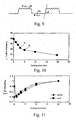
- Fig. 10 is a graph showing the relationship between the plasma etching time according to this embodiment and the inclination angle of the original disc surface corresponding to the groove surface
- Fig. 11 is a graph showing the relation between the plasma etching time according to this embodiment and the arithmetic average roughness on the original disc surfaces corresponding to the land surface and the groove surface.
- the inclination angle ⁇ of the original disc surface corresponding to the groove side is more obtuse in association with the plasma etching time, because of an angular dependency of an etching speed in an anisotropic etching.
- the inclination angle is 40° at an initial state. However, for example, it is about 25° (an A-part of Fig. 10) at three minutes in the example of embodiment 1, and 19° (a B-part of Fig. 10) at five minutes of the comparative example 1.
- the arithmetic average roughness (Ra) on the original disc surfaces corresponding to the land surface and the groove surface are basically located in the direction of the deterioration caused by ion impact.
- the land surface is plated on the resist surface of the rough surface state and formed at the first step. Thus, it is rough at the initial state. For this reason, the arithmetic average roughness is improved at the initial period of the plasma etching process.
- the arithmetic average roughness on the original disc surface corresponding to the land surface at the initial state, which was rough is transiently improved by the plasma etching process. After that, if the plasma etching process is continued in its original state, the effect of the plasma etching causes the surface to be rough, namely, the arithmetic average roughness is improved in a monotonously increasing manner.
- the method of stopping the etching after the elapse of a certain time and maintaining the condition that the arithmetic average roughness on the land and the groove are close to each other contributes to the improvement of the signal quality, such as the improvement of the crosstalk property and the like.
- the plasma etching method can be used to control the arithmetic average roughness on the original disc surfaces corresponding to the land surface and the groove surface, and the control of the arithmetic average roughness as mentioned above enables the signal control to be improved.
- the plasma etching through the Ar gas is used.
- other types of gas for example, N 2 , He and O 2 .
- the comparison between the properties of the above-manufactured disc according to the preferred embodiment of the present invention and the disc of the conventional product is illustrated in the above-mentioned table 2. That is, in the example of embodiment 1, the etching time is 3 minutes, and the inclination angle of the groove side is 25°. Thus, the arithmetic average roughness on both of the groove surface and the land surface are suppressed to the low values, and its balance is good. Hence, the signal quality such as the jitter and the like is optimum.
- the comparative example 2 is a conventional product, and it is at a state that the plasma etching process according to the preferred embodiment of the present invention is not done.
- the inclination angle of the groove side is wide, and the balance between the arithmetic average roughness on the land surface and the groove surface is poor.
- the power margin property is optimum, the jitter and the erasability are poor.
- the etching processing time according to the preferred embodiment of the present invention is defined as 5 minutes.
- the inclination angle of the groove side is 19°.
- the optical information recording medium according to the preferred embodiment of the present invention the original disc for the optical information recording medium and the method of manufacturing the same can provide the following advantages.
- the recording on both surfaces of the land and the groove can be attained without any drop in the recording quality.
- the jitters, the erasability and the power margin properties with regard to both surfaces of the land and the groove can be suitably balanced.
- they can be improved, depending on only the shape, irrespective of the property of the signal recording film.
- the effect of the optical information recording medium according to the preferred embodiment of the present invention can be especially provided in the MSR method of increasing the recording density in the circumferential direction.
- the original disc for the optical information recording medium according to the preferred embodiment of the present invention and the method of manufacturing the same, a mass-production of the above-mentioned recording medium can be attained. Also, the plasma etching can be used to easily control the arithmetic average roughness on the original disc surfaces corresponding to the land surface and the groove surface.
Landscapes
- Engineering & Computer Science (AREA)
- Manufacturing & Machinery (AREA)
- Manufacturing Optical Record Carriers (AREA)
- Optical Record Carriers And Manufacture Thereof (AREA)
Applications Claiming Priority (3)
| Application Number | Priority Date | Filing Date | Title |
|---|---|---|---|
| JP2001200498A JP4147753B2 (ja) | 2001-07-02 | 2001-07-02 | 光情報記録媒体、光情報記録媒体用原盤およびその製造方法 |
| JP2001200498 | 2001-07-02 | ||
| PCT/JP2002/006445 WO2003005353A1 (en) | 2001-07-02 | 2002-06-26 | Optical information recording medium, original disk for optical information recording medium, and method of manufacturing the original disk |
Publications (3)
| Publication Number | Publication Date |
|---|---|
| EP1406253A1 true EP1406253A1 (de) | 2004-04-07 |
| EP1406253A4 EP1406253A4 (de) | 2008-03-05 |
| EP1406253B1 EP1406253B1 (de) | 2010-11-24 |
Family
ID=19037610
Family Applications (1)
| Application Number | Title | Priority Date | Filing Date |
|---|---|---|---|
| EP02741348A Expired - Lifetime EP1406253B1 (de) | 2001-07-02 | 2002-06-26 | Verfahren zur herstellung einer originalplatte für ein optisches informationsaufzeichnungsmedium |
Country Status (8)
| Country | Link |
|---|---|
| US (2) | US6986152B2 (de) |
| EP (1) | EP1406253B1 (de) |
| JP (1) | JP4147753B2 (de) |
| KR (2) | KR20090046969A (de) |
| CN (1) | CN1240063C (de) |
| DE (1) | DE60238406D1 (de) |
| TW (1) | TWI228254B (de) |
| WO (1) | WO2003005353A1 (de) |
Cited By (1)
| Publication number | Priority date | Publication date | Assignee | Title |
|---|---|---|---|---|
| US6986152B2 (en) | 2001-07-02 | 2006-01-10 | Sony Corporation | Optical information recording medium |
Families Citing this family (15)
| Publication number | Priority date | Publication date | Assignee | Title |
|---|---|---|---|---|
| JP4244527B2 (ja) * | 2001-04-06 | 2009-03-25 | ソニー株式会社 | 光ディスクの製造方法 |
| TWI254934B (en) * | 2002-04-26 | 2006-05-11 | Tdk Corp | Optical recording medium and method for optically recording data in the same |
| JP4282285B2 (ja) * | 2002-08-12 | 2009-06-17 | Tdk株式会社 | 光記録媒体及び光記録方法 |
| US20050188397A1 (en) * | 2002-12-24 | 2005-08-25 | Fujitsu Limited | Magneto-optical recording medium and magneto-optical recording medium substrate manufacturing method |
| US20040202097A1 (en) * | 2003-04-08 | 2004-10-14 | Tdk Corporation | Optical recording disk |
| JP2004355783A (ja) * | 2003-05-30 | 2004-12-16 | Sharp Corp | 光情報記録媒体とその再生方法 |
| JP2005235358A (ja) * | 2004-02-23 | 2005-09-02 | Tdk Corp | 磁気記録媒体 |
| JP4665531B2 (ja) * | 2005-01-27 | 2011-04-06 | 日立電線株式会社 | 配線板の製造方法 |
| JP4468191B2 (ja) * | 2005-01-27 | 2010-05-26 | 株式会社日立製作所 | 金属構造体及びその製造方法 |
| JP2007035164A (ja) * | 2005-07-27 | 2007-02-08 | Toshiba Corp | 凹凸パターン基板およびその製造方法、磁気記録媒体、ならびに磁気記録装置 |
| JP4585476B2 (ja) * | 2006-03-16 | 2010-11-24 | 株式会社東芝 | パターンド媒体および磁気記録装置 |
| US20080038705A1 (en) * | 2006-07-14 | 2008-02-14 | Kerns Daniel R | System and method for assessing student progress and delivering appropriate content |
| JP2008142895A (ja) * | 2006-12-05 | 2008-06-26 | Fujifilm Corp | モールド構造体 |
| JP4621898B2 (ja) * | 2007-09-21 | 2011-01-26 | 独立行政法人産業技術総合研究所 | 超解像再生を行うための光記録媒体及びその光記録再生方法 |
| WO2009104293A1 (ja) * | 2008-02-18 | 2009-08-27 | セイコーインスツル株式会社 | 圧電振動子の製造方法、圧電振動子、発振器、電子機器及び電波時計 |
Family Cites Families (31)
| Publication number | Priority date | Publication date | Assignee | Title |
|---|---|---|---|---|
| JPH0648546B2 (ja) * | 1984-07-14 | 1994-06-22 | 日本ビクター株式会社 | 情報記録担体の製造法 |
| JPS6486344A (en) * | 1987-09-29 | 1989-03-31 | Victor Company Of Japan | Information recording carrier and production thereof |
| JPH01205744A (ja) * | 1988-02-12 | 1989-08-18 | Victor Co Of Japan Ltd | スタンパ複製用原盤とその製造方法 |
| JP2506967B2 (ja) * | 1988-08-03 | 1996-06-12 | 松下電器産業株式会社 | 光ディスク原盤の製造方法 |
| EP0376678B1 (de) * | 1988-12-28 | 1995-03-01 | Canon Kabushiki Kaisha | Informationsaufzeichnungsträger |
| JPH0554440A (ja) * | 1991-08-20 | 1993-03-05 | Sanyo Electric Co Ltd | 光デイスク用スタンパの製造方法 |
| US5768075A (en) * | 1991-12-17 | 1998-06-16 | Baradun R&D Ltd. | Disk medium w/magnetically filled features aligned in rows and columns |
| JPH05198016A (ja) * | 1992-01-21 | 1993-08-06 | Sharp Corp | 光メモリ素子用原盤及びその製造方法 |
| JPH05250742A (ja) | 1992-03-04 | 1993-09-28 | Kuraray Co Ltd | 光磁気記録媒体およびその製造に用いるスタンパー |
| WO1995028705A1 (en) * | 1994-04-18 | 1995-10-26 | Sony Corporation | Substrate for optical recording media and stamper for manufacturing substrate for optical recording media |
| JPH09161336A (ja) * | 1995-12-05 | 1997-06-20 | Teijin Ltd | 光記録媒体用スタンパの製造方法 |
| WO1997038421A1 (fr) * | 1996-04-10 | 1997-10-16 | Hitachi Maxell, Ltd. | Support d'enregistrement optique |
| JPH1064131A (ja) * | 1996-08-19 | 1998-03-06 | Fujitsu Ltd | 光磁気記録媒体及びその製造方法 |
| JPH1092016A (ja) * | 1996-09-12 | 1998-04-10 | Nikon Corp | 光ディスク |
| KR100230449B1 (ko) | 1996-10-10 | 1999-11-15 | 윤종용 | 광기록매체 |
| JP3255051B2 (ja) | 1996-12-05 | 2002-02-12 | 三菱化学株式会社 | 光学的情報記録用媒体 |
| KR19990023151A (ko) * | 1997-08-27 | 1999-03-25 | 사토 도리 | 광자기기록매체 및 그 재생방법 |
| JP3472158B2 (ja) | 1997-10-16 | 2003-12-02 | キヤノン株式会社 | 光磁気記録媒体 |
| US6177175B1 (en) * | 1997-10-16 | 2001-01-23 | Canon Kabushiki Kaisha | Magneto-optical medium utilizing domain wall displacement |
| US6814897B2 (en) * | 1998-03-27 | 2004-11-09 | Discovision Associates | Method for manufacturing a molding tool used for substrate molding |
| JPH11353711A (ja) * | 1998-06-04 | 1999-12-24 | Victor Co Of Japan Ltd | 光ディスク |
| JP2000104184A (ja) | 1998-07-06 | 2000-04-11 | Victor Co Of Japan Ltd | ドライエッチング装置、ドライエッチング方法、被ドライエッチング部材 |
| JP2000048401A (ja) | 1998-07-31 | 2000-02-18 | Victor Co Of Japan Ltd | 光情報記録媒体 |
| JP2000293901A (ja) * | 1999-04-02 | 2000-10-20 | Canon Inc | 情報記録媒体及びその製造方法 |
| JP2000339778A (ja) * | 1999-05-26 | 2000-12-08 | Sony Corp | 光ディスク用原盤およびその製造方法、並びに、光ディスク用原盤の製造装置 |
| JP2001126328A (ja) | 1999-10-29 | 2001-05-11 | Sony Corp | 光磁気記録媒体 |
| TW505915B (en) * | 2000-02-14 | 2002-10-11 | Taiyo Yuden Kk | Optical information recording medium, method for recording/reproducing the same, and optical pickup |
| US6501728B2 (en) * | 2000-04-21 | 2002-12-31 | Sony Corporation | Optical disc having groove and land tracks |
| JP4244527B2 (ja) * | 2001-04-06 | 2009-03-25 | ソニー株式会社 | 光ディスクの製造方法 |
| JP4147753B2 (ja) | 2001-07-02 | 2008-09-10 | ソニー株式会社 | 光情報記録媒体、光情報記録媒体用原盤およびその製造方法 |
| TW200511296A (en) * | 2003-09-01 | 2005-03-16 | Matsushita Electric Industrial Co Ltd | Method for manufacturing stamper, stamper and optical recording medium |
-
2001
- 2001-07-02 JP JP2001200498A patent/JP4147753B2/ja not_active Expired - Fee Related
-
2002
- 2002-06-26 EP EP02741348A patent/EP1406253B1/de not_active Expired - Lifetime
- 2002-06-26 US US10/344,700 patent/US6986152B2/en not_active Expired - Fee Related
- 2002-06-26 KR KR1020097007002A patent/KR20090046969A/ko not_active Ceased
- 2002-06-26 DE DE60238406T patent/DE60238406D1/de not_active Expired - Lifetime
- 2002-06-26 CN CNB028025156A patent/CN1240063C/zh not_active Expired - Fee Related
- 2002-06-26 KR KR10-2003-7002862A patent/KR20030033038A/ko not_active Ceased
- 2002-06-26 WO PCT/JP2002/006445 patent/WO2003005353A1/ja not_active Ceased
- 2002-07-02 TW TW091114624A patent/TWI228254B/zh not_active IP Right Cessation
-
2004
- 2004-08-30 US US10/928,186 patent/US7294281B2/en not_active Expired - Fee Related
Cited By (2)
| Publication number | Priority date | Publication date | Assignee | Title |
|---|---|---|---|---|
| US6986152B2 (en) | 2001-07-02 | 2006-01-10 | Sony Corporation | Optical information recording medium |
| US7294281B2 (en) | 2001-07-02 | 2007-11-13 | Sony Corporation | Optical information recording medium, original disc for optical information recording medium, and method of manufacturing the same |
Also Published As
| Publication number | Publication date |
|---|---|
| WO2003005353A1 (en) | 2003-01-16 |
| US7294281B2 (en) | 2007-11-13 |
| EP1406253B1 (de) | 2010-11-24 |
| EP1406253A4 (de) | 2008-03-05 |
| US20050028184A1 (en) | 2005-02-03 |
| CN1240063C (zh) | 2006-02-01 |
| US20040066732A1 (en) | 2004-04-08 |
| CN1465055A (zh) | 2003-12-31 |
| JP2003016696A (ja) | 2003-01-17 |
| JP4147753B2 (ja) | 2008-09-10 |
| TWI228254B (en) | 2005-02-21 |
| KR20030033038A (ko) | 2003-04-26 |
| KR20090046969A (ko) | 2009-05-11 |
| DE60238406D1 (de) | 2011-01-05 |
| US6986152B2 (en) | 2006-01-10 |
Similar Documents
| Publication | Publication Date | Title |
|---|---|---|
| US6986152B2 (en) | Optical information recording medium | |
| US6127017A (en) | Substrate for information recording disk, mold and stamper for injection molding substrate, and method for making stamper, and information recording disk | |
| US6177175B1 (en) | Magneto-optical medium utilizing domain wall displacement | |
| US6203877B1 (en) | Optical information recording medium | |
| US7914711B2 (en) | Use of mother stamper for optical disk molding | |
| US20050042427A1 (en) | Method for manufacturing stamper for information medium manufacture, stamper, and stamper intermediate with master disk | |
| EP1081687B1 (de) | Magnetaufzeichnungsmedium und dessen Herstellungsverfahren | |
| JP2003296972A (ja) | 情報記録媒体及びその製造方法 | |
| US20050066825A1 (en) | Method for manufacturing stamper for information medium manufacture, stamper, and photoresist original disk | |
| KR20030024838A (ko) | 요철을 갖는 광기록 매체 제작용 원반, 스탬퍼, 광기록매체의 각각의 제조방법 | |
| JP2848992B2 (ja) | 光記録媒体及びそれに用いる光記録媒体用基板 | |
| CN1327419C (zh) | 磁光记录介质 | |
| US5700540A (en) | Optical recording medium | |
| US6808823B2 (en) | Magneto-optical recording medium and manufacturing method therefor | |
| Umezawa et al. | UV laser mastering with a multilayer coating method producing land/groove type of optical disk with track pitch of 0.3 µm or less | |
| JP2003141787A (ja) | 光記録媒体及びその製造方法 | |
| JPH10320858A (ja) | 光磁気記録媒体 | |
| JP2002109784A (ja) | 光記録媒体 | |
| JPH08273228A (ja) | 光磁気記録媒体の製造方法 | |
| Briaud et al. | A New Fabrication Process For Compact Disk | |
| JPH05109144A (ja) | 複合型記録デイスク及びその製造方法 | |
| JP2003109258A (ja) | 光記録媒体 | |
| JP2001143337A (ja) | 光磁気記録媒体 | |
| JPH02246031A (ja) | 光ディスク | |
| JPH0969244A (ja) | 光磁気ディスク |
Legal Events
| Date | Code | Title | Description |
|---|---|---|---|
| PUAI | Public reference made under article 153(3) epc to a published international application that has entered the european phase |
Free format text: ORIGINAL CODE: 0009012 |
|
| 17P | Request for examination filed |
Effective date: 20030227 |
|
| AK | Designated contracting states |
Kind code of ref document: A1 Designated state(s): AT BE CH CY DE DK ES FI FR GB GR IE IT LI LU MC NL PT SE TR |
|
| A4 | Supplementary search report drawn up and despatched |
Effective date: 20080201 |
|
| 17Q | First examination report despatched |
Effective date: 20080605 |
|
| RIC1 | Information provided on ipc code assigned before grant |
Ipc: G11B 7/24 20060101AFI20100104BHEP |
|
| RTI1 | Title (correction) |
Free format text: METHOD OF MANUFACTURING AN ORIGINAL DISK FOR OPTICAL INFORMATION RECORDING MEDIUM |
|
| GRAP | Despatch of communication of intention to grant a patent |
Free format text: ORIGINAL CODE: EPIDOSNIGR1 |
|
| RBV | Designated contracting states (corrected) |
Designated state(s): DE FR GB |
|
| GRAS | Grant fee paid |
Free format text: ORIGINAL CODE: EPIDOSNIGR3 |
|
| GRAA | (expected) grant |
Free format text: ORIGINAL CODE: 0009210 |
|
| AK | Designated contracting states |
Kind code of ref document: B1 Designated state(s): DE FR GB |
|
| REG | Reference to a national code |
Ref country code: GB Ref legal event code: FG4D |
|
| REF | Corresponds to: |
Ref document number: 60238406 Country of ref document: DE Date of ref document: 20110105 Kind code of ref document: P |
|
| PLBE | No opposition filed within time limit |
Free format text: ORIGINAL CODE: 0009261 |
|
| STAA | Information on the status of an ep patent application or granted ep patent |
Free format text: STATUS: NO OPPOSITION FILED WITHIN TIME LIMIT |
|
| 26N | No opposition filed |
Effective date: 20110825 |
|
| REG | Reference to a national code |
Ref country code: DE Ref legal event code: R097 Ref document number: 60238406 Country of ref document: DE Effective date: 20110825 |
|
| REG | Reference to a national code |
Ref country code: GB Ref legal event code: 746 Effective date: 20120702 |
|
| REG | Reference to a national code |
Ref country code: DE Ref legal event code: R084 Ref document number: 60238406 Country of ref document: DE Effective date: 20120614 |
|
| PGFP | Annual fee paid to national office [announced via postgrant information from national office to epo] |
Ref country code: FR Payment date: 20120705 Year of fee payment: 11 Ref country code: GB Payment date: 20120622 Year of fee payment: 11 |
|
| PGFP | Annual fee paid to national office [announced via postgrant information from national office to epo] |
Ref country code: DE Payment date: 20120822 Year of fee payment: 11 |
|
| GBPC | Gb: european patent ceased through non-payment of renewal fee |
Effective date: 20130626 |
|
| REG | Reference to a national code |
Ref country code: FR Ref legal event code: ST Effective date: 20140228 |
|
| REG | Reference to a national code |
Ref country code: DE Ref legal event code: R119 Ref document number: 60238406 Country of ref document: DE Effective date: 20140101 |
|
| PG25 | Lapsed in a contracting state [announced via postgrant information from national office to epo] |
Ref country code: DE Free format text: LAPSE BECAUSE OF NON-PAYMENT OF DUE FEES Effective date: 20140101 Ref country code: GB Free format text: LAPSE BECAUSE OF NON-PAYMENT OF DUE FEES Effective date: 20130626 |
|
| PG25 | Lapsed in a contracting state [announced via postgrant information from national office to epo] |
Ref country code: FR Free format text: LAPSE BECAUSE OF NON-PAYMENT OF DUE FEES Effective date: 20130701 |