EP1407129B1 - Thermische verbesserungen für einen motor mit äusserer verbrennung - Google Patents
Thermische verbesserungen für einen motor mit äusserer verbrennung Download PDFInfo
- Publication number
- EP1407129B1 EP1407129B1 EP02780808A EP02780808A EP1407129B1 EP 1407129 B1 EP1407129 B1 EP 1407129B1 EP 02780808 A EP02780808 A EP 02780808A EP 02780808 A EP02780808 A EP 02780808A EP 1407129 B1 EP1407129 B1 EP 1407129B1
- Authority
- EP
- European Patent Office
- Prior art keywords
- heater
- flow
- tube
- heater tubes
- tubes
- Prior art date
- Legal status (The legal status is an assumption and is not a legal conclusion. Google has not performed a legal analysis and makes no representation as to the accuracy of the status listed.)
- Expired - Lifetime
Links
- 238000002485 combustion reaction Methods 0.000 title claims abstract description 47
- 239000012530 fluid Substances 0.000 claims abstract description 39
- 238000011144 upstream manufacturing Methods 0.000 claims description 9
- 239000000446 fuel Substances 0.000 claims description 4
- 239000002184 metal Substances 0.000 claims description 4
- 229910052751 metal Inorganic materials 0.000 claims description 4
- 239000007789 gas Substances 0.000 description 81
- 238000012546 transfer Methods 0.000 description 40
- 230000006835 compression Effects 0.000 description 10
- 238000007906 compression Methods 0.000 description 10
- 239000000567 combustion gas Substances 0.000 description 9
- 229910001119 inconels 625 Inorganic materials 0.000 description 6
- 239000000463 material Substances 0.000 description 6
- 229910045601 alloy Inorganic materials 0.000 description 5
- 239000000956 alloy Substances 0.000 description 5
- 229910000856 hastalloy Inorganic materials 0.000 description 5
- 229910001055 inconels 600 Inorganic materials 0.000 description 5
- 229910001220 stainless steel Inorganic materials 0.000 description 5
- PXHVJJICTQNCMI-UHFFFAOYSA-N Nickel Chemical compound [Ni] PXHVJJICTQNCMI-UHFFFAOYSA-N 0.000 description 4
- 238000010438 heat treatment Methods 0.000 description 4
- 238000000034 method Methods 0.000 description 4
- 229910000990 Ni alloy Inorganic materials 0.000 description 3
- 239000000919 ceramic Substances 0.000 description 3
- 239000001307 helium Substances 0.000 description 3
- 229910052734 helium Inorganic materials 0.000 description 3
- SWQJXJOGLNCZEY-UHFFFAOYSA-N helium atom Chemical compound [He] SWQJXJOGLNCZEY-UHFFFAOYSA-N 0.000 description 3
- 230000005855 radiation Effects 0.000 description 3
- IJGRMHOSHXDMSA-UHFFFAOYSA-N Atomic nitrogen Chemical compound N#N IJGRMHOSHXDMSA-UHFFFAOYSA-N 0.000 description 2
- 238000001816 cooling Methods 0.000 description 2
- 230000007423 decrease Effects 0.000 description 2
- 238000009826 distribution Methods 0.000 description 2
- -1 for example Substances 0.000 description 2
- 238000004519 manufacturing process Methods 0.000 description 2
- 238000012986 modification Methods 0.000 description 2
- 230000004048 modification Effects 0.000 description 2
- 229910052759 nickel Inorganic materials 0.000 description 2
- 238000013021 overheating Methods 0.000 description 2
- 238000013459 approach Methods 0.000 description 1
- 238000004891 communication Methods 0.000 description 1
- 239000012141 concentrate Substances 0.000 description 1
- 238000005336 cracking Methods 0.000 description 1
- 230000001419 dependent effect Effects 0.000 description 1
- 238000011161 development Methods 0.000 description 1
- 238000010586 diagram Methods 0.000 description 1
- 238000000605 extraction Methods 0.000 description 1
- 239000011159 matrix material Substances 0.000 description 1
- 239000000203 mixture Substances 0.000 description 1
- 229910052757 nitrogen Inorganic materials 0.000 description 1
- 238000000926 separation method Methods 0.000 description 1
- 125000006850 spacer group Chemical group 0.000 description 1
- 238000003466 welding Methods 0.000 description 1
Images


Classifications
-
- F—MECHANICAL ENGINEERING; LIGHTING; HEATING; WEAPONS; BLASTING
- F02—COMBUSTION ENGINES; HOT-GAS OR COMBUSTION-PRODUCT ENGINE PLANTS
- F02G—HOT GAS OR COMBUSTION-PRODUCT POSITIVE-DISPLACEMENT ENGINE PLANTS; USE OF WASTE HEAT OF COMBUSTION ENGINES; NOT OTHERWISE PROVIDED FOR
- F02G1/00—Hot gas positive-displacement engine plants
- F02G1/04—Hot gas positive-displacement engine plants of closed-cycle type
- F02G1/043—Hot gas positive-displacement engine plants of closed-cycle type the engine being operated by expansion and contraction of a mass of working gas which is heated and cooled in one of a plurality of constantly communicating expansible chambers, e.g. Stirling cycle type engines
- F02G1/053—Component parts or details
- F02G1/055—Heaters or coolers
-
- F—MECHANICAL ENGINEERING; LIGHTING; HEATING; WEAPONS; BLASTING
- F02—COMBUSTION ENGINES; HOT-GAS OR COMBUSTION-PRODUCT ENGINE PLANTS
- F02G—HOT GAS OR COMBUSTION-PRODUCT POSITIVE-DISPLACEMENT ENGINE PLANTS; USE OF WASTE HEAT OF COMBUSTION ENGINES; NOT OTHERWISE PROVIDED FOR
- F02G1/00—Hot gas positive-displacement engine plants
- F02G1/04—Hot gas positive-displacement engine plants of closed-cycle type
- F02G1/043—Hot gas positive-displacement engine plants of closed-cycle type the engine being operated by expansion and contraction of a mass of working gas which is heated and cooled in one of a plurality of constantly communicating expansible chambers, e.g. Stirling cycle type engines
-
- F—MECHANICAL ENGINEERING; LIGHTING; HEATING; WEAPONS; BLASTING
- F02—COMBUSTION ENGINES; HOT-GAS OR COMBUSTION-PRODUCT ENGINE PLANTS
- F02G—HOT GAS OR COMBUSTION-PRODUCT POSITIVE-DISPLACEMENT ENGINE PLANTS; USE OF WASTE HEAT OF COMBUSTION ENGINES; NOT OTHERWISE PROVIDED FOR
- F02G2255/00—Heater tubes
Definitions
- the present invention pertains to components of an external combustion engine and, more particularly, to thermal improvements relating to the heater head assembly of an external combustion engine, such as a Stirling cycle engine, which contribute to increased engine operating efficiency and lifetime.
- FIG 1 is a cross-sectional view of an expansion cylinder and tube heater head of an illustrative Stirling cycle engine.
- a typical configuration of a tube heater head 108 uses a cage of U-shaped heater tubes 118 surrounding a combustion chamber 110 .
- An expansion cylinder 102 contains a working fluid, such as, for example, helium. The working fluid is displaced by the expansion piston 104 and driven through the heater tubes 118 .
- a burner 116 combusts a combination of fuel and air to produce hot combustion gases that are used to heat the working fluid through the heater tubes 118 by conduction.
- the heater tubes 118 connect a regenerator 106 with the expansion cylinder 102 .
- the regenerator 106 may be a matrix of material having a large ratio of surface to area volume which serves to absorb heat from the working fluid or to heat the working fluid during the cycles of the engine.
- Heater tubes 118 provide a high surface area and a high heat transfer coefficient for the flow of the combustion gases past the heater tubes 118 .
- several problems may occur with prior art tube heater head designs such as inefficient heat transfer, localized overheating of the heater tubes and cracked tubes.
- Stirling cycle machines including engines and refrigerators, have a long technological heritage, described in detail in Walker, Stirling Engines, Oxford University Press (1980 ), incorporated herein by reference.
- the principle underlying the Stirling cycle engine is the mechanical realization of the Stirling thermodynamic cycle: isovolumetric heating of a gas within a cylinder, isothermal expansion of the gas (during which work is performed by driving a piston), isovolumetric cooling, and isothermal compression.
- the Stirling cycle refrigerator is also the mechanical realization of a thermodynamic cycle that approximates the ideal Stirling thermodynamic cycle.
- the working fluid is chosen for its thermodynamic properties, as discussed in the description below, and is typically helium at a pressure of several atmospheres.
- the position of displacer 206 governs whether the working fluid is in contact with hot interface 208 or cold interface 212 , corresponding, respectively, to the interfaces at which heat is supplied to and extracted from the working fluid. The supply and extraction of heat is discussed in further detail below.
- the volume of working fluid governed by the position of the piston 202 is referred to as compression space 214 .
- piston 202 compresses the fluid in compression space 214 .
- the compression occurs at a substantially constant temperature because heat is extracted from the fluid to the ambient environment.
- the condition of engine 200 after compression is depicted in Figure 2b .
- displacer 206 moves in the direction of cold interface 212 , with the working fluid displaced from the region of cold interface 212 to the region of hot interface 208 .
- the phase may be referred to as the transfer phase.
- the fluid is at a higher pressure since the working fluid has been heated at a constant volume.
- the increased pressure is depicted symbolically in Figure 2c by the reading of pressure gauge 204 .
- the volume of compression space 214 increases as heat is drawn in from outside engine 200 , thereby converting heat to work.
- heat is provided to the fluid by means of a heater head 108 (shown in Figure 1 ) which is discussed in greater detail in the description below.
- compression space 214 is full of cold fluid, as depicted in Figure 2d .
- fluid is transferred from the region of hot interface 208 to the region of cold interface 212 by motion of displacer 206 in the opposing sense.
- the fluid fills compression space 214 and cold interface 212 , as depicted in Figure 2a , and is ready for a repetition of the compression phase.
- the Stirling cycle is depicted in a P-V (pressure-volume) diagram shown in Figure 2e .
- an external combustion engine of the type having a piston undergoing reciprocating linear motion within an expansion cylinder containing a working fluid heated by heat from an external source that is conducted through a heater head having a plurality of heater tubes.
- the external combustion engine has an exhaust flow diverter for directing the flow of an exhaust gas past the plurality of heater tubes.
- the exhaust flow diverter comprises a cylinder disposed around the outside of the plurality of heater tubes, the cylinder having a plurality of openings through which the flow of exhaust gas may pass.
- the exhaust flow diverter directs the flow of the exhaust gas in a flow path characterized by a direction past a downstream side of each outer heater tube in the plurality of heater tubes.
- Each opening in the plurality of openings may be positioned in line with a heater tube in the plurality of heater tubes. At least one opening in the plurality of openings may have a width equal to the diameter of a heater tube in the plurality of heater tubes.
- the exhaust flow diverter further includes a set of heat transfer fins thermally connected to the exhaust flow diverter. Each heat transfer fin is placed outboard of an opening and directs the flow of the exhaust gas along the exhaust flow diverter.
- the exhaust flow diverter directs the radial flow of the exhaust gas in a flow path characterized by a direction along the longitudinal axis of the plurality of heater tubes. Each opening in the plurality of openings may have the shape of a slot and have a width that increases in the direction of the flow path.
- the exhaust flow diverter further includes a plurality of dividing structures inboard of the plurality of openings for spatially separating each heater tube in the plurality of heater tubes.
- the improvement consists of a combustion chamber liner for directing the flow of the exhaust gas past a plurality of heater tubes of the heater head.
- the combustion chamber liner comprises a cylinder disposed between the combustion chamber and the inside of the plurality of heater tubes.
- the combustion chamber liner has a plurality of openings through which exhaust gas may pass.
- the plurality of heater tubes includes inner heater tube sections proximal to the combustion chamber and outer heater tube sections distal to the combustion chamber. The plurality of openings directs the exhaust gas between the inner heater tube sections.
- an external combustion engine that includes a plurality of flow diverter fins thermally connected to a plurality of heater tubes of a heater head.
- Each flow diverter fin in the plurality of flow diverter fins direct the flow of an exhaust gas in a circumferential flow path around an adjacent heater tube.
- Each flow diverter fin is thermally connected to a heater tube along the entire length of the flow diverter fin.
- each flow diverter fin has an L shaped cross section.
- the flow diverter fins on adjacent heater tubes overlap one another.
- a Stirling cycle engine of the type having a piston undergoing reciprocating linear motion within an expansion cylinder containing a working fluid heated by heat from an external source through a heater head.
- the Stirling cycle engine has a heat exchanger comprising a plurality of heater tubes in the form of helical coils that are coupled to the heater head.
- the plurality of helical coiled heater tubes transfer heat from the exhaust gas to the working fluid as the working fluid passes through the heater tubes.
- the helical coiled heater tubes are position on the heater head to form a combustion chamber.
- each helical coiled heater tube has a helical coiled portion and a straight return portion that is placed on the outside of the helical coiled portion.
- each helical coiled heater tube has a helical coiled portion and a straight return portion that is placed inside of the helical coiled portion.
- each helical coiled heater tube is a double helix. The straight return portion of each helical coiled heater tube may be aligned with a gap between the helical coiled heater tube and an adjacent helical coiled heater tube.
- the Stirling cycle engine includes a heater tube cap placed on top of the plurality of helical coiled heater tubes to prevent a flow of the exhaust gas out of the top of the plurality of helical coiled heater tubes.
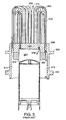
- FIG 3 is a side view in cross section of a tube heater head and an expansion cylinder.
- Heater head 306 is substantially a cylinder having one closed end 320 (otherwise referred to as the cylinder head) and an open end 322 .
- Closed end 320 includes a plurality of U-shaped heater tubes 304 that are disposed in a burner 436 (shown in Figure 4 ).
- Each U-shaped tube 304 has an outer portion 316 (otherwise referred to herein as an "outer heater tube”) and an inner portion 318 (otherwise referred to herein as an "inner heater tube”).
- the heater tubes 304 connect the expansion cylinder 302 to regenerator 310 .
- Expansion cylinder 302 is disposed inside heater head 306 and is also typically supported by the heater head 306 .
- An expansion piston 324 travels along the interior of expansion cylinder 302 . As the expansion piston 324 travels toward the closed end 320 of the heater head 306 , working fluid within the expansion cylinder 302 is displaced and caused to flow through the heater tubes 304 and regenerator 310 as illustrated by arrows 330 and 332 in Figure 3 .
- a burner flange 308 provides an attachment surface for a burner 436 (shown in Figure 4 ) and a cooler flange 312 provides an attachment surface for a cooler (not shown).
- the closed end of heater head 406 is disposed in a burner 436 that includes a combustion chamber 438 .
- Hot combustion gases (otherwise referred to herein as "exhaust gases”) in combustion chamber 438 are in direct thermal contact with heater tubes 404 of heater head 406 .
- Thermal energy is transferred by conduction from the exhaust gases to the heater tubes 404 and from the heater tubes 404 to the working fluid of the engine, typically helium.
- gases such as nitrogen, for example, or mixtures of gases, may be used within the scope of the present invention, with a preferable working fluid having high thermal conductivity and low viscosity.
- Non-combustible gases are also preferred.
- Heat is transferred from the exhaust gases to the heater tubes 404 as the exhaust gases flow around the surfaces of the heater tubes 404 .
- Arrows 442 show the general radial direction of flow of the exhaust gases.
- Arrows 440 show the direction of flow of the exhaust gas as it exits from the burner 436 .
- the exhaust gases exiting from the burner 436 tend to overheat the upper part of the heater tubes 404 (near the U-bend) because the flow of the exhaust gases is greater near the upper part of the heater tubes than at the bottom of the heater tubes (i.e., near the bottom of the burner 436 ).
- the overall efficiency of an external combustion engine is dependent in part on the efficiency of heat transfer between the combustion gases and the working fluid of the engine.
- the inner heater tubes 318 are warmer than the outer heater tubes 316 by several hundred degrees Celsius. The burner power and thus the amount of heating provided to the working fluid is therefore limited by the inner heater tube 318 temperatures. The maximum amount of heat will be transferred to the working gas if the inner and outer heater tubes are nearly the same temperature.
- embodiments of the invention, as described herein either increase the heat transfer to the outer heater tubes or decrease the rate of heat transfer to the inner heater tubes.
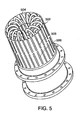
- FIG. 5 is a perspective view of an exhaust flow concentrator and a tube heater head not belonging to the invention.
- Heat transfer to a cylinder, such as a heater- tube, in cross-flow is generally limited to only the upstream half of the tube. Heat transfer on the back side (or downstream half) of the tube, however, is nearly zero due to flow separation and recirculation.
- An exhaust flow concentrator 502 may be used to improve heat transfer from the exhaust gases to the downstream side of the outer heater tubes by directing the flow of hot exhaust gases around the downstream side (i.e. the back side) of the outer heater tubes. As shown in Figure 5 , exhaust flow concentrator 502 is a cylinder placed outside the bank of heater tubes 504 .
- the exhaust flow concentrator 502 may be fabricated from heat resistant alloys, preferably high nickel alloys such as Inconel 600, Inconel 625, Stainless Steels 310 and 316 and more preferably Hastelloy X. Openings 506 in the exhaust flow concentrator 502 are lined up with the outer heater tubes.
- the openings 506 may be any number of shapes such as a slot, round hole, oval hole, square hole etc. In Figure 5 , the openings 506 are shown as slots.
- the slots 506 may have a width approximately equal to the diameter of a heater tube 504.
- the exhaust flow concentrator 502 is preferably a distance from the outer heater tubes equivalent to one to two heater tube diameters.
- Figure 6 illustrates the flow of exhaust gases using the exhaust flow concentrator as shown in Figure 5 .
- heat transfer is generally limited to the upstream side 610 of a heater tube 604 .
- the exhaust flow concentrator 602 uses the exhaust flow concentrator 602 to force through openings 606 as shown by arrows 612 .
- the exhaust flow concentrator 602 increases the exhaust gas flow 612 past the downstream side 614 of the heater tubes 604 .
- the increased exhaust gas flow past the downstream side 614 of the heater tubes 604 improves the heat transfer from the exhaust gases to the downstream side 614 of the heater tubes 604 . This in turn increases the efficiency of heat transfer to the working fluid which can increase the overall efficiency and power of the engine.
- the exhaust flow concentrator 502 may also improve the heat transfer to the downstream side of the heater tubes 504 by radiation. Referring to Figure 7 , given enough heat transfer between the exhaust gases and the exhaust flow concentrator, the temperature of the exhaust flow concentrator 702 will approach the temperature of the exhaust gases. The exhaust flow concentrator 702 may not carry any load and may therefore, operate at 1000 °C or higher. In contrast, the heater tubes 704 generally operate at 700 °C. Due to the temperature difference, the exhaust flow concentrator 702 may then radiate thermally to the much cooler heater tubes 704 thereby increasing the heat transfer to the heater tubes 704 and the working fluid of the engine.
- Heat transfer surfaces (or fins) 710 may be added to the exhaust flow concentrator 702 to increase the amount of thermal energy captured by the exhaust flow concentrator 702 that may then be transferred to the heater tubes by radiation. Fins 710 are coupled to the exhaust flow concentrator 702 at positions outboard of and between the openings 706 so that the exhaust gas flow is directed along the exhaust flow concentrator, thereby reducing the radiant thermal energy lost through each opening in the exhaust flow concentrator.
- the fins 710 are preferably attached to the exhaust flow concentrator 702 through spot welding. Alternatively, the fins 710 may be welded or brazed to the exhaust flow concentrator 702 .
- the fins 710 should be fabricated from the same material as the exhaust flow concentrator 702 to minimize differential thermal expansion and subsequent cracking.
- the fins 710 may be fabricated from heat resistant alloys, preferably high nickel alloys such as Inconel 600, Inconel 625, Stainless Steels 310 and 316 and more preferably Hastelloy X.
- FIG. 8 is a perspective view of an exhaust flow axial equalizer not belonging to the invention.
- the exhaust flow axial equalizer 820 is used to improve the distribution of the exhaust gases along the longitudinal axis of the heater tubes 804 as the exhaust gases flow radially out of the tube heater head. (The typical radial flow of the exhaust gases is shown in Figure 4 .) As shown in Figure 8 , the exhaust flow axial equalizer 820 is a cylinder with openings 822 . As mentioned above, the openings 822 may be any number of shapes such as a slot, round hole, oval hole, square hole etc.
- the exhaust flow axial equalizer 820 may be fabricated from heat resistant alloys, preferably high nickel alloys including Inconel 600, Inconel 625, Stainless Steels 310 and 316 and more preferably Hastelloy X.
- the exhaust flow axial equalizer 820 may be placed outside of the heater tubes 804 and an exhaust flow concentrator 802 .
- the exhaust flow axial equalizer 820 may be used by itself (i.e., without an exhaust flow concentrator 802 ) and placed outside of the heater tubes 804 to improve the heat transfer from the exhaust gases to the heater tubes 804 .
- the openings 822 of the exhaust flow axial equalizer 820 are shaped so that they provide a larger opening at the bottom of the heater tubes 804 . In other words, as shown in Figure 8 , the width of the openings 822 increases from top to bottom along the longitudinal axis of the heater tubes 804 .
- the increased exhaust gas flow area through the openings 822 of the exhaust flow axial equalizer 820 near the lower portions of the heater tubes 804 counteracts the tendency of the exhaust gas flow to concentrate near the top of the heater tubes 804 and thereby equalizes the axial distribution of the radial exhaust gas flow along the longitudinal axis of the heater tubes 804 .
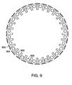
- spacing elements 904 may be added to an exhaust flow concentrator 902 to reduce the spacing between the heater tubes 906 .
- the spacing elements 904 could be added to an exhaust flow axial equalizer 820 (shown in Figure 8 ) when it is used without the exhaust flow concentrator 904 .
- the spacing elements 904 are placed inboard of and between the openings. The spacers 904 create a narrow exhaust flow channel that forces the exhaust gas to increase its speed past the sides of heater tubes 906 . The increased speed of the combustion gas thereby increases the heat transfer from the combustion gases to the heater tubes 906 .
- the spacing elements may also improve the heat transfer to the heater tubes 906 by radiation.
- Figure 10 is a cross-sectional side view of a tube heater head 1006 and burner 1008 not belonging to the invention.
- a combustion chamber of a burner 1008 is placed inside a set of heater tubes 1004 as opposed to above the set of heater tubes 1004 as shown in Figure 4 .
- a perforated combustion chamber liner 1015 is placed between the combustion chamber and the heater tubes 1004 . Perforated combustion chamber liner 1015 protects the inner heater tubes from direct impingement by the flames in the combustion chamber.
- the perforated combustion chamber liner 1015 equalizes the radial exhaust gas flow along the longitudinal axis of the heater tubes 1004 so that the radial exhaust gas flow across the top of the heater tubes 1004 (near the U-bend) is roughly equivalent to the radial exhaust gas flow across the bottom of the heater tubes 1004 .
- the openings in the perforated combustion chamber liner 1015 are arranged so that the combustion gases exiting the perforated combustion chamber liner 1015 pass between the inner heater tubes 1004 . Diverting the combustion gases away from the upstream side of the inner heater tubes 1004 will reduce the inner heater tube temperature, which in turn allows for a higher burner power and a higher engine power.
- An exhaust flow concentrator 1002 may be placed outside of the heater tubes 1004 . The exhaust flow concentrator 1002 is described above with respect to Figures 5 and 6 .
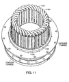
- FIG 11 is a perspective view of a tube heater head including flow diverter fins in accordance with an embodiment of the invention.
- Flow diverter fins 1102 are used to direct the exhaust gas flow around the heater tubes 1104 , including the downstream side of the heater tubes 1104 , in order to increase the heat transfer from the exhaust gas to the heater tubes 1104 .
- Flow diverter fin 1102 is thermally connected to a heater tube 1104 along the entire length of the flow diverter fin. Therefore, in addition to directing the flow of the exhaust gas, flow diverter fins 1102 increase the surface area for the transfer of heat by conduction to the heater tubes 1104 , and thence to the working fluid.
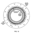
- Figure 12 is a top view in cross-section of a tube heater head including flow diverter fins in accordance with an embodiment of the invention.
- the outer heater tubes 1206 have a large inter-tube spacing. Therefore, as shown in Figure 12 , the flow diverter fins 1202 are used on the outer heater tubes 1206 .
- the flow diverter fins could be placed on the inner heater tubes 1208 .
- a pair of flow diverter fins is connected to each outer heater tube 1206 .
- One flow diverter fin is attached to the upstream side of the heater tube and one flow diverter fin is attached to the downstream side of the heater tube.
- the flow diverter fins 1202 are "L" shaped in cross section as shown in Figure 12 .
- Each flow diverter fin 1202 is brazed to an outer heater tube so that the inner (or upstream) flow diverter fin of one heater tube overlaps with the outer (or downstream) flow diverter fin of an adjacent heater tube to form a serpentine flow channel.
- the path of the exhaust gas flow caused by the flow diverter fins is shown by arrows 1214 .
- the thickness of the flow diverter fins 1202 decreases the size of the exhaust gas flow channel thereby increasing the speed of the exhaust gas flow. This, in turn, results in improved heat transfer to the outer heater tubes 1206 .
- the flow diverter fins 1202 also increase the surface area of the outer heater tubes 1206 for the transfer of heat by conduction to the outer heater tubes 1206 .
- Figure 13 is a cross-sectional top view of a section of the tube heater head of Figure 11 in accordance with an embodiment of the invention.
- a pair of flow diverter fins 1302 is brazed to each of the outer heater tubes 1306 .
- the flow diverter fins 1302 are attached to an outer heater tube 1306 using a nickel braze along the full length of the heater tube.
- the flow diverter fins could be brazed with other high temperature materials, welded or joined using other techniques known in the art that provide a mechanical and thermal bond between the flow diverter fin and the heater tube.
- FIG 14 is a top view of a section of a tube heater head including single flow diverter fins in accordance with an embodiment of the invention.
- a single flow diverter fin 1402 is connected to each outer heater tube 1404 .
- the flow diverter fins 1402 are attached to an outer heater tube 1404 using a nickel braze along the full length of the heater tube.
- the flow diverter fins may be brazed with other high temperature materials, welded or joined using other techniques known in the art that provide a mechanical and thermal bond between the flow diverter fin and the heater tube.
- Flow diverter fins 1402 are used to direct the exhaust gas flow around the heater tubes 1404 , including the downstream side of the heater tubes 1404 .
- flow diverter fins 1402 are thermally connected to the heater tube 1404 . Therefore, in addition to directing the flow of exhaust gas, flow diverter fins 1402 increase the surface area for the transfer of heat by conduction to the heater tubes 1404 , and thence to the working fluid.
- Figure 15 is a top view in cross-section of a section of a tube heater head including the single flow diverter fins as shown in Figure 14 in accordance with an embodiment of the invention.
- a flow diverter fin 1510 is placed on the upstream side of a heater tube 1506 .
- the diverter fin 1510 is shaped so as to maintain a constant distance from the downstream side of the heater tube 1506 and therefore improve the transfer of heat to the heater tube 1506 .
- the flow diverter fins could be placed on the inner heater tubes 1508 .
- Engine performance in terms of both power and efficiency, is highest at the highest possible temperature of the working gas in the expansion volume of the engine.
- the maximum working gas temperature is typically limited by the properties of the heater head.
- the maximum temperature is limited by the metallurgical properties of the heater tubes. If the heater tubes become too hot, they may soften and fail resulting in engine shut down. Alternatively, at too high of a temperature the tubes will be severely oxidized and fail. It is, therefore, important to engine performance to control the temperature of the heater tubes.
- a temperature sensing device such as a thermocouple, may be used to measure the temperature of the heater tubes.
- FIG 16 is a side view in cross section of an expansion cylinder 1604 and a burner 1610 in accordance with an embodiment of the invention.
- a temperature sensor 1602 is used to monitor the temperature of the heater tubes and provide feedback to a fuel controller (not shown) of the engine in order to maintain the heater tubes at the desired temperature.
- the heater tubes are fabricated using Inconel 625 and the desired temperature is 930°C. The desired temperature will be different for other heater tube materials.
- the temperature sensor 1602 should be placed at the hottest, and therefore the limiting, part of the heater tubes. Generally, the hottest part of the heater tubes will be the upstream side of an inner heater tube 1606 near the top of the heater tube.
- Figure 16 shows the placement of the temperature sensor 1602 on the upstream side of an inner heater tube 1606 .
- the temperature sensor 1602 is c lamped to the heater tube with a strip of metal 1612 that is welded to the heater tube in order to provide good thermal contact between the temperature sensor 1602 and the heater tube 1606 .
- both the heater tubes 1606 and the metal strip 1612 may be Inconel 625 or other heat resistant alloys such as Inconel 600, Stainless Steels 310 and 316 and Hastelloy X.
- the temperature sensor 1602 should be in good thermal contact with the heater tube, otherwise it may read too high a temperature and the engine will not produce as much power as possible.
- the temperature sensor sheath may be welded directly to the heater tube.
- the U-shaped heater tubes may be replaced with several helical wound heater tubes.
- fewer helical shaped heater tubes are required to achieve similar heat transfer between the exhaust gases and the working fluid. Reducing the number of heater tubes reduces the material and fabrication costs of the heater head.
- a helical heater tube does not require the additional fabrication steps of forming and attaching fins.
- a helical heater tube provides fewer joints that could fail, thus increasing the reliability of the heater head.
- FIGS. 17a-17d are perspective views of a helical heater tube not belonging to the invention.
- the helical heater tube, 1702 as shown in Figure 17a , may be formed from a single long piece of tubing by wrapping the tubing around a mandrel to form a tight helical coil 1704 . The tube is then bent around at a right angle to create a straight return passage out of the helix 1706 . The right angle may be formed before the final helical loop is formed so that the return can be clocked to the correct angle.
- Figures 17b and 17c show further views of the helical heater tube.
- Figure 17d shows an alternative embodiment of the helical heater tube in which the straight return passage 1706 goes through the center of the helical coil 1704 .
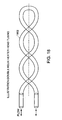
- Figure 18 shows a helical heater tube not belonging to the invention.
- the helical heater tube 1802 is shaped as a double helix.
- the heater tube 1802 may be formed using a U-shaped tube wound to form a double helix.
- FIG 19 is a perspective view of a tube heater head with helical heater tubes (as shown in Figure 17a ) not belonging to the invention.
- Helical heater tubes 1902 are mounted in a circular pattern o the top of a heater head 1903 to form a combustion chamber 1906 in the center of the helical heater tubes 1902 .
- the helical heater tubes 1902 provide a significant amount of heat exchange surface around the outside of the combustion chamber 1906 .
- FIG 20 is a cross sectional view of a burner and a tube heater head with helical heater tubes not belonging to the invention.
- Helical heater tubes 2002 connect the hot end of a regenerator 2004 to an expansion cylinder 2005 .
- the helical heater tubes 2002 are arranged to form a combustion chamber 2006 for a burner 2007 that is mounted coaxially and above the helical heater tubes 2002 .
- Fuel and air are mixed in a throat 2008 of the burner 2007 and combusted in the combustion chamber 2006 .
- the hot combustion (or exhaust) gases flow, as shown by arrows 2014 , across the helical heater tubes 2002 , providing heat to the working fluid as it passes through the helical heater tubes 2002 .
- the heater head 2003 may include a heater tube cap 2010 at the top of each helical coiled heater tubes 2002 to prevent the exhaust gas from entering the helical coil portion 2001 of each heater tube and exiting out the top of the coil. Further, an annular shaped piece of metal covers the top of all of the helical coiled heater tubes.
- the heater tube cap 2010 prevents the flow of the exhaust gas along the heater head axis to the top of the helical heater tubes between the helical heater tubes.
- the heater tube cap 2010 may be Inconel 625 or other heat resistant alloys such as Inconel 600, Stainless Steels 310 and 316 and Hastelloy X.
- the top of the heater head 2003 under the helical heater tubes 2002 may be covered with a moldable ceramic paste.
- the ceramic paste insulates the heater head 2003 from impingement heating by the flames in the combustion chamber 2006 as well as from the exhaust gases.
- the ceramic blocks the flow of the exhaust gases along the heater head axis to the bottom of the helical heater tubes 2002 either between the helical heater tubes 2002 or inside the helical coil portion 2001 of each heater tube.
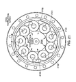
- FIG. 21 is a top view of a tube heater head with helical heater tubes not belonging to the invention.
- the return or straight section 2102 of each helical heater tube 2100 is advantageously placed outboard of gap 2109 between adjacent helical heater tubes 2100 . It is important to balance the flow of exhaust gases through the helical heater tubes 2100 with the flow of exhaust gases through the gaps 2109 between the helical heater tubes 2100 .
- the straight portion 2102 of the helical heater tube outboard of the gap 2109 the pressure drop for exhaust gas passing through the helical heater tubes is increased, thereby forcing more of the exhaust gas through the helical coils where the heat transfer and heat exchange area are high.
Landscapes
- Engineering & Computer Science (AREA)
- Chemical & Material Sciences (AREA)
- Combustion & Propulsion (AREA)
- Mechanical Engineering (AREA)
- General Engineering & Computer Science (AREA)
- Heat-Exchange Devices With Radiators And Conduit Assemblies (AREA)
- Cylinder Crankcases Of Internal Combustion Engines (AREA)
- Exhaust Silencers (AREA)
Claims (7)
- Verbrennungsmaschine mit äußerer Verbrennung von der Art, die einen Kolben hat, der eine lineare Pendelbewegung ausführt, innerhalb eines Ausdehnungszylinders, der ein Arbeitsmedium beinhaltet, das mittels einer Wärmeleitung eines Heizkopfes, der eine Vielzahl von Heizleiterrohren (1104, 1206) hat, von der Wärme des Auspuffgases eines externen Brenners beheizt wird, gekennzeichnet dadurch, dass diese beinhaltet:eine Vielzahl von Fluss-Umlenk-Leitschaufeln (1102, 1202, 1302), die thermisch mit der Vielzahl von Heizleiterrohren (1104, 1206) verbunden sind, wobei jede Fluss-Umlenk-Leitschaufel (1102, 1202, 1302) in der Vielzahl von Fluss-Umlenk-Leitschaufeln mechanisch und thermisch mit einem Heizleiterrohr verbunden ist und den Fluss des Auspuffgases umlenkt, um die Durchflussgeschwindigkeit des Auspuffgases an einem benachbarten Heizleiterrohr vorbei zu erhöhen, wobei jede Fluss-Umlenk-Leitschaufel thermisch mit einem Heizleiterrohr entlang einer wesentlichen Länge der Fluss-Umlenk-Leitschaufel verbunden ist.
- Verbrennungsmaschine mit äußerer Verbrennung nach Anspruch 1, wobei die Fluss-Umlenk-Leitschaufel (1302) einen L-förmigen Querschnitt hat.
- Verbrennungsmaschine mit äußerer Verbrennung nach Anspruch 1, wobei sich die Fluss-Umlenk-Leitschaufeln (1302) mit benachbarten Heizleiterrohren überlappen.
- Verbrennungsmaschine mit äußerer Verbrennung nach Anspruch 1, wobei die Verbrennungsmaschine mit äußerer Verbrennung eine Kräftstoffversorgung hat, und die Maschine ferner einen Temperatur-Sensor beinhaltet, um die Temperatur von wenigstens einem Heizleiterrohr (1206) von der Vielzahl der Heizleiterrohre zu messen, und der Temperatur-Sensor thermisch mit wenigstens einem Heizleiterrohr an einem Punkt der höchsten Temperatur des Heizleiterrohrs verbunden ist.
- Verbrennungsmaschine mit äußerer Verbrennung nach Anspruch 4, wobei der Temperatur-Sensor ein Thermoelement ist.
- Verbrennungsmaschine mit äußerer Verbrennung nach Anspruch 4, wobei der Punkt der höchsten Temperatur flussaufwärtsseitig des wenigstens einen Heizleiterrohrs ist.
- Verbrennungsmaschine mit äußerer Verbrennung nach Anspruch 4, wobei der Temperatur-Sensor mit dem wenigstens einen Heizleitrohr unter der Verwendung eines metallischen Bandes thermisch verbunden ist.
Applications Claiming Priority (3)
| Application Number | Priority Date | Filing Date | Title |
|---|---|---|---|
| US883077 | 1978-03-03 | ||
| US09/883,077 US6543215B2 (en) | 2001-06-15 | 2001-06-15 | Thermal improvements for an external combustion engine |
| PCT/US2002/018467 WO2002103185A1 (en) | 2001-06-15 | 2002-06-12 | Thermal improvements for an external combustion engine |
Publications (2)
| Publication Number | Publication Date |
|---|---|
| EP1407129A1 EP1407129A1 (de) | 2004-04-14 |
| EP1407129B1 true EP1407129B1 (de) | 2008-11-19 |
Family
ID=25381926
Family Applications (1)
| Application Number | Title | Priority Date | Filing Date |
|---|---|---|---|
| EP02780808A Expired - Lifetime EP1407129B1 (de) | 2001-06-15 | 2002-06-12 | Thermische verbesserungen für einen motor mit äusserer verbrennung |
Country Status (7)
| Country | Link |
|---|---|
| US (2) | US6543215B2 (de) |
| EP (1) | EP1407129B1 (de) |
| AT (1) | ATE414845T1 (de) |
| CA (1) | CA2450287C (de) |
| DE (1) | DE60229945D1 (de) |
| MX (1) | MXPA03011536A (de) |
| WO (1) | WO2002103185A1 (de) |
Families Citing this family (39)
| Publication number | Priority date | Publication date | Assignee | Title |
|---|---|---|---|---|
| US6543215B2 (en) * | 2001-06-15 | 2003-04-08 | New Power Concepts Llc | Thermal improvements for an external combustion engine |
| US7111460B2 (en) * | 2000-03-02 | 2006-09-26 | New Power Concepts Llc | Metering fuel pump |
| US7308787B2 (en) * | 2001-06-15 | 2007-12-18 | New Power Concepts Llc | Thermal improvements for an external combustion engine |
| US7810317B2 (en) * | 2002-03-27 | 2010-10-12 | Precision Combustion, Inc. | Catalytic burner utilizing electrosprayed fuels |
| US8069676B2 (en) | 2002-11-13 | 2011-12-06 | Deka Products Limited Partnership | Water vapor distillation apparatus, method and system |
| US8511105B2 (en) | 2002-11-13 | 2013-08-20 | Deka Products Limited Partnership | Water vending apparatus |
| MXPA05005245A (es) | 2002-11-13 | 2005-09-08 | Deka Products Lp | Destilacion con presurizacion de vapor. |
| US20050008272A1 (en) * | 2003-07-08 | 2005-01-13 | Prashant Bhat | Method and device for bearing seal pressure relief |
| GB0328292D0 (en) * | 2003-12-05 | 2004-01-07 | Microgen Energy Ltd | A stirling engine assembly |
| US7310945B2 (en) | 2004-02-06 | 2007-12-25 | New Power Concepts Llc | Work-space pressure regulator |
| US7007470B2 (en) * | 2004-02-09 | 2006-03-07 | New Power Concepts Llc | Compression release valve |
| WO2005108865A1 (en) * | 2004-05-06 | 2005-11-17 | New Power Concepts Llc | Gaseous fuel burner |
| EP1772083A4 (de) * | 2004-07-29 | 2008-05-14 | Guangzhou Light Holdings Ltd | Multifunktionsbratofen |
| US7536943B2 (en) * | 2005-02-09 | 2009-05-26 | Edward Pritchard | Valve and auxiliary exhaust system for high efficiency steam engines and compressed gas motors |
| GB0522309D0 (en) * | 2005-11-01 | 2005-12-07 | Microgen Energy Ltd | An annular burner assembly |
| US20090113889A1 (en) * | 2006-02-28 | 2009-05-07 | Subir Roychoudhury | Catalytic burner for stirling engine |
| US8479508B2 (en) | 2006-02-28 | 2013-07-09 | Precision Combustion, Inc. | Catalytic burner apparatus for stirling engine |
| US8387380B2 (en) * | 2006-02-28 | 2013-03-05 | Precision Combustion, Inc. | Catalytic burner apparatus for Stirling Engine |
| US7913484B2 (en) * | 2006-02-28 | 2011-03-29 | Precision Combustion, Inc. | Catalytic burner apparatus for stirling engine |
| US11826681B2 (en) | 2006-06-30 | 2023-11-28 | Deka Products Limited Partneship | Water vapor distillation apparatus, method and system |
| CA2894441C (en) | 2007-04-23 | 2017-12-12 | New Power Concepts Llc | Stirling cycle machine |
| US8763391B2 (en) | 2007-04-23 | 2014-07-01 | Deka Products Limited Partnership | Stirling cycle machine |
| US11884555B2 (en) | 2007-06-07 | 2024-01-30 | Deka Products Limited Partnership | Water vapor distillation apparatus, method and system |
| US8505323B2 (en) | 2007-06-07 | 2013-08-13 | Deka Products Limited Partnership | Water vapor distillation apparatus, method and system |
| KR101826492B1 (ko) | 2007-06-07 | 2018-03-22 | 데카 프로덕츠 리미티드 파트너쉽 | 수증기 증류 장치, 방법 및 시스템 |
| US8359877B2 (en) | 2008-08-15 | 2013-01-29 | Deka Products Limited Partnership | Water vending apparatus |
| US8096118B2 (en) * | 2009-01-30 | 2012-01-17 | Williams Jonathan H | Engine for utilizing thermal energy to generate electricity |
| US9828940B2 (en) | 2009-07-01 | 2017-11-28 | New Power Concepts Llc | Stirling cycle machine |
| US9797341B2 (en) | 2009-07-01 | 2017-10-24 | New Power Concepts Llc | Linear cross-head bearing for stirling engine |
| EP2449244B1 (de) | 2009-07-01 | 2016-05-04 | New Power Concepts LLC | Stirling-zyklus-maschine |
| US9822730B2 (en) | 2009-07-01 | 2017-11-21 | New Power Concepts, Llc | Floating rod seal for a stirling cycle machine |
| US20140034475A1 (en) | 2012-04-06 | 2014-02-06 | Deka Products Limited Partnership | Water Vapor Distillation Apparatus, Method and System |
| WO2014018896A1 (en) | 2012-07-27 | 2014-01-30 | Deka Products Limited Partnership | Control of conductivity in product water outlet for evaporation apparatus |
| MX381181B (es) | 2013-03-15 | 2025-03-12 | New Power Concepts Llc | Maquina de ciclo stirling. |
| CA2942884C (en) | 2014-03-14 | 2020-11-03 | New Power Concepts Llc | Linear cross-head bearing for stirling engine |
| CN105756804B (zh) * | 2016-02-26 | 2017-12-12 | 中国科学院理化技术研究所 | 一种用于自由活塞斯特林发动机的热端换热器 |
| SE541818C2 (en) * | 2018-01-02 | 2019-12-17 | Maston AB | Stirling engine comprising flame guiding means |
| US11125184B2 (en) * | 2019-05-21 | 2021-09-21 | General Electric Company | Constant density heat exchanger and system for energy conversion |
| US11359836B2 (en) * | 2020-08-04 | 2022-06-14 | Rheem Manufacturing Company | Heat exchangers providing low pressure drop |
Family Cites Families (15)
| Publication number | Priority date | Publication date | Assignee | Title |
|---|---|---|---|---|
| GB675161A (en) | 1945-08-07 | 1952-07-09 | Philips Nv | Improvements in or relating to hot-gas reciprocating engines |
| GB704002A (en) | 1950-02-10 | 1954-02-17 | Philips Nv | Improvements in hot-gas reciprocating engines |
| GB892962A (en) | 1957-12-05 | 1962-04-04 | Philips Nv | Improvements in or relating to heat exchangers |
| SE426163B (sv) * | 1973-11-09 | 1982-12-13 | Quimco Gmbh | Sett att medelst joniserande stralar sterilisera avloppsslam och avloppsvatten |
| US4662176A (en) * | 1985-04-15 | 1987-05-05 | Mitsubishi Denki Kabushiki Kaisha | Heat exchanger for a Stirling engine |
| US4573320A (en) * | 1985-05-03 | 1986-03-04 | Mechanical Technology Incorporated | Combustion system |
| US4881372A (en) * | 1988-02-29 | 1989-11-21 | Aisin Seiki Kabushiki Kaisha | Stirling engine |
| US4901790A (en) | 1989-05-22 | 1990-02-20 | Stirling Thermal Motors, Inc. | Self-heated diffuser assembly for a heat pipe |
| JPH06507266A (ja) * | 1990-09-17 | 1994-08-11 | ストリクス リミテッド | 投げ込みヒータ |
| DE19612616C2 (de) | 1996-03-29 | 2002-03-07 | Sipra Patent Beteiligung | Stirlingmotor |
| US5755100A (en) * | 1997-03-24 | 1998-05-26 | Stirling Marine Power Limited | Hermetically sealed stirling engine generator |
| US6381958B1 (en) * | 1997-07-15 | 2002-05-07 | New Power Concepts Llc | Stirling engine thermal system improvements |
| US6247310B1 (en) * | 1997-07-15 | 2001-06-19 | New Power Concepts Llc | System and method for control of fuel and air delivery in a burner of a thermal-cycle engine |
| US6094912A (en) * | 1999-02-12 | 2000-08-01 | Stirling Technology Company | Apparatus and method for adaptively controlling moving members within a closed cycle thermal regenerative machine |
| US6543215B2 (en) * | 2001-06-15 | 2003-04-08 | New Power Concepts Llc | Thermal improvements for an external combustion engine |
-
2001
- 2001-06-15 US US09/883,077 patent/US6543215B2/en not_active Expired - Lifetime
-
2002
- 2002-06-12 AT AT02780808T patent/ATE414845T1/de not_active IP Right Cessation
- 2002-06-12 DE DE60229945T patent/DE60229945D1/de not_active Expired - Lifetime
- 2002-06-12 WO PCT/US2002/018467 patent/WO2002103185A1/en not_active Ceased
- 2002-06-12 CA CA2450287A patent/CA2450287C/en not_active Expired - Lifetime
- 2002-06-12 MX MXPA03011536A patent/MXPA03011536A/es active IP Right Grant
- 2002-06-12 EP EP02780808A patent/EP1407129B1/de not_active Expired - Lifetime
-
2003
- 2003-02-10 US US10/361,354 patent/US6857260B2/en not_active Expired - Lifetime
Also Published As
| Publication number | Publication date |
|---|---|
| CA2450287A1 (en) | 2002-12-27 |
| US20030145590A1 (en) | 2003-08-07 |
| US6857260B2 (en) | 2005-02-22 |
| US6543215B2 (en) | 2003-04-08 |
| CA2450287C (en) | 2011-04-05 |
| MXPA03011536A (es) | 2004-03-18 |
| ATE414845T1 (de) | 2008-12-15 |
| EP1407129A1 (de) | 2004-04-14 |
| DE60229945D1 (de) | 2009-01-02 |
| US20020189253A1 (en) | 2002-12-19 |
| WO2002103185A1 (en) | 2002-12-27 |
Similar Documents
| Publication | Publication Date | Title |
|---|---|---|
| EP1407129B1 (de) | Thermische verbesserungen für einen motor mit äusserer verbrennung | |
| US7654074B2 (en) | Thermal improvements for an external combustion engine | |
| US12078123B2 (en) | Stirling cycle machine | |
| KR100958476B1 (ko) | 스털링 엔진 열 시스템 개선 | |
| US4050250A (en) | Heat transfer element | |
| US5388409A (en) | Stirling engine with integrated gas combustor | |
| JPH0213149B2 (de) | ||
| AU2016204235B2 (en) | Stirling cycle machine | |
| JPS5865957A (ja) | スタ−リング機関 | |
| JPH01244151A (ja) | スターリングエンジン用高温熱交換器 | |
| JPS6079145A (ja) | スタ−リングエンジン | |
| JPH08105353A (ja) | 熱駆動装置 | |
| AU2014202629A1 (en) | Stirling cycle machine | |
| JPH0257220B2 (de) | ||
| JPH01240758A (ja) | スターリングエンジン | |
| JPS61223255A (ja) | スタ−リングエンジンの高温熱交換器 | |
| JPS63227944A (ja) | 空気予熱器 |
Legal Events
| Date | Code | Title | Description |
|---|---|---|---|
| PUAI | Public reference made under article 153(3) epc to a published international application that has entered the european phase |
Free format text: ORIGINAL CODE: 0009012 |
|
| 17P | Request for examination filed |
Effective date: 20040114 |
|
| AK | Designated contracting states |
Kind code of ref document: A1 Designated state(s): AT BE CH CY DE DK ES FI FR GB GR IE IT LI LU MC NL PT SE TR |
|
| AX | Request for extension of the european patent |
Extension state: AL LT LV MK RO SI |
|
| 17Q | First examination report despatched |
Effective date: 20060616 |
|
| GRAP | Despatch of communication of intention to grant a patent |
Free format text: ORIGINAL CODE: EPIDOSNIGR1 |
|
| GRAS | Grant fee paid |
Free format text: ORIGINAL CODE: EPIDOSNIGR3 |
|
| GRAA | (expected) grant |
Free format text: ORIGINAL CODE: 0009210 |
|
| AK | Designated contracting states |
Kind code of ref document: B1 Designated state(s): AT BE CH CY DE DK ES FI FR GB GR IE IT LI LU MC NL PT SE TR |
|
| REG | Reference to a national code |
Ref country code: GB Ref legal event code: FG4D |
|
| REG | Reference to a national code |
Ref country code: CH Ref legal event code: EP |
|
| REG | Reference to a national code |
Ref country code: IE Ref legal event code: FG4D |
|
| REF | Corresponds to: |
Ref document number: 60229945 Country of ref document: DE Date of ref document: 20090102 Kind code of ref document: P |
|
| PG25 | Lapsed in a contracting state [announced via postgrant information from national office to epo] |
Ref country code: ES Free format text: LAPSE BECAUSE OF FAILURE TO SUBMIT A TRANSLATION OF THE DESCRIPTION OR TO PAY THE FEE WITHIN THE PRESCRIBED TIME-LIMIT Effective date: 20090301 Ref country code: AT Free format text: LAPSE BECAUSE OF FAILURE TO SUBMIT A TRANSLATION OF THE DESCRIPTION OR TO PAY THE FEE WITHIN THE PRESCRIBED TIME-LIMIT Effective date: 20081119 |
|
| NLV1 | Nl: lapsed or annulled due to failure to fulfill the requirements of art. 29p and 29m of the patents act | ||
| PG25 | Lapsed in a contracting state [announced via postgrant information from national office to epo] |
Ref country code: FI Free format text: LAPSE BECAUSE OF FAILURE TO SUBMIT A TRANSLATION OF THE DESCRIPTION OR TO PAY THE FEE WITHIN THE PRESCRIBED TIME-LIMIT Effective date: 20081119 Ref country code: NL Free format text: LAPSE BECAUSE OF FAILURE TO SUBMIT A TRANSLATION OF THE DESCRIPTION OR TO PAY THE FEE WITHIN THE PRESCRIBED TIME-LIMIT Effective date: 20081119 |
|
| PG25 | Lapsed in a contracting state [announced via postgrant information from national office to epo] |
Ref country code: DK Free format text: LAPSE BECAUSE OF FAILURE TO SUBMIT A TRANSLATION OF THE DESCRIPTION OR TO PAY THE FEE WITHIN THE PRESCRIBED TIME-LIMIT Effective date: 20081119 Ref country code: BE Free format text: LAPSE BECAUSE OF FAILURE TO SUBMIT A TRANSLATION OF THE DESCRIPTION OR TO PAY THE FEE WITHIN THE PRESCRIBED TIME-LIMIT Effective date: 20081119 |
|
| PG25 | Lapsed in a contracting state [announced via postgrant information from national office to epo] |
Ref country code: SE Free format text: LAPSE BECAUSE OF FAILURE TO SUBMIT A TRANSLATION OF THE DESCRIPTION OR TO PAY THE FEE WITHIN THE PRESCRIBED TIME-LIMIT Effective date: 20090219 Ref country code: PT Free format text: LAPSE BECAUSE OF FAILURE TO SUBMIT A TRANSLATION OF THE DESCRIPTION OR TO PAY THE FEE WITHIN THE PRESCRIBED TIME-LIMIT Effective date: 20090420 |
|
| PLBE | No opposition filed within time limit |
Free format text: ORIGINAL CODE: 0009261 |
|
| STAA | Information on the status of an ep patent application or granted ep patent |
Free format text: STATUS: NO OPPOSITION FILED WITHIN TIME LIMIT |
|
| 26N | No opposition filed |
Effective date: 20090820 |
|
| PG25 | Lapsed in a contracting state [announced via postgrant information from national office to epo] |
Ref country code: MC Free format text: LAPSE BECAUSE OF NON-PAYMENT OF DUE FEES Effective date: 20090630 |
|
| REG | Reference to a national code |
Ref country code: CH Ref legal event code: PL |
|
| GBPC | Gb: european patent ceased through non-payment of renewal fee |
Effective date: 20090612 |
|
| REG | Reference to a national code |
Ref country code: IE Ref legal event code: MM4A |
|
| PG25 | Lapsed in a contracting state [announced via postgrant information from national office to epo] |
Ref country code: IE Free format text: LAPSE BECAUSE OF NON-PAYMENT OF DUE FEES Effective date: 20090612 Ref country code: LI Free format text: LAPSE BECAUSE OF NON-PAYMENT OF DUE FEES Effective date: 20090630 Ref country code: CH Free format text: LAPSE BECAUSE OF NON-PAYMENT OF DUE FEES Effective date: 20090630 |
|
| PG25 | Lapsed in a contracting state [announced via postgrant information from national office to epo] |
Ref country code: GB Free format text: LAPSE BECAUSE OF NON-PAYMENT OF DUE FEES Effective date: 20090612 |
|
| PG25 | Lapsed in a contracting state [announced via postgrant information from national office to epo] |
Ref country code: GR Free format text: LAPSE BECAUSE OF FAILURE TO SUBMIT A TRANSLATION OF THE DESCRIPTION OR TO PAY THE FEE WITHIN THE PRESCRIBED TIME-LIMIT Effective date: 20090220 |
|
| PG25 | Lapsed in a contracting state [announced via postgrant information from national office to epo] |
Ref country code: IT Free format text: LAPSE BECAUSE OF FAILURE TO SUBMIT A TRANSLATION OF THE DESCRIPTION OR TO PAY THE FEE WITHIN THE PRESCRIBED TIME-LIMIT Effective date: 20081119 |
|
| PG25 | Lapsed in a contracting state [announced via postgrant information from national office to epo] |
Ref country code: LU Free format text: LAPSE BECAUSE OF NON-PAYMENT OF DUE FEES Effective date: 20090612 |
|
| PG25 | Lapsed in a contracting state [announced via postgrant information from national office to epo] |
Ref country code: TR Free format text: LAPSE BECAUSE OF FAILURE TO SUBMIT A TRANSLATION OF THE DESCRIPTION OR TO PAY THE FEE WITHIN THE PRESCRIBED TIME-LIMIT Effective date: 20081119 |
|
| PG25 | Lapsed in a contracting state [announced via postgrant information from national office to epo] |
Ref country code: CY Free format text: LAPSE BECAUSE OF FAILURE TO SUBMIT A TRANSLATION OF THE DESCRIPTION OR TO PAY THE FEE WITHIN THE PRESCRIBED TIME-LIMIT Effective date: 20081119 |
|
| REG | Reference to a national code |
Ref country code: FR Ref legal event code: PLFP Year of fee payment: 15 |
|
| REG | Reference to a national code |
Ref country code: FR Ref legal event code: PLFP Year of fee payment: 16 |
|
| REG | Reference to a national code |
Ref country code: FR Ref legal event code: PLFP Year of fee payment: 17 |
|
| PGFP | Annual fee paid to national office [announced via postgrant information from national office to epo] |
Ref country code: DE Payment date: 20200629 Year of fee payment: 19 Ref country code: FR Payment date: 20200625 Year of fee payment: 19 |
|
| REG | Reference to a national code |
Ref country code: DE Ref legal event code: R119 Ref document number: 60229945 Country of ref document: DE |
|
| PG25 | Lapsed in a contracting state [announced via postgrant information from national office to epo] |
Ref country code: DE Free format text: LAPSE BECAUSE OF NON-PAYMENT OF DUE FEES Effective date: 20220101 |
|
| PG25 | Lapsed in a contracting state [announced via postgrant information from national office to epo] |
Ref country code: FR Free format text: LAPSE BECAUSE OF NON-PAYMENT OF DUE FEES Effective date: 20210630 |