EP1407979B1 - Schliessvorrichtung, mit Trichter Funktion, für Flüssigkeitsbehälter - Google Patents
Schliessvorrichtung, mit Trichter Funktion, für Flüssigkeitsbehälter Download PDFInfo
- Publication number
- EP1407979B1 EP1407979B1 EP03103672A EP03103672A EP1407979B1 EP 1407979 B1 EP1407979 B1 EP 1407979B1 EP 03103672 A EP03103672 A EP 03103672A EP 03103672 A EP03103672 A EP 03103672A EP 1407979 B1 EP1407979 B1 EP 1407979B1
- Authority
- EP
- European Patent Office
- Prior art keywords
- configuration
- closing device
- cup
- container
- funnel
- Prior art date
- Legal status (The legal status is an assumption and is not a legal conclusion. Google has not performed a legal analysis and makes no representation as to the accuracy of the status listed.)
- Expired - Lifetime
Links
- 239000007788 liquid Substances 0.000 title claims abstract description 30
- 238000007789 sealing Methods 0.000 claims 1
- 230000013011 mating Effects 0.000 description 2
- 238000012856 packing Methods 0.000 description 2
- 235000001674 Agaricus brunnescens Nutrition 0.000 description 1
- 244000273618 Sphenoclea zeylanica Species 0.000 description 1
- 238000007792 addition Methods 0.000 description 1
- 239000003795 chemical substances by application Substances 0.000 description 1
- 230000008878 coupling Effects 0.000 description 1
- 238000010168 coupling process Methods 0.000 description 1
- 238000005859 coupling reaction Methods 0.000 description 1
- 230000001419 dependent effect Effects 0.000 description 1
- 239000000428 dust Substances 0.000 description 1
- 238000012986 modification Methods 0.000 description 1
- 230000004048 modification Effects 0.000 description 1
- 230000000149 penetrating effect Effects 0.000 description 1
- 239000007787 solid Substances 0.000 description 1
Images

Classifications
-
- B—PERFORMING OPERATIONS; TRANSPORTING
- B65—CONVEYING; PACKING; STORING; HANDLING THIN OR FILAMENTARY MATERIAL
- B65D—CONTAINERS FOR STORAGE OR TRANSPORT OF ARTICLES OR MATERIALS, e.g. BAGS, BARRELS, BOTTLES, BOXES, CANS, CARTONS, CRATES, DRUMS, JARS, TANKS, HOPPERS, FORWARDING CONTAINERS; ACCESSORIES, CLOSURES, OR FITTINGS THEREFOR; PACKAGING ELEMENTS; PACKAGES
- B65D51/00—Closures not otherwise provided for
- B65D51/24—Closures not otherwise provided for combined or co-operating with auxiliary devices for non-closing purposes
-
- B—PERFORMING OPERATIONS; TRANSPORTING
- B65—CONVEYING; PACKING; STORING; HANDLING THIN OR FILAMENTARY MATERIAL
- B65D—CONTAINERS FOR STORAGE OR TRANSPORT OF ARTICLES OR MATERIALS, e.g. BAGS, BARRELS, BOTTLES, BOXES, CANS, CARTONS, CRATES, DRUMS, JARS, TANKS, HOPPERS, FORWARDING CONTAINERS; ACCESSORIES, CLOSURES, OR FITTINGS THEREFOR; PACKAGING ELEMENTS; PACKAGES
- B65D47/00—Closures with filling and discharging, or with discharging, devices
- B65D47/04—Closures with discharging devices other than pumps
- B65D47/06—Closures with discharging devices other than pumps with pouring spouts or tubes; with discharge nozzles or passages
- B65D47/068—Closures with discharging devices other than pumps with pouring spouts or tubes; with discharge nozzles or passages with removable spouts which can be plugged in a discharging and in a closing position
-
- B—PERFORMING OPERATIONS; TRANSPORTING
- B65—CONVEYING; PACKING; STORING; HANDLING THIN OR FILAMENTARY MATERIAL
- B65D—CONTAINERS FOR STORAGE OR TRANSPORT OF ARTICLES OR MATERIALS, e.g. BAGS, BARRELS, BOTTLES, BOXES, CANS, CARTONS, CRATES, DRUMS, JARS, TANKS, HOPPERS, FORWARDING CONTAINERS; ACCESSORIES, CLOSURES, OR FITTINGS THEREFOR; PACKAGING ELEMENTS; PACKAGES
- B65D2231/00—Means for facilitating the complete expelling of the contents
- B65D2231/005—Means for facilitating the complete expelling of the contents the container being rigid
- B65D2231/007—Funnels or the like
Definitions
- the present invention concerns a closing device for a container of a liquid that can be configured in a first position, wherein it has a stopper function to prevent the liquid contained in the container from coming out, or in a second position, wherein it has a funnel function to facilitate operations to fill the container.
- the closing element according to the invention comprises a hollow stem on which a cup-like element can slide axially, so as to define the first and second position.
- stoppers are normally used with degrees of hermetical seal or watertight seal that vary according to the type of liquid contained.
- stoppers however, only have the function of preventing the liquid contained from exiting from the container, or preventing external elements from entering inside the container.
- funnel-type elements are usually used, to prevent the liquid poured from dripping, or flowing onto the outside surface of the container.
- One of the main disadvantages of known systems is that, in order to perform an operation to top up a container, a user must necessarily be provided with an autonomous funnel with respect to the stopper of the container.
- a liquid dispensing device which comprises a tubular dispensing element with an integral annular flange on one end thereof and a stopper member having a circular top portion integrally united with the dispensing unit along a narrow frangible annulus along the inner circumference of the flange member.
- the Applicant has devised and embodied the present invention to overcome these shortcomings of the state of the art and to obtain other advantages.
- One purpose of the present invention is to obtain a single closing device for a container of liquid provided with at least an inlet hole for the inlet and outlet of the liquid, which can be used both as a stopper and also as a funnel.
- the closing device comprises a first element of a substantially tubular shape, able to be inserted into the inlet hole of the container and having a first closed end and a second open end, and a second, cup-shaped element, mounted coaxial with the first element, able to slide coaxially with respect thereto in order to cooperate selectively with the first closed end or with the second open end.
- the two elements define respectively a first configuration as a stopper, wherein the first element is inserted into the inlet hole with the first end facing towards the outside and the second cup-like element cooperates with such first end, and a second configuration as a funnel, wherein the first element is inserted into the inlet hole with the first end facing towards the inside and the second cup-like element cooperates with the second end.
- an aperture is made that, in the first configuration, is obstructed by the second cup-like element, while in the second configuration it allows the liquid to pass from the outside to the inside of the container, and vice versa.
- the closing device according to the present invention can therefore be used both as a stopper and as a funnel, selectively putting into cooperation the second cup-like element with one or the other of the two ends of the first element, in a rapid and simple manner.
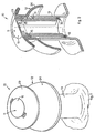
- a closing device 10 for a container 13, able to contain any liquid whatsoever, comprises a first tubular element 11 and a second, cup-shaped element 12 arranged coaxial to said tubular element 11, and able to slide with respect to the latter.
- the elements 11 and 12 are able to define a first configuration as a stopper, as shown in figs. 1 and 2, and a second configuration as a funnel, as shown in figs. 3 and 4.
- the tubular element 11 comprises a first closed end 15 and an opposite open end 16, and is able to be inserted, in one direction or the other, into a mating inlet hole 14 of the container 13.
- a through hole 17 is made, in order to put its tubular cavity into communication with the inside of the container 13 when the device 10 is in its second configuration as a funnel.
- annular packing 18 is arranged in order to guarantee the wet seal of the two elements 11 and 12 in the second configuration as a funnel.
- two sliding seatings 20 are also made longitudinally and diametrically opposite, inside which mating sliding elements 25 slide, made radially on the cup-like element 12.
- clamping recesses 21 and 22 are made radially, respectively towards the first end 15 and towards the second end 16, inside which the sliding elements 25 are positioned with a bayonet-like movement, so as to temporarily and reciprocally clamp the tubular element 11 with the cup-like element 12 in order to define either the first configuration or the second configuration of the closing device 10.
- the cup-like element 12 comprises a first disk 23 and a second disk 24, coaxial to each other and able to slide along the first element 11, instead.
- the first disk is shaped substantially like a mushroom, it comprises the sliding elements 25 in a single piece and functions as a gripper element for the closing device 10 when the latter is in its first configuration as a stopper, whereas it has the function of retaining possible excess liquid when the closing device 10 is in its second configuration as a funnel.
- the second disk 24 is made solid with a part of the first disk 23, and is shaped substantially like a dome, so as to partly surround the top of the container 13 when the closing device 10 is in its configuration as a stopper, and to function as a conveyor for the liquid, whether this is entering or leaving the container 13, when the closing device 10 is in its configuration as a funnel.
- the second disk 24 is shaped like a dome is not essential for the purposes of the present invention.
- the disk 24 can be of any shape, provided that it performs its funnel function.
- the closing device 10 as described heretofore functions as follows.
- the closing device 10 Under normal conditions of use (figs. 1 and 2), the closing device 10 is in its first configuration, with the cup-like element 12 in cooperation with the first end of the tubular element 11, and the latter inserted into the container 13 with its second end 16.
- the first disk 23 completely obstructs the aperture 17, thus preventing the liquid contained in the container 13 from emerging, and the second disk 24 cooperates with the outer surface of the container 13, so as to prevent external agents, such as dust, liquids or otherwise, from inadvertently penetrating inside.
- the closing device 10 is removed from the container 13, gripping the first disk 23.
- the cup-like element 12 is then rotated with respect to the tubular element 11, so that the sliding elements 25 emerge from the clamping recesses 21 and can slide along the sliding seatings 20.
- the cup-like element 12 is made to slide along the sliding seatings 20 until it is taken into cooperation with the second end 16 of the tubular element 11.
- the aperture 17 (figs. 3 and 4) is open and downwards, and the annular packing 18 cooperates with a circular surface of the second disk 24, so as to create a watertight coupling.
- the cup-like element 12 is temporarily clamped in such position with a bayonet-type movement, which allows to displace the sliding elements 25 from the respective guides 20, towards the clamping recesses 22.
- the closing device 10 is positioned in its configuration as a funnel.
- the second disk 24 has its convexity facing towards the outside of the container 13, thus functioning as a conveyor for a liquid, towards the open end 16 of the tubular element 11. In this way the liquid poured is conveyed inside the tubular element 11 and enters into the container 13 through the aperture 17.
- the second disk 24 when the liquid is poured into another container, the second disk 24 also has a drip-catcher function, to prevent such liquid from inadvertently flowing along the outer surface of the container 13.
Landscapes
- Engineering & Computer Science (AREA)
- Mechanical Engineering (AREA)
- Closures For Containers (AREA)
- Filling Of Jars Or Cans And Processes For Cleaning And Sealing Jars (AREA)
- Revetment (AREA)
- Refuse Collection And Transfer (AREA)
- Vacuum Packaging (AREA)
- Devices For Dispensing Beverages (AREA)
- Containers And Packaging Bodies Having A Special Means To Remove Contents (AREA)
- Supply Of Fluid Materials To The Packaging Location (AREA)
- Loading And Unloading Of Fuel Tanks Or Ships (AREA)
Claims (11)
- Schließvorrichtung für einen Behälter (13) für Flüssigkeiten, der mit wenigstens einem Einlassloch (14) ausgebildet ist, um den Auslass oder den Einlass der Flüssigkeiten zu gestatten, wobei ein erstes Element (11) von einer im wesentlichen röhrenartigen Gestalt dazu eingerichtet ist, in das Einlassloch (14) eingefügt zu werden, und wobei ein zweites kappenartiges Element (12) koaxial und außerhalb des ersten Elementes (11) angebracht ist, wobei das erste Element (11) ein erstes geschlossenes Ende (15) und ein zweites offenes Ende (16) aufweist, dadurch gekennzeichnet, dass das zweite kappenartige Element (12) dazu eingerichtet ist, koaxial in Bezug auf das erste Element (11) verschiebbar zu sein, um wahlweise mit dem ersten geschlossenen Ende (15) zusammenzuwirken, um in einer ersten Anordnung einen Stopfen zu bilden, und ebenfalls mit dem zweiten offenen Ende (16) zusammenzuwirken, um in einer zweiten Anordnung einen trichterartigen Durchlass zu bilden, wobei das erste Element (11) wahlweise dazu eingerichtet ist, in der ersten Anordnung mit dem ersten Ende (15) nach außen weisend und in der zweiten Anordnung mit dem ersten Ende (15) nach innen weisend in das Einlassloch (14) eingefügt zu werden.
- Schließvorrichtung nach Anspruch 1, dadurch gekennzeichnet, dass das erste Element (11) an seiner Außenseite Führungsmittel (20, 21, 22, 25) aufweist, die dazu eingerichtet sind, dem zweiten kappenartigen Element (12) zu gestatten, koaxial in Bezug auf das erste Element (11) verschiebbar zu sein.
- Schließvorrichtung nach Anspruch 1, dadurch gekennzeichnet, dass das zweite kappenartige Element (12) ein erstes Teil (23) aufweist, das dazu eingerichtet ist, in der ersten, als Stopfen dienenden Anordnung als ein Griffelement zu wirken und in der zweiten, als trichterartiger Durchlass wirkenden Anordnung einen gegebenenfalls vorhandenen Überschuss an Flüssigkeit zurückzuhalten.
- Schließvorrichtung nach Anspruch 3, dadurch gekennzeichnet, dass das zweite kappenartige Element (12) weiterhin ein zweites Teil (24) aufweist, das koaxial mit dem ersten Teil (23) in Verbindung steht und in der ersten, als Stopfen wirkenden Anordnung dazu eingerichtet ist, wenigstens abschnittsweise den Behälter (13) zu umgeben und als ein Fördermittel für Flüssigkeiten in der zweiten, als trichterartiger Durchlass wirkenden Anordnung zu wirken.
- Schließvorrichtung nach Anspruch 3, dadurch gekennzeichnet, dass das erste Teil (23) eine im wesentlichen ringartige Gestalt hat.
- Schließvorrichtung nach Anspruch 4, dadurch gekennzeichnet, dass das zweite Teil (24) eine im wesentlichen kuppelartige Gestalt hat.
- Schließvorrichtung nach Anspruch 1, dadurch gekennzeichnet, dass das erste Element (11) in der Nähe des ersten geschlossenen Endes (15) eine Öffnung (17) aufweist, die dazu eingerichtet ist, den Flüssigkeiten den Eintritt in den Behälter (13) zu gestatten, wenn das zweite kappenartige Element (12) mit dem zweiten Ende (16) zusammenwirkt.
- Schließvorrichtung nach Anspruch 2, dadurch gekennzeichnet, dass die Führungsmittel wenigstens eine Verschiebeführung (20) aufweisen, die in Längsrichtung an der Außenseite des ersten Elementes (11) ausgebildet ist, und dass zwei Klemmausnehmungen (21, 22) an den Enden und benachbart der Verschiebeführung (20) angeordnet sind.
- Schließvorrichtung nach Anspruch 8, dadurch gekennzeichnet, dass das zweite Element (12) wenigstens ein Verschiebeelement (25) aufweist, das dazu eingerichtet ist, in der Verschiebeführung (20) verschiebbar zu sein und in den Klemmausnehmungen (21, 22) aufgenommen zu werden.
- Schließvorrichtung nach Anspruch 9, dadurch gekennzeichnet, dass das Zusammenwirken des Verschiebeelementes (25) und einer der Klemmausnehmungen (21, 22) das zeitweilige Verklemmen des zweiten Elementes (12) in Bezug auf das erste Element (11) entweder in der ersten Anordnung oder in der zweiten Anordnung bewirkt.
- Schließvorrichtung nach Anspruch 1, dadurch gekennzeichnet, dass das erste Element (11) ringartige Dichtmittel (18) aufweist, die im Bereich des zweiten Endes (16) angeordnet sind, um in der zweiten, als trichterartiger Durchlass wirkenden Anordnung eine wasserdichte Abdichtung sicherzustellen.
Applications Claiming Priority (2)
| Application Number | Priority Date | Filing Date | Title |
|---|---|---|---|
| ITUD20020208 | 2002-10-09 | ||
| IT000208A ITUD20020208A1 (it) | 2002-10-09 | 2002-10-09 | Dispositivo di chiusura, con funzione di imbuto, |
Publications (2)
| Publication Number | Publication Date |
|---|---|
| EP1407979A1 EP1407979A1 (de) | 2004-04-14 |
| EP1407979B1 true EP1407979B1 (de) | 2007-09-05 |
Family
ID=32012194
Family Applications (1)
| Application Number | Title | Priority Date | Filing Date |
|---|---|---|---|
| EP03103672A Expired - Lifetime EP1407979B1 (de) | 2002-10-09 | 2003-10-03 | Schliessvorrichtung, mit Trichter Funktion, für Flüssigkeitsbehälter |
Country Status (5)
| Country | Link |
|---|---|
| EP (1) | EP1407979B1 (de) |
| AT (1) | ATE372275T1 (de) |
| DE (1) | DE60316085T2 (de) |
| ES (1) | ES2292903T3 (de) |
| IT (1) | ITUD20020208A1 (de) |
Families Citing this family (1)
| Publication number | Priority date | Publication date | Assignee | Title |
|---|---|---|---|---|
| EP4185540A1 (de) * | 2020-07-24 | 2023-05-31 | Hipp & Co | Behältervorrichtung mit adaptervorrichtung, adaptervorrichtung, deckeleinrichtung, system aus deckeleinrichtung und adaptervorrichtung und verfahren |
Family Cites Families (4)
| Publication number | Priority date | Publication date | Assignee | Title |
|---|---|---|---|---|
| US2780397A (en) * | 1954-10-28 | 1957-02-05 | Edward W Larrabee | Disposable liquid dispensing device |
| SE460187B (sv) * | 1987-06-16 | 1989-09-18 | Soederhamn Innovation Ab | Tratt foer paafyllning av vaetska i behaallare |
| DE4427824A1 (de) * | 1994-08-05 | 1995-02-23 | Mutlu Kuzey | Trichter-Einfüllspitzenkombination mit Gewinde |
| US6223792B1 (en) * | 1999-05-28 | 2001-05-01 | Ray N. Slagle | Funnel cap device for a fluid container |
-
2002
- 2002-10-09 IT IT000208A patent/ITUD20020208A1/it unknown
-
2003
- 2003-10-03 AT AT03103672T patent/ATE372275T1/de not_active IP Right Cessation
- 2003-10-03 EP EP03103672A patent/EP1407979B1/de not_active Expired - Lifetime
- 2003-10-03 DE DE60316085T patent/DE60316085T2/de not_active Expired - Fee Related
- 2003-10-03 ES ES03103672T patent/ES2292903T3/es not_active Expired - Lifetime
Also Published As
| Publication number | Publication date |
|---|---|
| DE60316085T2 (de) | 2008-05-29 |
| ES2292903T3 (es) | 2008-03-16 |
| ITUD20020208A1 (it) | 2004-04-10 |
| ATE372275T1 (de) | 2007-09-15 |
| DE60316085D1 (de) | 2007-10-18 |
| EP1407979A1 (de) | 2004-04-14 |
Similar Documents
| Publication | Publication Date | Title |
|---|---|---|
| JP4316809B2 (ja) | コンテナ用密閉バルブ | |
| EP1047625B1 (de) | Hahn mit eingebautem lüftungskanal | |
| US5042698A (en) | Easy pour spout | |
| EP3157834B1 (de) | Verschluss mit speicherkammer | |
| US20180215605A1 (en) | Closed System Valve Assembly With Expanded Flow Path | |
| KR20100072320A (ko) | 용기 마개용 시트재 천공구 | |
| US9254944B1 (en) | Assembly and method for pouring liquid from a container | |
| KR100416961B1 (ko) | 개폐형 빨대 | |
| EP1347936B1 (de) | Anzapfstange | |
| EP3094571B1 (de) | Abgabeverschlussanordnung mit vorabentlüftung | |
| EP1028903B1 (de) | Ausgiessvorrichtung | |
| PL191042B1 (pl) | Wpuszczany kurek czerpalny | |
| US3828981A (en) | Safety dispensing device | |
| WO1995013220A1 (en) | Pouring spout | |
| US6568566B2 (en) | Container closure with horizontal and vertical seals | |
| EP1407979B1 (de) | Schliessvorrichtung, mit Trichter Funktion, für Flüssigkeitsbehälter | |
| EP1693310A1 (de) | Dosierverschluss | |
| US20080257884A1 (en) | Cap for a Receptacle | |
| WO1996001216A3 (en) | Pour spout assembly for bottles | |
| EP0298247A1 (de) | Verschlussvorrichtung für Flaschen | |
| WO2003026999A1 (en) | Container closure with horizontal and vertical seals | |
| WO2021142228A1 (en) | Selective flow cohesive streaming caps | |
| JPH10167309A (ja) | 複合キャップ | |
| JP2014129100A (ja) | 詰め替え容器 | |
| US20060278656A1 (en) | Spout handle and nozzle assembly |
Legal Events
| Date | Code | Title | Description |
|---|---|---|---|
| PUAI | Public reference made under article 153(3) epc to a published international application that has entered the european phase |
Free format text: ORIGINAL CODE: 0009012 |
|
| AK | Designated contracting states |
Kind code of ref document: A1 Designated state(s): AT BE BG CH CY CZ DE DK EE ES FI FR GB GR HU IE IT LI LU MC NL PT RO SE SI SK TR |
|
| AX | Request for extension of the european patent |
Extension state: AL LT LV MK |
|
| 17P | Request for examination filed |
Effective date: 20040930 |
|
| AKX | Designation fees paid |
Designated state(s): AT BE BG CH CY CZ DE DK EE ES FI FR GB GR HU IE IT LI LU MC NL PT RO SE SI SK TR |
|
| RAP1 | Party data changed (applicant data changed or rights of an application transferred) |
Owner name: UNITEKNO SPA |
|
| GRAP | Despatch of communication of intention to grant a patent |
Free format text: ORIGINAL CODE: EPIDOSNIGR1 |
|
| GRAS | Grant fee paid |
Free format text: ORIGINAL CODE: EPIDOSNIGR3 |
|
| GRAA | (expected) grant |
Free format text: ORIGINAL CODE: 0009210 |
|
| AK | Designated contracting states |
Kind code of ref document: B1 Designated state(s): AT BE BG CH CY CZ DE DK EE ES FI FR GB GR HU IE IT LI LU MC NL PT RO SE SI SK TR |
|
| REG | Reference to a national code |
Ref country code: GB Ref legal event code: FG4D |
|
| REG | Reference to a national code |
Ref country code: CH Ref legal event code: EP |
|
| REF | Corresponds to: |
Ref document number: 60316085 Country of ref document: DE Date of ref document: 20071018 Kind code of ref document: P |
|
| REG | Reference to a national code |
Ref country code: IE Ref legal event code: FG4D |
|
| PG25 | Lapsed in a contracting state [announced via postgrant information from national office to epo] |
Ref country code: FI Free format text: LAPSE BECAUSE OF FAILURE TO SUBMIT A TRANSLATION OF THE DESCRIPTION OR TO PAY THE FEE WITHIN THE PRESCRIBED TIME-LIMIT Effective date: 20070905 |
|
| REG | Reference to a national code |
Ref country code: CH Ref legal event code: NV Representative=s name: R. A. EGLI & CO. PATENTANWAELTE |
|
| NLV1 | Nl: lapsed or annulled due to failure to fulfill the requirements of art. 29p and 29m of the patents act | ||
| REG | Reference to a national code |
Ref country code: ES Ref legal event code: FG2A Ref document number: 2292903 Country of ref document: ES Kind code of ref document: T3 |
|
| PG25 | Lapsed in a contracting state [announced via postgrant information from national office to epo] |
Ref country code: BE Free format text: LAPSE BECAUSE OF FAILURE TO SUBMIT A TRANSLATION OF THE DESCRIPTION OR TO PAY THE FEE WITHIN THE PRESCRIBED TIME-LIMIT Effective date: 20070905 |
|
| ET | Fr: translation filed | ||
| PG25 | Lapsed in a contracting state [announced via postgrant information from national office to epo] |
Ref country code: GR Free format text: LAPSE BECAUSE OF FAILURE TO SUBMIT A TRANSLATION OF THE DESCRIPTION OR TO PAY THE FEE WITHIN THE PRESCRIBED TIME-LIMIT Effective date: 20071206 Ref country code: NL Free format text: LAPSE BECAUSE OF FAILURE TO SUBMIT A TRANSLATION OF THE DESCRIPTION OR TO PAY THE FEE WITHIN THE PRESCRIBED TIME-LIMIT Effective date: 20070905 |
|
| PG25 | Lapsed in a contracting state [announced via postgrant information from national office to epo] |
Ref country code: MC Free format text: LAPSE BECAUSE OF NON-PAYMENT OF DUE FEES Effective date: 20071031 Ref country code: CZ Free format text: LAPSE BECAUSE OF FAILURE TO SUBMIT A TRANSLATION OF THE DESCRIPTION OR TO PAY THE FEE WITHIN THE PRESCRIBED TIME-LIMIT Effective date: 20070905 Ref country code: PT Free format text: LAPSE BECAUSE OF FAILURE TO SUBMIT A TRANSLATION OF THE DESCRIPTION OR TO PAY THE FEE WITHIN THE PRESCRIBED TIME-LIMIT Effective date: 20080206 Ref country code: SK Free format text: LAPSE BECAUSE OF FAILURE TO SUBMIT A TRANSLATION OF THE DESCRIPTION OR TO PAY THE FEE WITHIN THE PRESCRIBED TIME-LIMIT Effective date: 20070905 |
|
| PG25 | Lapsed in a contracting state [announced via postgrant information from national office to epo] |
Ref country code: RO Free format text: LAPSE BECAUSE OF FAILURE TO SUBMIT A TRANSLATION OF THE DESCRIPTION OR TO PAY THE FEE WITHIN THE PRESCRIBED TIME-LIMIT Effective date: 20070905 Ref country code: SE Free format text: LAPSE BECAUSE OF FAILURE TO SUBMIT A TRANSLATION OF THE DESCRIPTION OR TO PAY THE FEE WITHIN THE PRESCRIBED TIME-LIMIT Effective date: 20071205 |
|
| PLBE | No opposition filed within time limit |
Free format text: ORIGINAL CODE: 0009261 |
|
| STAA | Information on the status of an ep patent application or granted ep patent |
Free format text: STATUS: NO OPPOSITION FILED WITHIN TIME LIMIT |
|
| PG25 | Lapsed in a contracting state [announced via postgrant information from national office to epo] |
Ref country code: DK Free format text: LAPSE BECAUSE OF FAILURE TO SUBMIT A TRANSLATION OF THE DESCRIPTION OR TO PAY THE FEE WITHIN THE PRESCRIBED TIME-LIMIT Effective date: 20070905 |
|
| 26N | No opposition filed |
Effective date: 20080606 |
|
| GBPC | Gb: european patent ceased through non-payment of renewal fee |
Effective date: 20071205 |
|
| PG25 | Lapsed in a contracting state [announced via postgrant information from national office to epo] |
Ref country code: IE Free format text: LAPSE BECAUSE OF NON-PAYMENT OF DUE FEES Effective date: 20071003 |
|
| PG25 | Lapsed in a contracting state [announced via postgrant information from national office to epo] |
Ref country code: GB Free format text: LAPSE BECAUSE OF NON-PAYMENT OF DUE FEES Effective date: 20071205 |
|
| PG25 | Lapsed in a contracting state [announced via postgrant information from national office to epo] |
Ref country code: EE Free format text: LAPSE BECAUSE OF FAILURE TO SUBMIT A TRANSLATION OF THE DESCRIPTION OR TO PAY THE FEE WITHIN THE PRESCRIBED TIME-LIMIT Effective date: 20070905 |
|
| PGFP | Annual fee paid to national office [announced via postgrant information from national office to epo] |
Ref country code: CH Payment date: 20081015 Year of fee payment: 6 Ref country code: DE Payment date: 20081022 Year of fee payment: 6 |
|
| PGFP | Annual fee paid to national office [announced via postgrant information from national office to epo] |
Ref country code: AT Payment date: 20081015 Year of fee payment: 6 Ref country code: ES Payment date: 20081027 Year of fee payment: 6 |
|
| PGFP | Annual fee paid to national office [announced via postgrant information from national office to epo] |
Ref country code: IT Payment date: 20081023 Year of fee payment: 6 |
|
| PGFP | Annual fee paid to national office [announced via postgrant information from national office to epo] |
Ref country code: FR Payment date: 20081014 Year of fee payment: 6 |
|
| PG25 | Lapsed in a contracting state [announced via postgrant information from national office to epo] |
Ref country code: SI Free format text: LAPSE BECAUSE OF FAILURE TO SUBMIT A TRANSLATION OF THE DESCRIPTION OR TO PAY THE FEE WITHIN THE PRESCRIBED TIME-LIMIT Effective date: 20070905 |
|
| PG25 | Lapsed in a contracting state [announced via postgrant information from national office to epo] |
Ref country code: CY Free format text: LAPSE BECAUSE OF FAILURE TO SUBMIT A TRANSLATION OF THE DESCRIPTION OR TO PAY THE FEE WITHIN THE PRESCRIBED TIME-LIMIT Effective date: 20070905 |
|
| PG25 | Lapsed in a contracting state [announced via postgrant information from national office to epo] |
Ref country code: LU Free format text: LAPSE BECAUSE OF NON-PAYMENT OF DUE FEES Effective date: 20071003 Ref country code: BG Free format text: LAPSE BECAUSE OF FAILURE TO SUBMIT A TRANSLATION OF THE DESCRIPTION OR TO PAY THE FEE WITHIN THE PRESCRIBED TIME-LIMIT Effective date: 20071205 |
|
| PG25 | Lapsed in a contracting state [announced via postgrant information from national office to epo] |
Ref country code: HU Free format text: LAPSE BECAUSE OF FAILURE TO SUBMIT A TRANSLATION OF THE DESCRIPTION OR TO PAY THE FEE WITHIN THE PRESCRIBED TIME-LIMIT Effective date: 20080306 Ref country code: TR Free format text: LAPSE BECAUSE OF FAILURE TO SUBMIT A TRANSLATION OF THE DESCRIPTION OR TO PAY THE FEE WITHIN THE PRESCRIBED TIME-LIMIT Effective date: 20070905 |
|
| REG | Reference to a national code |
Ref country code: CH Ref legal event code: PL |
|
| REG | Reference to a national code |
Ref country code: FR Ref legal event code: ST Effective date: 20100630 |
|
| PG25 | Lapsed in a contracting state [announced via postgrant information from national office to epo] |
Ref country code: FR Free format text: LAPSE BECAUSE OF NON-PAYMENT OF DUE FEES Effective date: 20091102 Ref country code: DE Free format text: LAPSE BECAUSE OF NON-PAYMENT OF DUE FEES Effective date: 20100501 |
|
| PG25 | Lapsed in a contracting state [announced via postgrant information from national office to epo] |
Ref country code: AT Free format text: LAPSE BECAUSE OF NON-PAYMENT OF DUE FEES Effective date: 20091003 |
|
| PG25 | Lapsed in a contracting state [announced via postgrant information from national office to epo] |
Ref country code: LI Free format text: LAPSE BECAUSE OF NON-PAYMENT OF DUE FEES Effective date: 20091031 Ref country code: CH Free format text: LAPSE BECAUSE OF NON-PAYMENT OF DUE FEES Effective date: 20091031 |
|
| REG | Reference to a national code |
Ref country code: ES Ref legal event code: FD2A Effective date: 20110309 |
|
| PG25 | Lapsed in a contracting state [announced via postgrant information from national office to epo] |
Ref country code: IT Free format text: LAPSE BECAUSE OF NON-PAYMENT OF DUE FEES Effective date: 20091003 |
|
| PG25 | Lapsed in a contracting state [announced via postgrant information from national office to epo] |
Ref country code: ES Free format text: LAPSE BECAUSE OF NON-PAYMENT OF DUE FEES Effective date: 20110308 |
|
| PG25 | Lapsed in a contracting state [announced via postgrant information from national office to epo] |
Ref country code: ES Free format text: LAPSE BECAUSE OF NON-PAYMENT OF DUE FEES Effective date: 20091004 |